stop start Lancia Musa 2011 Owner handbook (in English)
[x] Cancel search | Manufacturer: LANCIA, Model Year: 2011, Model line: Musa, Model: Lancia Musa 2011Pages: 218, PDF Size: 3.91 MB
Page 13 of 218
12
SAFETY
STARTING
AND DRIVING
WARNING
LIGHTS AND
MESSAGES
IN AN
EMERGENCY
MAINTENANCE
AND CARE
TECHNICAL
SPECIFICA-
TIONS
INDEX
DASHBOARD
AND
CONTROLS
Warning light
Ycoming on
when driving
❒If the warning light Yturns on,
this means that the system is run-
ning a self-test (for example for a
voltage drop).
❒If the fault persists, contact a Lan-
cia Dealership.
OPERATION
Each time the car is started turning
the ignition key to MAR, the Lancia
CODE system control unit sends a
recognition code to the engine control
unit to activate the functions. The
code is sent only if the Lancia CODE
system control unit has recognised the
code transmitted from the key. Each
time the ignition key is turned to
STOP, the Lancia CODE system de-
activates the functions of the engine
electronic control unit.
If the code has not been recognised
correctly, the warning light
Yturns
on on the display.The electronic components
inside the key may be dam-
aged if the key is submitted
to sharp knocks.
In this case, turn the key to STOP
and then back to MAR; try with the
other keys provided if the problem
persists. Contact a Lancia Dealership
if you still cannot start the engine.
IMPORTANT Each key has its own
code which must be stored by the sys-
tem electronic control unit. Contact a
Fiat Dealership to have new keys (up
to eight) stored.
Page 21 of 218
20
SAFETY
STARTING
AND DRIVING
WARNING
LIGHTS AND
MESSAGES
IN AN
EMERGENCY
MAINTENANCE
AND CARE
TECHNICAL
SPECIFICA-
TIONS
INDEX
DASHBOARD
AND
CONTROLS
IGNITION SWITCH
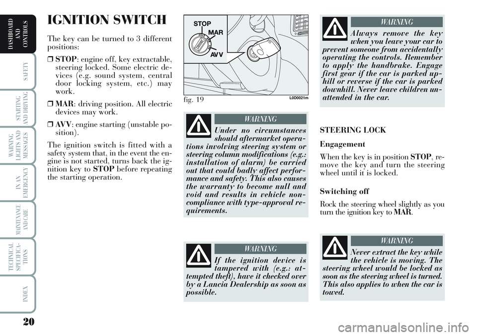
The key can be turned to 3 different
positions:
❒STOP: engine off, key extractable,
steering locked. Some electric de-
vices (e.g. sound system, central
door locking system, etc.) may
work.
❒MAR: driving position. All electric
devices may work.
❒AV V: engine starting (unstable po-
sition).
The ignition switch is fitted with a
safety system that, in the event the en-
gine is not started, turns back the ig-
nition key to STOPbefore repeating
the starting operation.
Under no circumstances
should aftermarket opera-
tions involving steering system or
steering column modifications (e.g.:
installation of alarm) be carried
out that could badly affect perfor-
mance and safety. This also causes
the warranty to become null and
void and results in vehicle non-
compliance with type-approval re-
quirements.
WARNING
fig. 19L0D0021m
If the ignition device is
tampered with (e.g.: at-
tempted theft), have it checked over
by a Lancia Dealership as soon as
possible.
WARNING
Always remove the key
when you leave your car to
prevent someone from accidentally
operating the controls. Remember
to apply the handbrake. Engage
first gear if the car is parked up-
hill or reverse if the car is parked
downhill. Never leave children un-
attended in the car.
WARNING
STEERING LOCK
Engagement
When the key is in position STOP, re-
move the key and turn the steering
wheel until it is locked.
Switching off
Rock the steering wheel slightly as you
turn the ignition key to MAR.
Never extract the key while
the vehicle is moving. The
steering wheel would be locked as
soon as the steering wheel is turned.
This also applies to when the car is
towed.
WARNING
Page 23 of 218
22
SAFETY
STARTING
AND DRIVING
WARNING
LIGHTS AND
MESSAGES
IN AN
EMERGENCY
MAINTENANCE
AND CARE
TECHNICAL
SPECIFICA-
TIONS
INDEX
DASHBOARD
AND
CONTROLS
MULTIFUNCTIONAL
DISPLAY
(on two-line modal
panel)
The car can be equipped with the mul-
tifunction display for showing useful in-
formation necessary when driving ac-
cording to settings. ENGINE
COOLANT TEMPERATURE
GAUGE fig. 23
Warning light Aindicates overheating
of the engine coolant. In this case, stop
the engine and contact a Lancia Deal-
ership. This shows the temperature of
the engine coolant fluid and starts
working when the fluid temperature ex-
ceeds approx. 50°C. In normal condi-
tions, the needle may point to different
positions according to use and the en-
gine cooling system management.
IMPORTANT The needle will point to
the lowest value of the scale (low tem-
perature) and warning light Awill
light up to indicate a fault in the sys-
tem. Go to a Lancia Dealership to
have the system checked.
If the needle reaches the red
area, stop the engine imme-
diately and contact a Lan-
cia Dealership.
fig. 24L0D0497m
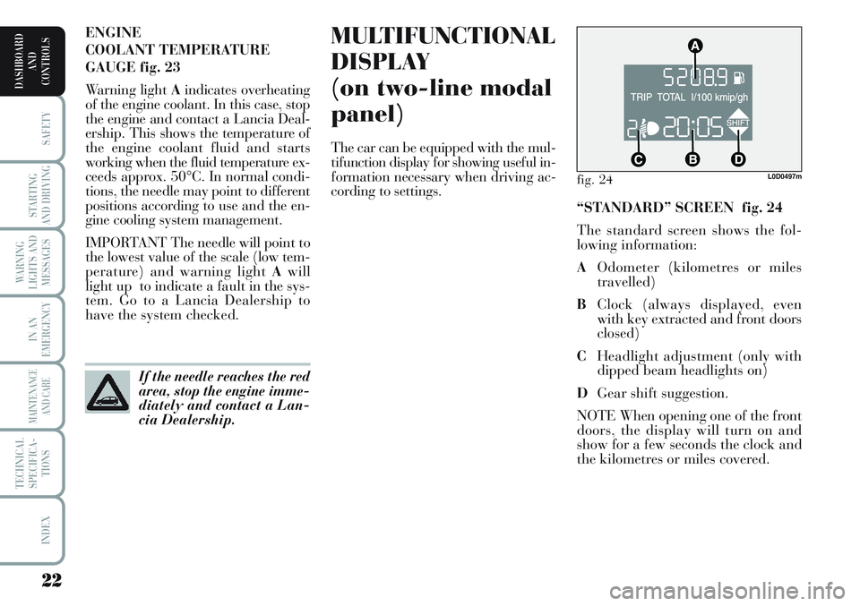
“STANDARD” SCREEN fig. 24
The standard screen shows the fol-
lowing information:
AOdometer (kilometres or miles
travelled)
BClock (always displayed, even
with key extracted and front doors
closed)
CHeadlight adjustment (only with
dipped beam headlights on)
DGear shift suggestion.
NOTE When opening one of the front
doors, the display will turn on and
show for a few seconds the clock and
the kilometres or miles covered.
Page 28 of 218
27
SAFETY
STARTING
AND DRIVING
WARNING
LIGHTS AND
MESSAGES
IN AN
EMERGENCY
MAINTENANCE
AND CARE
TECHNICAL
SPECIFICA-
TIONS
INDEX
DASHBOARD
AND
CONTROLS
Day
Ye a rMonth Example:
CONSUMPTION QUIT MENU SPEED LIMIT SET CLOCK LIGHT SENSOR TRIP B
CLOCK MODE
SET DATE
KEY
UNIT DIST.
BUTTON VOLUME
BUZZER VOLUME SERVICE
LANGUAGETEMP. UNIT
Example:
– +
+– – –
+ +
–
–
+
+++
–––
+ +
–
MODE
button
pressed
briefly
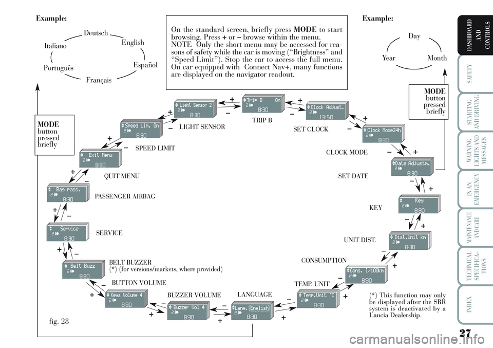
On the standard screen, briefly press MODEto start
browsing. Press +or–browse within the menu.
NOTE Only the short menu may be accessed for rea-
sons of safety while the car is moving (“Brightness” and
“Speed Limit”). Stop the car to access the full menu.
On car equipped with Connect Nav+, many functions
are displayed on the navigator readout.
–
+ +
–
MODE
button
pressed
briefly
Deutsch
English
Español
Italiano
Português
Français
(*) This function may only
be displayed after the SBR
system is deactivated by a
Lancia Dealership.
fig. 28
+
– +
–+
–
+
–
+ –
BELT BUZZER
(*) (for versions/markets, where provided) PASSENGER AIRBAG
Page 50 of 218
49
SAFETY
STARTING
AND DRIVING
WARNING
LIGHTS AND
MESSAGES
IN AN
EMERGENCY
MAINTENANCE
AND CARE
TECHNICAL
SPECIFICA-
TIONS
INDEX
DASHBOARD
AND
CONTROLS
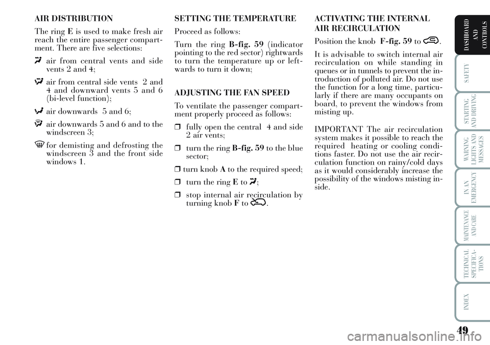
AIR DISTRIBUTION
The ring Eis used to make fresh air
reach the entire passenger compart-
ment. There are five selections:
«air from central vents and side
vents 2 and 4;
Δair from central side vents 2 and
4 and downward vents 5 and 6
(bi-level function);
≈air downwards 5 and 6;
ƒair downwards 5 and 6 and to the
windscreen 3;
-for demisting and defrosting the
windscreen 3 and the front side
windows 1.ACTIVATING THE INTERNAL
AIR RECIRCULATION
Position the knob F-fig. 59to
….
It is advisable to switch internal air
recirculation on while standing in
queues or in tunnels to prevent the in-
troduction of polluted air. Do not use
the function for a long time, particu-
larly if there are many occupants on
board, to prevent the windows from
misting up.
IMPORTANT The air recirculation
system makes it possible to reach the
required heating or cooling condi-
tions faster. Do not use the air recir-
culation function on rainy/cold days
as it would considerably increase the
possibility of the windows misting in-
side. SETTING THE TEMPERATURE
Proceed as follows:
Turn the ring B-fig. 59(indicator
pointing to the red sector) rightwards
to turn the temperature up or left-
wards to turn it down;
ADJUSTING THE FAN SPEED
To ventilate the passenger compart-
ment properly proceed as follows:
❒fully open the central 4 and side
2 air vents;
❒turn the ring B-fig. 59to the blue
sector;
❒turn knob Ato the required speed;
❒turn the ring Eto«;
❒stop internal air recirculation by
turning knob Fto
Ú.
Page 51 of 218
50
SAFETY
STARTING
AND DRIVING
WARNING
LIGHTS AND
MESSAGES
IN AN
EMERGENCY
MAINTENANCE
AND CARE
TECHNICAL
SPECIFICA-
TIONS
INDEX
DASHBOARD
AND
CONTROLS
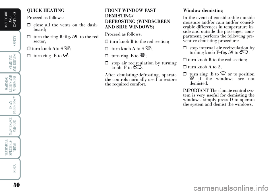
Window demisting
In the event of considerable outside
moisture and/or rain and/or consid-
erable differences in temperature in-
side and outside the passenger com-
partment, perform the following pre-
ventive demisting procedure:
❒stop internal air recirculation by
turning knob F-fig. 59to
Ú.
❒turn knob Bto the red section;
❒turn knob Ato 2;
❒turn ring Eto
-or to positionƒif the windows are not
demisted.
IMPORTANT The climate control sys-
tem is very useful for demisting the
windows: simply press Dto operate
the system and demist the windows. FRONT WINDOW FAST
DEMISTING/
DEFROSTING (WINDSCREEN
AND SIDE WINDOWS)
Proceed as follows:
❒turn knob Bto the red section;
❒turn knob Ato 4
-;
❒turn ring Eto
-;
❒stop air recirculation by turning
knobFto
Ú.
After demisting/defrosting, operate
the controls normally used to restore
the required comfort. QUICK HEATING
Proceed as follows:
❒close all the vents on the dash-
board;
❒turn the ring B-fig. 59to the red
sector;
❒turn knob Ato 4
-;
❒turn ring Eto
≈.
Page 52 of 218
51
SAFETY
STARTING
AND DRIVING
WARNING
LIGHTS AND
MESSAGES
IN AN
EMERGENCY
MAINTENANCE
AND CARE
TECHNICAL
SPECIFICA-
TIONS
INDEX
DASHBOARD
AND
CONTROLS
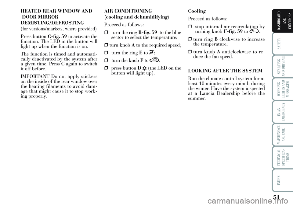
HEATED REAR WINDOW AND
DOOR MIRROR
DEMISTING/DEFROSTING
(for versions/markets, where provided)
Press button C-fig. 59to activate the
function. The LED in the button will
light up when the function is on.
The function is timed and automati-
cally deactivated by the system after
a given time. Press Cagain to switch
it off before.
IMPORTANT Do not apply stickers
on the inside of the rear window over
the heating filaments to avoid dam-
age that might cause it to stop work-
ing properly.Cooling
Proceed as follows:
❒stop internal air recirculation by
turning knob F-fig. 59to
Ú.
❒turn ring Bclockwise to increase
the temperature;
❒turn knob Aanticlockwise to re-
duce the fan speed.
LOOKING AFTER THE SYSTEM
Run the climate control system for at
least 10 minutes every month during
the winter. Have the system inspected
at a Lancia Dealership before the
summer. AIR CONDITIONING
(cooling and dehumidifying)
Proceed as follows:
❒turn the ring B-fig. 59to the blue
sector to select the temperature;
❒turn knob Ato the required speed;
❒turn the ring Eto
«;
❒turn the knob Fto
….
❒press button D
√(the LED on the
button will light up).
Page 61 of 218
60
SAFETY
STARTING
AND DRIVING
WARNING
LIGHTS AND
MESSAGES
IN AN
EMERGENCY
MAINTENANCE
AND CARE
TECHNICAL
SPECIFICA-
TIONS
INDEX
DASHBOARD
AND
CONTROLS
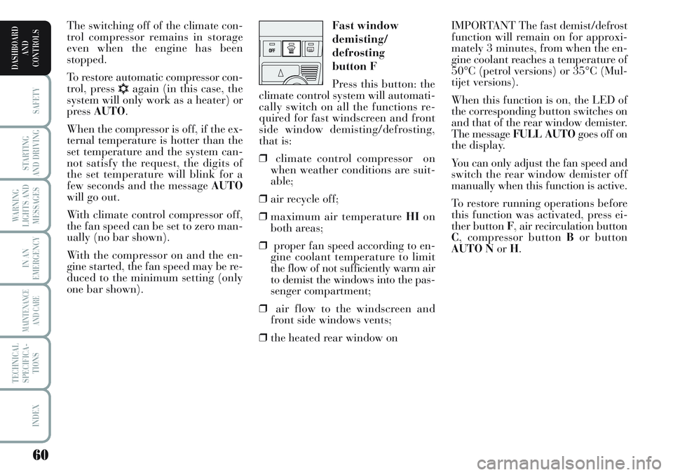
IMPORTANT The fast demist/defrost
function will remain on for approxi-
mately 3 minutes, from when the en-
gine coolant reaches a temperature of
50°C (petrol versions) or 35°C (Mul-
tijet versions).
When this function is on, the LED of
the corresponding button switches on
and that of the rear window demister.
The message FULL AUTOgoes off on
the display.
You can only adjust the fan speed and
switch the rear window demister off
manually when this function is active.
To restore running operations before
this function was activated, press ei-
ther button F, air recirculation button
C, compressor button Bor button
AUTO NorH. Fast window
demisting/
defrosting
button F
Press this button: the
climate control system will automati-
cally switch on all the functions re-
quired for fast windscreen and front
side window demisting/defrosting,
that is:
❒climate control compressor on
when weather conditions are suit-
able;
❒air recycle off;
❒maximum air temperature HIon
both areas;
❒proper fan speed according to en-
gine coolant temperature to limit
the flow of not sufficiently warm air
to demist the windows into the pas-
senger compartment;
❒air flow to the windscreen and
front side windows vents;
❒the heated rear window on The switching off of the climate con-
trol compressor remains in storage
even when the engine has been
stopped.
To restore automatic compressor con-
trol, press
√again (in this case, the
system will only work as a heater) or
press AUTO.
When the compressor is off, if the ex-
ternal temperature is hotter than the
set temperature and the system can-
not satisfy the request, the digits of
the set temperature will blink for a
few seconds and the message AUTO
will go out.
With climate control compressor off,
the fan speed can be set to zero man-
ually (no bar shown).
With the compressor on and the en-
gine started, the fan speed may be re-
duced to the minimum setting (only
one bar shown).
Page 62 of 218
61
SAFETY
STARTING
AND DRIVING
WARNING
LIGHTS AND
MESSAGES
IN AN
EMERGENCY
MAINTENANCE
AND CARE
TECHNICAL
SPECIFICA-
TIONS
INDEX
DASHBOARD
AND
CONTROLS
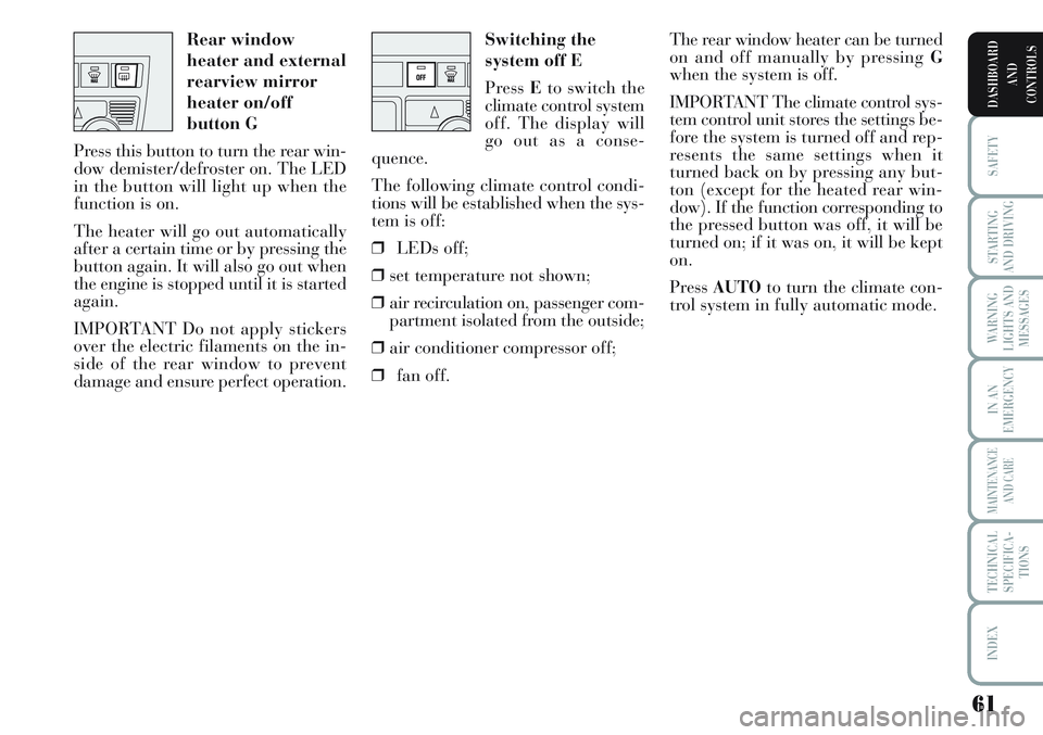
Switching the
system off E
Press Eto switch the
climate control system
off. The display will
go out as a conse-
quence.
The following climate control condi-
tions will be established when the sys-
tem is off:
❒LEDs off;
❒set temperature not shown;
❒air recirculation on, passenger com-
partment isolated from the outside;
❒air conditioner compressor off;
❒fan off.The rear window heater can be turned
on and off manually by pressing G
when the system is off.
IMPORTANT The climate control sys-
tem control unit stores the settings be-
fore the system is turned off and rep-
resents the same settings when it
turned back on by pressing any but-
ton (except for the heated rear win-
dow). If the function corresponding to
the pressed button was off, it will be
turned on; if it was on, it will be kept
on.
Press AUTOto turn the climate con-
trol system in fully automatic mode. Rear window
heater and external
rearview mirror
heater on/off
button G
Press this button to turn the rear win-
dow demister/defroster on. The LED
in the button will light up when the
function is on.
The heater will go out automatically
after a certain time or by pressing the
button again. It will also go out when
the engine is stopped until it is started
again.
IMPORTANT Do not apply stickers
over the electric filaments on the in-
side of the rear window to prevent
damage and ensure perfect operation.
Page 63 of 218
62
SAFETY
STARTING
AND DRIVING
WARNING
LIGHTS AND
MESSAGES
IN AN
EMERGENCY
MAINTENANCE
AND CARE
TECHNICAL
SPECIFICA-
TIONS
INDEX
DASHBOARD
AND
CONTROLS
PARKING LIGHTS fig. 65
With the key at STOPor extracted,
turn the ring to position
6. Warning
light
3on the instrument panel will
go on with the side/taillights and the
number plate lights. Move the stalk
upwards
ato turn on the right side
lights only; move it downwards bto
turn on the left side lights only. In ei-
ther case, warning light
3will not
light up on the instrument cluster. FLASHING THE HEADLIGHTS
Pull the stalk towards the steering
wheel (unstable position) regardless
of the position of the ring. The warn-
ing light
1on the instrument cluster
will come on at the same time.
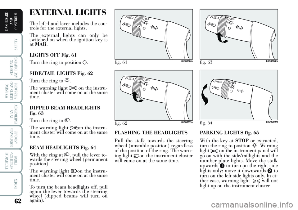
fig. 61L0D0066m
fig. 64L0D0069m
fig. 63L0D0068m
fig. 62L0D0067m
EXTERNAL LIGHTS
The left-hand lever includes the con-
trols for the external lights.
The external lights can only be
switched on when the ignition key is
atMAR.
LIGHTS OFF Fig. 61
Turn the ring to position
å.
SIDE/TAIL LIGHTS Fig. 62
Turn the ring to
6.
The warning light
3on the instru-
ment cluster will come on at the same
time.
DIPPED BEAM HEADLIGHTS
fig. 63
Turn the ring to
2.
The warning light
3on the instru-
ment cluster will come on at the same
time.
BEAM HEADLIGHTS Fig. 64
With the ring at
2, pull the lever to-
wards the steering wheel (permanent
position).
The warning light
1on the instru-
ment cluster will come on at the same
time.
To turn the beam headlights off, pull
again the lever towards the steering
wheel (dipped beams will turn on
again).