steering Lancia Musa 2012 Owner handbook (in English)
[x] Cancel search | Manufacturer: LANCIA, Model Year: 2012, Model line: Musa, Model: Lancia Musa 2012Pages: 218, PDF Size: 3.91 MB
Page 91 of 218
90
SAFETY
STARTING
AND DRIVING
WARNING
LIGHTS AND
MESSAGES
IN AN
EMERGENCY
MAINTENANCE
AND CARE
TECHNICAL
SPECIFICA-
TIONS
INDEX
DASHBOARD
AND
CONTROLS
The car can be driven using the me-
chanical steering in case of failure to
the electric power steering system.
Take the car to a Lancia Dealership
as soon as possible.
IMPORTANT The steering may be-
fore stiffer when parking requiring a
lot of steering. This is normal and
caused by the electric control motor
overheating system. No repairs are
needed. The power steering system
will start working properly again the
next time the car is used. PARKING SENSORS
(for versions/markets, where provided)
Parking sensors are located in the rear
bumper and their function is to in-
form the driver, through an intermit-
tent buzzer, about the presence of ob-
stacles behind the car.
ACTIVATION
The sensors are automatically acti-
vated when the reverse gear is en-
gaged. As the distance from the ob-
stacle behind the car decreases, the
acoustic alarm becomes more fre-
quent.
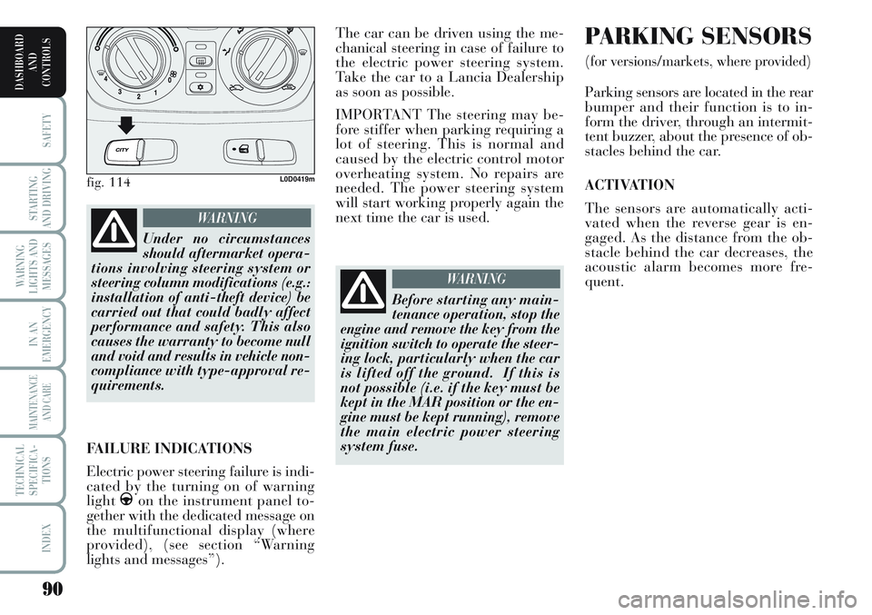
fig. 114L0D0419m
Under no circumstances
should aftermarket opera-
tions involving steering system or
steering column modifications (e.g.:
installation of anti-theft device) be
carried out that could badly affect
performance and safety. This also
causes the warranty to become null
and void and results in vehicle non-
compliance with type-approval re-
quirements.
WARNING
FAILURE INDICATIONS
Electric power steering failure is indi-
cated by the turning on of warning
light
gon the instrument panel to-
gether with the dedicated message on
the multifunctional display (where
provided), (see section “Warning
lights and messages”).
Before starting any main-
tenance operation, stop the
engine and remove the key from the
ignition switch to operate the steer-
ing lock, particularly when the car
is lifted off the ground. If this is
not possible (i.e. if the key must be
kept in the MAR position or the en-
gine must be kept running), remove
the main electric power steering
system fuse.
WARNING
Page 109 of 218

108
STARTING
AND DRIVING
WARNING
LIGHTS AND
MESSAGES
IN AN
EMERGENCY
MAINTENANCE
AND CARE
TECHNICAL
SPECIFICA-
TIONS
INDEX
DASHBOARD
AND
CONTROLS
SAFETY
FRONT AIRBAGS
The car is provided with front airbags
for the driver and passenger and win-
dow bags (head protection system). It
may be provided with optional front
side bags.
The front driver / passenger air bags
have been designed to protect the oc-
cupants in the event of head-on
crashes of medium-high severity, by
placing the cushion between the oc-
cupant and the steering wheel or
dashboard.
Front air bags are designed to protect
car’s occupants in front crashes and
therefore non-activation in other types
of collisions (side collisions, rear
shunts, roll-overs, etc.) is not a system
malfunction.
An electronic control unit will make
the bag inflate in the event of a frontal
crash.
The bag will inflate instantaneously
placing itself between the front occu-
pant’s body and the structures which
could cause injury. It will deflate im-
mediately afterwards.
Driver and passenger front airbags are
not a replacement of but complemen-
tary to the belts, which you are rec-
ommended to always wear, as speci-
fied by law in Europe and most non-
European countries.In the event of a collision, a person
not wearing a seat belt may be thrown
forward and con into contact with the
bag before it has fully opened. The
protection offered by the cushion is
reduced in such a case.
Front air bag may not be activated in
the following situations:
❒in collisions against highly de-
formable objects not affecting the
car front surface (e.g. bumper col-
lision against guard rail, etc.);
❒jamming of the car underneath
other vehicles or protective barri-
ers (e.g. underneath a truck or a
guard rail); in this case, the bags
would offer no additional protec-
tion with respect to the seat belt
and their deployment is unneces-
sary. No deployment in such cases
is consequently not the sign of a
fault.
The front airbags (driver and passen-
ger) are designed and calibrated to
protect front seat occupants who are
wearing seat belts. The volume of
front air bags at max. inflation fills
most of the space between the steer-
ing wheel and the driver and between
the dashboard and the passenger.FRONT AIR BAG ON DRIVER’S
SIDE, fig. 17
It consists of an instant-inflating cush-
ion contained in a special recess in the
centre of the steering wheel.
fig. 17L0C0416m
Page 113 of 218
112
STARTING
AND DRIVING
WARNING
LIGHTS AND
MESSAGES
IN AN
EMERGENCY
MAINTENANCE
AND CARE
TECHNICAL
SPECIFICA-
TIONS
INDEX
DASHBOARD
AND
CONTROLS
SAFETY
Always drive holding your
hands on the steering
wheel rim so that the airbag can
inflate freely in the case of need.
Do not drive with your body bent
forward. Keep your back straight
against the back rest. Have the
airbag system checked by a Lan-
cia Dealership if the car was
stolen, if theft was attempted, or if
the car was subjected to vandalism
or flooding.
WARNING
Do not travel carrying ob-
jects in your lap, in front
of your chest or between your lips
(pipe, pencils, etc.): they could
cause severe injury if the airbag is
deployed.
WARNING
The airbag deployment
threshold is higher than
that of the pretensioners. For col-
lisions in the range between the
two thresholds, it is normal for
only the pretensioners to be acti-
vated.
WARNING
When the key is turned to
MAR warning light
“(with passenger front airbag acti-
vated) will blink for a few seconds
to remind you that the airbag will
be deployed in the event of a colli-
sion after which it should go out.
WARNING
Do not wash the seats
with pressurised water or
steam (by hand or in automatic
seat washing stations).
WARNING
An airbag is not a replace-
ment for the seat belts but
increases their efficiency. Further-
more, since front airbags are not
deployed in low speed collisions,
side collisions, rear-end shunts or
roll-overs, the occupants are only
protected by the seat belts which
must be fastened at all times.
WARNING
Do not attach rigid objects
to the coat hooks and sup-
port handles.
WARNING
Airbags may be deployed
if another vehicle crashes
if the key is inserted and at MAR
also if the engine is not running
and the car is stationary. For this
reason, children must never sit on
the front seat, even if the car is not
moving. On the other hand, if the
key is inserted and at STOP, none
of the safety devices (airbag or
pretensioners) will be deployed in
a collision. Non deployment of the
devices in this case does not indi-
cate a system fault.
WARNING
Page 126 of 218
125
IN AN
EMERGENCY
MAINTENANCE
AND CARE
TECHNICAL
SPECIFICA-
TIONS
INDEX
DASHBOARD
AND
CONTROLS
SAFETY
STARTING
AND DRIVING
WARNING
LIGHTS AND
MESSAGES
WARNING LIGHTS AND MESSAGES
GENERAL WARNINGS..................................... 126
LOW BRAKE FLUID LEVEL ........................... 126
HANDBRAKE APPLIED.................................... 126
AIRBAG FAILURE............................................ 126
HOT ENGINE COOLANT............................... 127
LOW BATTERY CHARGE ............................... 127
LOW ENGINE OIL PRESSURE.............................128
EXHAUSTED OIL ........................................... 128
“DUALDRIVE” ELECTRIC POWER
STEERING SYSTEM ........................................ 129
DOOR OPEN .................................................... 129
SEAT BELT REMINDER....................................... 129
EBD FAILURE ................................................. 129
INJECTION SYSTEM FAILURE....................... 129
EOBD ENGINE CONTROL SYSTEM
FAILURE.......................................................... 129
FRONT PASSENGER AIRBAG DEACTIVATED.. 130
ABS FAILURE .................................................. 131
FUEL RESERVE .............................................. 131
GLOW PLUGS ................................................. 131GLOW PLUG FAILURE................................... 131
WATER IN DIESEL FUEL FILTER ................ 131
LANCIA CODE PROTECTION SYSTEM
FAILURE ......................................................... 132
REAR FOG LIGHTS ......................................... 132
GENERIC INDICATION ................................... 132
WORN BRAKE PADS ...................................... 133
OBSTRUCTED PARTICULATE TRAP ............. 133
SIDE, TAILLIGHTS AND DIPPED BEAM
HEADLIGHTS .................................................. 133
FOLLOW ME HOME ....................................... 133
FOG LIGHTS .................................................. 133
LEFT-HAND DIRECTION INDICATOR .......... 134
RIGHT-HAND DIRECTION INDICATOR ........ 134
“DUALDRIVE” ELECTRIC POWER
STEERING SYSTEM ON .................................. 134
CRUISE CONTROL ........................................ 134
MAIN BEAM HEADLIGHTS ............................. 134
POSSIBLE ICE ON ROAD ................................ 134
LIMITED RANGE ............................................. 134
Page 130 of 218
129
IN AN
EMERGENCY
MAINTENANCE
AND CARE
TECHNICAL
SPECIFICA-
TIONS
INDEX
DASHBOARD
AND
CONTROLS
SAFETY
STARTING
AND DRIVING
WARNING
LIGHTS AND
MESSAGES
“DUALDRIVE”
ELECTRIC POWER
STEERING SYSTEM
(red)
This warning light comes on when the
ignition key is turned to MAR, but it
should go off after a few seconds.
The electric power steering system
will not work when the warning light
is on and considerably more effort is
needed on the steering wheel. The car
can still be steered: go to a Lancia
Dealership.
The display will show the dedicated
message.
g
DOOR OPEN (red)
On certain versions the
warning light turns on
when one or more doors or
the tailgate are not properly closed.
The display will show a dedicated
message.
A buzzer will sound when doors/
tailgate are open and the car is mov-
ing.
´
SEAT BELTS
REMINDER (red)
(for versions/markets,
where provided)
The warning light on the display will
light up when the car is moving and
the driver’s seat belt is not correctly
fastened. The warning light will blink
and a buzzer will sound if the front
seat belts are not correctly fastened.
The buzzer of the SBR (Seat Belt Re-
minder) system may only be switched
off by a Lancia Dealership. The sys-
tem can be reactivated by means of
the setup menu.
<
>
EBD FAILURE
(red)
(amber)
Warning lights xand>lit at the
same time with the engine running in-
dicates an EBD system failure or that
the system is not available. Early
locking of the rear wheels may occur
in the event of violent braking caus-
ing the car to swerve. Drive very care-
fully to a Lancia Dealership to have
the system inspected.
The display will show the dedicated
message.
x
INJECTION SYSTEM
FAILURE
(Multijet versions
- amber)
SYSTEM FAILURE EOBD
ENGINE CONTROL
(petrol versions - amber)
Injection system failure
When the ignition key is moved to
MAR, the warning light turns on and
should go out as soon as the engine is
started.
If the warning light stays on or turns
on when travelling, means a fault in
the supply/ignition system which
could cause high emissions at the ex-
haust, possible lack of performance,
poor handling and high consumption
levels.
The display will show a dedicated
message.
In these conditions, you may continue
travelling at moderate speed without
demanding excessive effort from the
engine. Go to a Lancia Dealership as
soon as possible.
U
Page 135 of 218

134
IN AN
EMERGENCY
MAINTENANCE
AND CARE
TECHNICAL
SPECIFICA-
TIONS
INDEX
DASHBOARD
AND
CONTROLS
SAFETY
STARTING
AND DRIVING
WARNING
LIGHTS AND
MESSAGES
LEFT-HAND
DIRECTION
INDICATOR
(green - blinking)
The warning light turns on when the
direction indicator control lever is
moved downwards or, together with
the right indicator, when the hazard
warning light button is pressed.
F
RIGHT-HAND
DIRECTION
INDICATOR
(green - blinking)
The warning light turns on when the
direction indicator control lever is
moved upwards or, together with the
left indicator, when the hazard warn-
ing light button is pressed.
D
“DUALDRIVE”
ELECTRIC POWER
STEERING SYSTEM ON
(symbol on display)
The message CITY lights up on the
display when the “Dualdrive” electric
power steering system is turned on by
pressing the corresponding control
button. Press the button again to turn
the CITY indication off.
CITY
CRUISE CONTROL
(green)
(for versions/markets,
where provided)
When the ignition key is moved to
MAR, the warning light turns on and
should go off after a few seconds.
The warning light is lit up on the dis-
play by rotating the Cruise Control se-
lector wheel to ON.
The display will show the dedicated
message.
Ü
MAIN BEAM
HEADLIGHTS (blue)
The warning light turns on
when the main beams are
turned on.
POSSIBLE ICE ON ROAD
When the external temperature reaches
or drops under 3 °C, to indicate the
possible presence of ice on the road.
Symbol
❄ will appear on the display,
with a warning message and the tem-
perature indication will start blinking.
1
LIMITED RANGE
A message will appear on the display
to inform the driver that the remain-
ing range is less than 50 kilometres
(30 miles) or that there are less than
4 litres of fuel in the tank.
Page 139 of 218
138
WARNING
LIGHTS AND
MESSAGES
MAINTENANCE
AND CARE
TECHNICAL
SPECIFICA-
TIONS
INDEX
DASHBOARD
AND
CONTROLS
SAFETY
STARTING
AND DRIVING
IN AN
EMERGENCY
BUMP STARTING
Never bump start the engine by push-
ing, towing or driving downhill. This
could cause a flow of fuel into the cat-
alytic converter and damage it beyond
repair.
IMPORTANT Remember that the
brake servo and the electric power
steering system are not activated un-
til the engine is started, a greater ef-
fort will therefore be required to press
the brake pedal or turn the steering
wheel.
Indicate that the car is
standing according to the
laws in force: emergency lights, re-
fracting warning triangle, etc. Pas-
sengers should leave the car, partic-
ularly if it is very loaded, and wait
for the wheel to be changed away
from on-coming traffic. Arrange
wedges or other suitable material
under the wheels to block the car on
slopes or rough roads.
WARNINGFIX & GO Automatic
QUICK TYRE
REPAIR KIT
(for versions/markets, where provided)
The automatic Fix & Go quick tyre
repair kit fig. 3is placed in the boot.
The kit includes:
❒bottleAcontaining sealer and fit-
ted with:
– filling pipe B;
– an adhesive label Cwith the
message “max. 80 km/h” to be
apply in a position clearly visi-
ble by the driver (on the dash-
board) after repairing the tyre;
❒instruction brochure (see fig. 4), to
be used for prompt and proper use
of the quick repair kit and to be
then handed to the personnel
charged with handling the treated
tyre;
Page 144 of 218
143
WARNING
LIGHTS AND
MESSAGES
MAINTENANCE
AND CARE
TECHNICAL
SPECIFICA-
TIONS
INDEX
DASHBOARD
AND
CONTROLS
SAFETY
STARTING
AND DRIVING
IN AN
EMERGENCY
The driving features of the
car may change when a
space saver spare wheel is fitted.
Avoid sudden acceleration and
braking, sudden steering and fast
cornering. The total life of a space
saver spare wheel is approxi-
mately 3000 km, after which it
must be replaced by another wheel
of the same type. Never install a
traditional tyre on a space saver
spare wheel rim. Repair and refit
the standard wheel as soon as pos-
sible. Only one space saver spare
can be used at a time. Do not ap-
ply grease to the bolt threading be-
fore assembly: the bolts could come
loose unexpectedly.
WARNING
The jack may only be used
to replace wheels on the
car which it equips or other cars of
the same model. Never use the jack
for other purposes, such as lifting
other car models. Never use the
jack to carry out repairs under the
car. Incorrect positioning of the
jack may cause the car to fall. Do
not use the jack for loads higher
than those shown on the label.
Snow chains cannot be fitted on a
space saver spare wheel. There-
fore, if a front wheel (drive wheel)
is punctured and you need to use
snow chains, swap with a rear
wheel. In this way, you will have
two normal wheels on the front on
which you can fit snow chains and
solve the emergency.
WARNING
Incorrect wheel cup as-
sembly may cause it to
come off when the car is travelling.
Never tamper with the inflation
valve. Never introduce tools of any
kind between rim and tyre. Check
tyre and space saver spare wheel
pressure regularly referring to the
values shown in the “Technical
Specifications” chapter.
WARNING
Page 157 of 218
156
WARNING
LIGHTS AND
MESSAGES
MAINTENANCE
AND CARE
TECHNICAL
SPECIFICA-
TIONS
INDEX
DASHBOARD
AND
CONTROLS
SAFETY
STARTING
AND DRIVING
IN AN
EMERGENCY
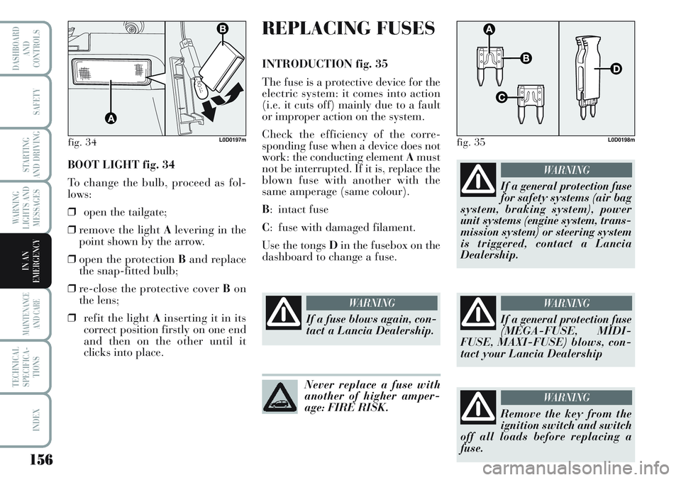
BOOT LIGHT fig. 34
To change the bulb, proceed as fol-
lows:
❒open the tailgate;
❒remove the light Alevering in the
point shown by the arrow.
❒open the protection Band replace
the snap-fitted bulb;
❒re-close the protective cover Bon
the lens;
❒refit the light Ainserting it in its
correct position firstly on one end
and then on the other until it
clicks into place.
fig. 34L0D0197m
REPLACING FUSES
INTRODUCTION fig. 35
The fuse is a protective device for the
electric system: it comes into action
(i.e. it cuts off) mainly due to a fault
or improper action on the system.
Check the efficiency of the corre-
sponding fuse when a device does not
work: the conducting element Amust
not be interrupted. If it is, replace the
blown fuse with another with the
same amperage (same colour).
B: intact fuse
C: fuse with damaged filament.
Use the tongs Din the fusebox on the
dashboard to change a fuse.
fig. 35L0D0198m
If a fuse blows again, con-
tact a Lancia Dealership.
WARNING
Never replace a fuse with
another of higher amper-
age: FIRE RISK.
If a general protection fuse
(MEGA-FUSE, MIDI-
FUSE, MAXI-FUSE) blows, con-
tact your Lancia Dealership
WARNING
Remove the key from the
ignition switch and switch
off all loads before replacing a
fuse.
WARNING
If a general protection fuse
for safety systems (air bag
system, braking system), power
unit systems (engine system, trans-
mission system) or steering system
is triggered, contact a Lancia
Dealership.
WARNING
Page 158 of 218
157
WARNING
LIGHTS AND
MESSAGES
MAINTENANCE
AND CARE
TECHNICAL
SPECIFICA-
TIONS
INDEX
DASHBOARD
AND
CONTROLS
SAFETY
STARTING
AND DRIVING
IN AN
EMERGENCY
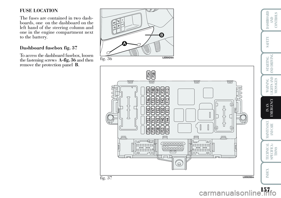
FUSE LOCATION
The fuses are contained in two dash-
boards, one on the dashboard on the
left hand of the steering column and
one in the engine compartment next
to the battery.
Dashboard fusebox fig. 37
To access the dashboard fusebox, loosen
the fastening screws A-fig. 36and then
remove the protection panel B.
L0D0200m
fig. 36L0D0424m
fig. 37