warning light Lancia Thema 2012 Owner handbook (in English)
[x] Cancel search | Manufacturer: LANCIA, Model Year: 2012, Model line: Thema, Model: Lancia Thema 2012Pages: 316, PDF Size: 3.85 MB
Page 69 of 316

MIRRORS
AUTOMATIC DIMMING
MIRROR
This mirror automatically adjusts for
headlight glare from vehicles behind
you.
NOTE:
This feature is disabled when the
vehicle is moving in reverse.CAUTION!
To avoid damage to the mirror dur-
ing cleaning, never spray any clean-
ing solution directly onto the mirror.
Apply the solution onto a clean cloth
and wipe the mirror clean.OUTSIDE MIRRORS
To receive maximum benefit, adjust
the outside mirror(s) to center on the
adjacent lane of traffic and a slight
overlap of the view obtained from the
inside mirror.
NOTE:
The passenger side convex outside
mirror will give a much wider view
to the rear, and especially of the
lane next to your vehicle.
WARNING!
Vehicles and other objects seen in
the passenger side convex mirror
will look smaller and farther away
than they really are. Relying too
much on your passenger side convex
mirror could cause you to collide
with another vehicle or other object.
Use your inside mirror when judging
the size or distance of a vehicle seen
in the passenger side convex mirror.
OUTSIDE MIRRORS
FOLDING FEATURE
Vehicles are equipped with mirrors
that are hinged. The hinge allows the
mirror to pivot forward and rearward to resist damage. The hinge has three
detent positions: full forward, full
rearward and normal.
DRIVER'S AUTOMATIC
DIMMING MIRROR (for
versions/markets, where
provided)
The driver’s outside mirror will auto-
matically adjust for glare from ve-
hicles behind you. This feature is con-
trolled by the inside automatic
dimming mirror and can be turned on
or off by pressing the button at the
base of the inside mirror. The mirror
will automatically adjust for head-
light glare when the inside mirror ad-
justs.
OUTSIDE MIRRORS WITH
TURN SIGNAL AND
APPROACH LIGHTING (for
versions/markets, where
provided)
Driver and passenger outside mirrors
with turn signals located within the
mirror housing and approach lighting
located within mirror glass contain
five LEDs.
Automatic Dimming Mirror
63
Page 70 of 316

Three of the LEDs are turn signal
indicators, which flash with the corre-
sponding turn signal lights in the
front and rear of the vehicle. Turning
on the Hazard Warning flashers will
also activate these LEDs.
The other two LEDs supply illumi-
nated entry lighting, which turns on
in both mirrors when you use the Re-
mote Keyless Entry (RKE) transmit-
ter or open any door. These LEDs
shine outward to illuminate the front
and rear door handles. They also
shine downward to illuminate the
area in front of the doors.
The Illuminated Entry lighting fades
to off after about 30 seconds or it will
fade to off immediately once the igni-
tion is placed into the RUN position.
NOTE:
The approach lighting will not
function when the shift lever is
moved out of the PARK position.TILT MIRRORS IN
REVERSE (for
versions/markets, where
provided)
Tilt Mirrors in Reverse provides auto-
matic outside mirror positioning
which will aid the driver’s view of the
ground rearward of the front doors.
The outside mirrors will move slightly
downward from the present position
when the vehicle is shifted into RE-
VERSE. The outside mirrors will then
return to the original position when
the vehicle is shifted out of the RE-
VERSE position. Each stored
memory setting will have an associ-
ated Tilt Mirrors in Reverse position.
NOTE:
The Tilt Mirrors in Reverse feature
can be turned on and off using the
Uconnect Touch™ System, refer to
“Uconnect Touch™ Settings” in
“Understanding Your Instrument
Panel” for further information.POWER MIRRORS
The power mirror controls are located
on the driver's door trim panel.
The power mirror controls consist of
mirror select buttons and a four-way
mirror control switch. To adjust a mir-
ror, press either the L (left) or R
(right) button to select the mirror that
you want to adjust.
NOTE:
A light in the select button will
illuminate indicating the mirror is
activated and can be adjusted.
Using the mirror control switch, press
on any of the four arrows for the di-
rection that you want the mirror to
move.
Power Mirror Control
64
Page 72 of 316

BLIND SPOT
MONITORING (for
versions/markets, where
provided)
The Blind Spot Monitoring (BSM)
system uses two radar-based sensors,
located inside the rear bumper fascia,
to detect highway licensable vehicles
(automobiles, trucks, motorcycles,
etc.) that enter the blind spot zones
from the rear/front/side of the ve-
hicle.
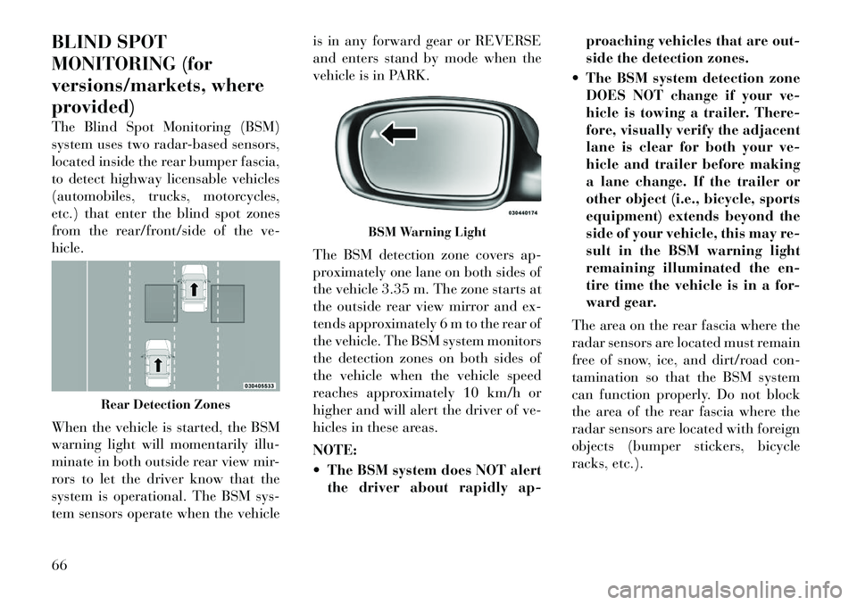
When the vehicle is started, the BSM
warning light will momentarily illu-
minate in both outside rear view mir-
rors to let the driver know that the
system is operational. The BSM sys-
tem sensors operate when the vehicleis in any forward gear or REVERSE
and enters stand by mode when the
vehicle is in PARK.
The BSM detection zone covers ap-
proximately one lane on both sides of
the vehicle 3.35 m. The zone starts at
the outside rear view mirror and ex-
tends approximately 6 m to the rear of
the vehicle. The BSM system monitors
the detection zones on both sides of
the vehicle when the vehicle speed
reaches approximately 10 km/h or
higher and will alert the driver of ve-
hicles in these areas.
NOTE:
The BSM system does NOT alert
the driver about rapidly ap- proaching vehicles that are out-
side the detection zones.
The BSM system detection zone DOES NOT change if your ve-
hicle is towing a trailer. There-
fore, visually verify the adjacent
lane is clear for both your ve-
hicle and trailer before making
a lane change. If the trailer or
other object (i.e., bicycle, sports
equipment) extends beyond the
side of your vehicle, this may re-
sult in the BSM warning light
remaining illuminated the en-
tire time the vehicle is in a for-
ward gear.
The area on the rear fascia where the
radar sensors are located must remain
free of snow, ice, and dirt/road con-
tamination so that the BSM system
can function properly. Do not block
the area of the rear fascia where the
radar sensors are located with foreign
objects (bumper stickers, bicycle
racks, etc.).
Rear Detection Zones
BSM Warning Light
66
Page 73 of 316

The BSM system notifies the driver of
objects in the detection zones by illu-
minating the BSM warning light lo-
cated in the outside mirrors in addi-
tion to sounding an audible (chime)
alert and reducing the radio volume.
Refer to “Modes Of Operation” for
further information.
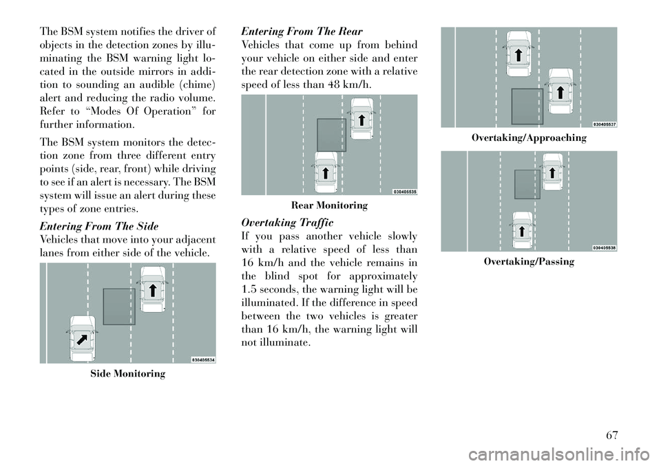
The BSM system monitors the detec-
tion zone from three different entry
points (side, rear, front) while driving
to see if an alert is necessary. The BSM
system will issue an alert during these
types of zone entries.
Entering From The Side
Vehicles that move into your adjacent
lanes from either side of the vehicle.Entering From The Rear
Vehicles that come up from behind
your vehicle on either side and enter
the rear detection zone with a relative
speed of less than 48 km/h.
Overtaking Traffic
If you pass another vehicle slowly
with a relative speed of less than
16 km/h and the vehicle remains in
the blind spot for approximately
1.5 seconds, the warning light will be
illuminated. If the difference in speed
between the two vehicles is greater
than 16 km/h, the warning light will
not illuminate.
Side Monitoring
Rear Monitoring
Overtaking/Approaching
Overtaking/Passing
67
Page 75 of 316

WARNING!
RCP is not a Back Up Aid system. It
is intended to be used to help a
driver detect an oncoming vehicle in
a parking lot situation. Drivers must
be careful when backing up, even
when using RCP. Always check care-
fully behind your vehicle, look be-
hind you, and be sure to check for
pedestrians, animals, other vehicles,
obstructions, and blind spots before
backing up. Failure to do so can
result in serious injury or death.
MODES OF OPERATION
Three selectable modes of operation
are available in the Uconnect Touch™
System. Refer to “Uconnect Touch™
Settings” in “Understanding Your In-
strument Panel” for further informa-
tion. Blind Spot Alert
When operating in Blind Spot Alert
mode, the BSM system will provide a
visual alert in the appropriate side
view mirror based on a detected ob-
ject. However, when the system is op-
erating in RCP, the system will re-
spond with both visual and audible
alerts when a detected object is pres-
ent. Whenever an audible alert is re-
quested, the radio volume is reduced.
Blind Spot Alert Lights/Chime
When operating in Blind Spot Alert
Lights/Chime mode, the BSM system
will provide a visual alert in the ap-
propriate side view mirror based on a
detected object. If the turn signal is
then activated, and it corresponds to
an alert present on that side of the
vehicle, an audible chime will also be
sounded. Whenever a turn signal and
detected object are present on the
same side at the same time, both the
visual and audio alerts will be issued.
In addition to the audible alert, the
radio (if on) volume will be reduced.NOTE:
Whenever an audible alert is re-
quested by the BSM system, the
radio volume is reduced.
If the hazard flashers are on, the system will request the appro-
priate visual alert only.
When the system is in RCP, the
system shall respond with both vi-
sual and audible alerts when a de-
tected object is present. Whenever
an audible alert is requested, the
radio is also muted. Turn/hazard
signal status is ignored; the RCP
state always requests the audible
chime.
Blind Spot Alert Off
When the BSM system is turned off,
there will be no visual or audible
alerts from either the BSM or RCP
systems.
NOTE:
The BSM system will store the cur-
rent operating mode when the ve-
hicle is shut off. Each time the ve-
hicle is started, the previously
stored mode will be recalled and
used.
69
Page 86 of 316

UCONNECT™ PHONE
FEATURES
Emergency Assistance
If you are in an emergency and the
mobile phone is reachable:
Pick up the phone and manuallydial the emergency number for
your area.
If the phone is not reachable and the
Uconnect™ Phone is operational, you
may reach the emergency number as
follows:
Press the
button to begin.
After the “Listening” prompt and the following beep, say “Call Emer-
gency or Dial Emergency” and the
Uconnect™ Phone will instruct the
paired mobile phone to call the
emergency number. This feature is
supported in the U.S., Canada, and
Mexico.
NOTE:
The Emergency call may also be initiated by using the touch-
screen.
The emergency number dialed is based on the country where the vehicle is purchased. The num-
ber dialed may not be appli-
cable with the available mobile
service and area.
The Uconnect™ Phone does slightly lower your chances of
successfully making a phone
call as to that for the mobile
phone directly.
WARNING!
Your phone must be turned on and
connected to the Uconnect™ Phone
to allow use of this vehicle feature in
emergency situations, when the mo-
bile phone has network coverage
and stays connected to the
Uconnect™ Phone.
Towing Assistance
If you need towing assistance:
Press the
button to begin.
After the “Listening” prompt and the following beep, say “Towing
Assistance”.
NOTE:
The towing assistance call may also be initiated by touch. The towing assistance number
dialed is based on the country
where the vehicle is purchased.
Please refer to the LANCIA 24-
Hour “Towing Assistance” cov-
erage details in the Warranty In-
formation Booklet and on the
24–Hour Towing Assistance
Card.
Voice Mail Calling
To learn how to access your voice
mail, refer to “Working with Auto-
mated Systems”.
Working With Automated Systems
This method is used in instances
where one generally has to press num-
bers on the mobile phone keypad
while navigating through an auto-
mated telephone system.
You can use your Uconnect™ Phone
to access a voice mail system or an
automated service, such as a paging
service or automated customer service
line. Some services require immediate
response selection. In some instances,
that may be too quick for use of the
Uconnect™ Phone.
80
Page 110 of 316

in “Understanding Your Instru-
ment Panel” for further informa-
tion.
TO OPEN AND CLOSE
THE HOOD
Two latches must be released to open
the hood.
1. Pull the hood release lever located
under the left side of the instrument
panel.
2. Move to the outside of the vehicle
and push the safety catch to the left.
The safety catch is located under the
center front edge of the hood.NOTE:
Your vehicle may be equipped with
an Active Hood System. Refer to
“Occupant Restraints” in “Things
To Know Before Starting Your Ve-
hicle” for further information.
CAUTION!
To prevent possible damage, do not
slam the hood to close it. Lower the
hood, until it is open approximately
15 cm, and then drop it. This should
secure both latches. Never drive
your vehicle unless the hood is fully
closed, with both latches engaged.
WARNING!
Be sure the hood is fully latched
before driving your vehicle. If the
hood is not fully latched, it could
open when the vehicle is in motion
and block your vision. Failure to
follow this warning could result in
serious injury or death.
LIGHTS
HEADLIGHT SWITCH The headlight switch is located
on the left side of the instru-
ment panel. This switch con-
trols the operation of the headlights,
parking lights, instrument panel
lights, instrument panel light dim-
ming, interior lights and fog lights.
NOTE:
In certain European countries, the
parking light feature will only op-
erate with the ignition OFF, or with
either the fog lamps or headlights
also ON. Regardless of ignition
switch position, the parking lights
will remain ON as long as the
switch is in this first detent.
Hood Release Lever
Hood Safety Latch
104
Page 117 of 316

WINDSHIELD WASHERS
To use the washer, push the multi-
function lever inward (toward the
steering column) and hold it for as
long as washer spray is desired.
If you activate the washer while the
windshield wiper control is in the de-
lay range, the wipers will operate for
two wipe cycles after releasing the
lever and then resume the intermit-
tent interval previously selected.
If you activate the washer while the
windshield wiper is turned off, the
wipers will operate for three wipe
cycles and then turn off.WARNING!
Sudden loss of visibility through the
windshield could lead to a collision.
You might not see other vehicles or
other obstacles. To avoid sudden ic-
ing of the windshield during freezing
weather, warm the windshield with
the defroster before and during
windshield washer use.HEADLIGHTS ON WITH
WIPERS (Available With
Automatic Headlights Only)
When this feature is active, the head-
lights will turn on approximately
10 seconds after the wipers are turned
on if the headlight switch is placed in
the AUTO position. In addition, the
headlights will turn off when the wip-
ers are turned off if they were turned
on by this feature.
The Headlights On with Wipers fea-
ture can be turned on and off using
the Uconnect Touch™ System, refer
to “Uconnect Touch™ Settings” in
“Understanding Your Instrument
Panel” for further information.
RAIN SENSING WIPERS
(for versions/markets,
where provided)
This feature senses moisture on the
windshield and automatically acti-
vates the wipers for the driver. The
feature is especially useful for road
splash or over spray from the wind-
shield washers of the vehicle ahead. Rotate the end of the multifunction
lever to one of four settings to activate
this feature.
The sensitivity of the system can be
adjusted with the multifunction lever.
Wiper delay position 1 is the least
sensitive, and wiper delay position 4 is
the most sensitive. Setting 3 should be
used for normal rain conditions. Set-
tings 1 and 2 can be used if the driver
desires less wiper sensitivity. Settings
4 can be used if the driver desires
more sensitivity. The rain sense wip-
ers will automatically change between
an intermittent wipe, slow wipe and a
fast wipe depending on the amount of
moisture that is sensed on the wind-
shield. Place the wiper switch in the
OFF position when not using the sys-
tem.
The Rain Sensing feature can be
turned on and off using the Uconnect
Touch™ System, refer to “Uconnect
Touch™ Settings” in “Understanding
Your Instrument Panel” for further
information.
111
Page 122 of 316

NOTE:
In order to ensure proper opera-
tion, the Electronic Speed Control
System has been designed to shut
down if multiple Speed Control
functions are operated at the same
time. If this occurs, the Electronic
Speed Control System can be reac-
tivated by pushing the Electronic
Speed Control ON/OFF button and
resetting the desired vehicle set
speed.
TO ACTIVATE
Push the ON/OFF button. The Cruise
Indicator Light in the Electronic Ve-
hicle Information Center (EVIC) will
illuminate. To turn the system off,
push the ON/OFF button a second
time. The Cruise Indicator Light will
turn off. The system should be turned
off when not in use.
WARNING!
Leaving the Electronic Speed Con-
trol system on when not in use is
dangerous. You could accidentally
set the system or cause it to go faster
than you want. You could lose con-
trol and have an accident. Always
leave the system OFF when you are
not using it.
TO SET A DESIRED SPEED
Turn the Electronic Speed Control
ON. When the vehicle has reached the
desired speed, press the SET (-) but-
ton and release. Release the accelera-
tor and the vehicle will operate at the
selected speed.
NOTE:
The vehicle should be traveling at
a steady speed and on level ground
before pressing the SET button.
TO DEACTIVATE
A soft tap on the brake pedal, pushing
the CANCEL button, or normal brake
pressure while slowing the vehicle will
deactivate Electronic Speed Control
without erasing the set speed memory. Pressing the ON/OFF button or turn-
ing the ignition switch OFF erases the
set speed memory.
TO RESUME SPEED
To resume a previously set speed,
push the RES (+) button and release.
Resume can be used at any speed
above 32 km/h.
TO VARY THE SPEED
SETTING
When the Electronic Speed Control is
set, you can increase speed by pushing
the RES (+) button. If the button is
continually pressed, the set speed will
continue to increase until the button is
released, then the new set speed will
be established.
Pressing the RES (+) button once will
result in the following set speeds:
2.0 km/h (3.0L Diesel Engine)
1.6 km/h (3.6L Engine)
Each subsequent tap of the button
results in an increase of 2.0 km/h
(3.0L Diesel Engine) or 1.6 km/h
(3.6L Engine).
116
Page 123 of 316

To decrease speed while the Elec-
tronic Speed Control is set, push the
SET (-) button. If the button is con-
tinually held in the SET (-) position,
the set speed will continue to decrease
until the button is released. Release
the button when the desired speed is
reached, and the new set speed will be
established.
Pressing the SET (-) button once will
result in the following decrease in set
speed:
2.0 km/h (3.0L Diesel Engine)
1.6 km/h (3.6L Engine)
Each subsequent tap of the button
results in a decrease of 2.0 km/h
(3.0L Diesel Engine) or 1.6 km/h
(3.6L Engine)
TO ACCELERATE FOR
PASSING
Press the accelerator as you would
normally. When the pedal is released,
the vehicle will return to the set speed.
Using Electronic Speed Control
On Hills
The transmission may downshift on
hills to maintain the vehicle set speed.NOTE:
The Electronic Speed Control sys-
tem maintains speed up and down
hills. A slight speed change on
moderate hills is normal.
On steep hills, a greater speed loss or
gain may occur so it may be prefer-
able to drive without Electronic Speed
Control.
WARNING!
Electronic Speed Control can be
dangerous where the system cannot
maintain a constant speed. Your ve-
hicle could go too fast for the condi-
tions, and you could lose control and
have an accident. Do not use Elec-
tronic Speed Control in heavy traffic
or on roads that are winding, icy,
snow-covered or slippery.
ADAPTIVE CRUISE
CONTROL (ACC) (for
versions/markets, where
provided)
Adaptive Cruise Control (ACC) in-
creases the driving convenience pro-
vided by cruise control while traveling on highways and major roadways.
However, it is not a safety system and
not designed to prevent collisions.
ACC will allow you to keep cruise
control engaged in light to moderate
traffic conditions without the con-
stant need to reset your cruise control.
ACC utilizes a radar sensor designed
to detect a vehicle directly ahead of
you.
NOTE:
If the sensor does not detect a
vehicle ahead of you, ACC will
maintain a fixed set speed.
If the ACC sensor detects a ve- hicle ahead, ACC will apply lim-
ited braking or acceleration (not
to exceed the original set speed)
automatically to maintain a pre-
set following distance, while
matching the speed of the ve-
hicle ahead.
117