Instrument panel Lancia Thema 2012 Owner handbook (in English)
[x] Cancel search | Manufacturer: LANCIA, Model Year: 2012, Model line: Thema, Model: Lancia Thema 2012Pages: 316, PDF Size: 3.85 MB
Page 217 of 316

ESC Operating Modes
The ESC system has two available
operating modes:
ESC On
This is the normal operating mode for
the ESC. Whenever the vehicle is
started, the ESC system will be in this
mode. This mode should be used for
most driving conditions. The ESC
should only be turned OFF for spe-
cific reasons as noted in the following
paragraphs.
Partial Off
The “Partial Off” mode is intended
for times when a more spirited driving
experience is desired. It is also in-
tended for driving in deep snow, sand,
or gravel. This mode disables the TCS
portion of the ESC and raises the
threshold for ESC activation, which
allows for more wheel spin than what
ESC normally allows.
The “ESC Off” switch is located on
the switch bank in the center of the
instrument panel. To enter the “Par-tial Off” mode, momentarily press the
“ESC Off” switch and the “ESC
Activation/Malfunction Indicator
Light” will illuminate. To turn the
ESC on again, momentarily press the
“ESC Off” switch and the “ESC
Activation/Malfunction Indicator
Light” will turn off.
NOTE:
When in “Partial Off” mode, the
TCS functionality of ESC, (ex-
cept for the limited slip feature
described in the TCS section),
has been disabled and the “ESC
Off Indicator Light” will be illu-
minated. All other stability fea-
tures of ESC function normally.
When in “Partial Off” mode, the
engine power reduction feature
of TCS is disabled, and the en-
hanced vehicle stability offered
by the ESC system is reduced.
To improve the vehicle's traction when driving with snow chains,
or when starting off in deep
snow, sand, or gravel, it may be desirable to switch to the “Par-
tial Off” mode by momentarily
pressing the “ESC Off” switch.
Once the situation requiring
“Partial Off” mode is overcome,
turn the ESC on again by mo-
mentarily pressing the “ESC Off”
switch. This may be done while
the vehicle is in motion.
HILL START ASSIST (HSA)
The HSA system is designed to assist
the driver when starting a vehicle
from a stop on a hill. HSA will main-
tain the level of brake pressure the
driver applied for a short period of
time after the driver takes their foot
off of the brake pedal. If the driver
does not apply the throttle during this
short period of time, the system will
release brake pressure and the vehicle
will roll down the hill. The system will
release brake pressure in proportion
to the amount of throttle applied as
the vehicle starts to move in the in-
tended direction of travel.
211
Page 218 of 316

HSA Activation Criteria
The following criteria must be met in
order for HSA to activate:
Vehicle must be stopped.
Vehicle must be on a 6% (approxi-mate) grade or greater hill.
Gear selection matches vehicle up- hill direction (i.e., vehicle facing
uphill is in forward gear; vehicle
backing uphill is in REVERSE
gear).
HSA will work in REVERSE and all
forward gears when the activation cri-
teria have been met. The system will
not activate if the vehicle is placed in
NEUTRAL or PARK.WARNING!
There may be situations on minor
hills (i.e., less than 8%), with a
loaded vehicle, or while pulling a
trailer, when the system will not ac-
tivate and slight rolling may occur.
This could cause a collision with an-
other vehicle or object. Always re-
member the driver is responsible for
braking the vehicle. Towing With HSA
HSA will provide assistance when
starting on a grade when pulling a
trailer.
WARNING!
If you use a trailer brake control-
ler with your trailer, your trailer
brakes may be activated and de-
activated with the brake switch. If
so, when the brake pedal is re-
leased, there may not be enough
brake pressure to hold the vehicle
and trailer on a hill and this could
cause a collision with another ve-
hicle or object behind you. In or-
der to avoid rolling down the hill
while resuming acceleration,
manually activate the trailer
brake prior to releasing the brake
pedal. Always remember the
driver is responsible for braking
the vehicle.
HSA is not a parking brake. Al-
ways apply the parking brake
fully when leaving your vehicle.
Also, be certain to leave the trans-
mission in PARK.
(Continued)
WARNING!(Continued)
Failure to follow these warnings
may cause the vehicle to roll down
the incline and could collide with
another vehicle, object or person,
and cause serious or fatal injury.
Always remember to use the park-
ing brake while parking on a hill
and that the driver is responsible
for braking the vehicle.
HSA Off
If you wish to turn off the HSA sys-
tem, it can be done using the Cus-
tomer Programmable Features in the
Uconnect Touch™ System. Refer to
“Uconnect TOUCH™ SETTINGS” in
“Understanding Your Instrument
Panel” for further information.
READY ALERT BRAKING
Ready Alert Braking may reduce the
time required to reach full braking
during emergency braking situations.
It anticipates when an emergency
braking situation may occur by moni-
toring how fast the throttle is released
by the driver. When the throttle is
released very quickly, Ready Alert
Braking applies a small amount of
212
Page 246 of 316

HAZARD WARNING
FLASHERS
The Hazard Warning flasher switch is
located in the center of the instrument
panel between the center air outlets.Press the switch to turn on the
Hazard Warning flashers.
When the switch is activated,
all directional turn signals will flash
on and off to warn oncoming traffic of
an emergency. Press the switch a sec-
ond time to turn off the Hazard Warn-
ing flashers.
This is an emergency warning system
and it should not be used when the
vehicle is in motion. Use it when your
vehicle is disabled and it is creating a
safety hazard for other motorists.
When you must leave the vehicle to
seek assistance, the Hazard Warning
flashers will continue to operate even
though the ignition is placed in the
OFF position. NOTE:
With extended use the Hazard
Warning flashers may wear down
your battery.
IF YOUR ENGINE
OVERHEATS
In any of the following situations, you
can reduce the potential for overheat-
ing by taking the appropriate action.
On the highways — slow down.
In city traffic — while stopped,
place the transmission in NEU-
TRAL, but do not increase the en-
gine idle speed.
NOTE:
There are steps that you can take to
slow down an impending overheat
condition:
If your air conditioner (A/C) is on, turn it off. The A/C system
adds heat to the engine cooling
system and turning the A/C off
can help remove this heat.
You can also turn the tempera- ture control to maximum heat,
the mode control to floor and the blower control to high. This al-
lows the heater core to act as a
supplement to the radiator and
aids in removing heat from the
engine cooling system.
CAUTION!
Driving with a hot cooling system
could damage your vehicle. If the
temperature gauge reads “H,” pull
over and stop the vehicle. Idle the
vehicle with the air conditioner
turned off until the pointer drops
back into the normal range. If the
pointer remains on the “H,” turn the
engine off immediately and call for
service.WARNING!
You or others can be badly burned
by hot engine coolant (antifreeze) or
steam from your radiator. If you see
or hear steam coming from under
the hood, do not open the hood until
the radiator has had time to cool.
Never try to open a cooling system
pressure cap when the radiator or
coolant bottle is hot.
240
Page 297 of 316

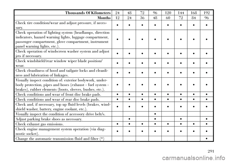
Thousands Of Kilometers24 48 72 96 120 144 168 192
Months 12 24 36 48 60 72 84 96
Check tire condition/wear and adjust pressure, if neces-
sary.
Check operation of lighting system (headlamps, direction
indicators, hazard warning lights, luggage compartment,
passenger compartment, glove compartment, instrument
panel warning lights, etc.).
Check operation of windscreen washer system and adjust
jets if necessary.
Check windshield/rear window wiper blade position/
wear.
Check cleanliness of hood and tailgate locks and cleanli-
ness and lubrication of linkages.
Visually inspect condition of: exterior bodywork, under-
body protection, pipes and hoses (exhaust - fuel system -
brakes), rubber elements (boots, sleeves, bushes, etc.).
Check conditions and wear of front disc brake pads.
Check conditions and wear of rear disc brake pads.
Check and, if necessary, top up fluid levels (brakes, wind-
shield washer, battery, engine coolant, etc.).
Visually inspect the condition of accessory drive belt/s.
Adjust parking brake shoes as necessary.
Check exhaust gas emissions.
Check engine management system operation (via diag-
nostic socket).
Change the automatic transmission fluid and filter (*)
291
Page 299 of 316

check and, if necessary, replace pol-len filter;
check and, if necessary, replace air cleaner filter.
MAINTENANCE
SCHEDULE – DIESEL
ENGINE
To help you have the best driving
experience possible, the manufacturer
has identified the specific vehicle
maintenance service intervals that are
required to keep your vehicle operat-
ing properly and safely. The manufacturer recommends that
these maintenance intervals be per-
formed at your selling dealer. The
technicians at your dealership know
your vehicle best, and have access to
factory trained information, genuine
LANCIA parts, and specially designed
electronic and mechanical tools that
can help prevent future costly repairs.
The maintenance intervals shown
should be performed as indicated in
this section.
NOTE:
Under no circumstances should oil
change intervals exceed 20 000 km
or 12 months, whichever comes
first.
CAUTION!
Failure to perform the required
maintenance items may result in
damage to the vehicle.
Required Maintenance Intervals
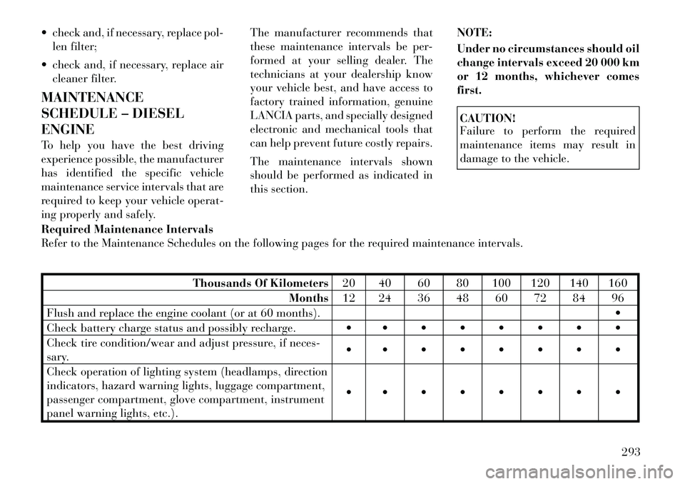
Refer to the Maintenance Schedules on the following pages for the required maintenance intervals.
Thousands Of Kilometers 20 40 60 80 100 120 140 160
Months 12 24 36 48 60 72 84 96
Flush and replace the engine coolant (or at 60 months).
Check battery charge status and possibly recharge.
Check tire condition/wear and adjust pressure, if neces-
sary.
Check operation of lighting system (headlamps, direction
indicators, hazard warning lights, luggage compartment,
passenger compartment, glove compartment, instrument
panel warning lights, etc.).
293
Page 307 of 316

Fog Lights, Rear . . . . . . . . . . 107
Folding Rear Seat . . . . . . . . . 101
Forward Collision
Warning . . . . . . . . . . . . . 128,162
Freeing A Stuck Vehicle . . . . . 248
Fuel . . . . . . . . . . . . . . . . 223,225Additives . . . . . . . . . . . . . . 224
Conserving . . . . . . . . . . . . 165
Diesel . . . . . . . . . . . . . . . . 225
Filler Door (Gas Cap) . . . . . 156
Gasoline . . . . . . . . . . . . . . 223
Gauge . . . . . . . . . . . . . . . . 156
Light . . . . . . . . . . . . . . . . . 162
Octane Rating . . . . . . . 223,284
Saver Mode . . . . . . . . . . . . 165
Specifications . . . . . . . . . . . 284
Tank Capacity . . . . . . . . . . 283
Fuel Optimizer . . . . . . . . . . . 165
Fuel Saver . . . . . . . . . . . . . . . 165
Fuses . . . . . . . . . . . . . . . . . . 274
Gasoline (Fuel) . . . . . . . . . . . 223 Conserving . . . . . . . . . . . . 165
Gasoline, Clean Air . . . . . . . . 224
Gauges Coolant Temperature . . . . . 159
Fuel . . . . . . . . . . . . . . . . . 156
Speedometer . . . . . . . . . . . 156
Tachometer . . . . . . . . . . . . 154 Gear Ranges . . . . . . . . . . 196,200
Gear Select Lever Override . . . 249
General Information . . . . 14,18,88
General Maintenance . . . . . . . 257
Glass Cleaning . . . . . . . . . . . . 273
Gross Axle Weight Rating
. . 227,229
Gross Vehicle Weight
Rating
. . . . . . . . . . . . . . 227,228
GVWR . . . . . . . . . . . . . . . . . 227
Hazard Driving Through Flowing,
Rising, or Shallow Standing
Water . . . . . . . . . . . . . . . . 204
Hazard Warning Flasher . . . . . 240
Head Restraints . . . . . . . . . . . . 99
Head Rests . . . . . . . . . . . . . . . 99
Headlight Washers . . . . . 112,263
Headlights . . . . . . . . . . . . . . 281
Automatic . . . . . . . . . . . . . 105
Bulb Replacement . . . . . . . 281
Cleaning . . . . . . . . . . . . . . 273
Delay . . . . . . . . . . . . . . . . 105
High Beam/Low Beam Select
Switch . . . . . . . . . . . . . . . . 107
Lights On Reminder . . . . . . 107
On With Wipers . . . . . . 105,111
Passing . . . . . . . . . . . . . . . 108
Switch . . . . . . . . . . . . . . . . 104 Time Delay . . . . . . . . . . . . 105
Washers . . . . . . . . . . . . . . . 112
Heated Mirrors . . . . . . . . . . . . 65
High Beam/Low Beam Select
(Dimmer) Switch . . . . . . . . . . 107
Hill Start Assist . . . . . . . . . . . 211
Holder, Coin . . . . . . . . . . . . . 143
Holder, Cup . . . . . . . . . . . . . 142
Ignition Key . . . . . . . . . . . . . . . . . . . 12
Illuminated Entry . . . . . . . . . . 16
Immobilizer (Sentry Key) . . . . . 13
Infant Restraint . . . . . . . . . 42,45
Information Center, Vehicle . . 159
Instrument Cluster . . . . . 153,154
Instrument Panel and
Controls . . . . . . . . . . . . . . . . 152
Instrument Panel Lens
Cleaning . . . . . . . . . . . . . . . . 273
Integrated Power Module
(Fuses) . . . . . . . . . . . . . . . . . 274
Interior Appearance Care . . . . 272
Interior Fuses . . . . . . . . . . . . 274
Interior Lights . . . . . . . . . . . . 108
Intermittent Wipers (Delay
Wipers) . . . . . . . . . . . . . . . . . 110
Intervention Regeneration
Strategy . . . . . . . . . . . . . . . . 264
301