ABS Lancia Thema 2012 Owner handbook (in English)
[x] Cancel search | Manufacturer: LANCIA, Model Year: 2012, Model line: Thema, Model: Lancia Thema 2012Pages: 316, PDF Size: 3.85 MB
Page 31 of 316
With the ignition in the ON/RUN po-
sition, the Trunk Open symbol will
display in the instrument cluster indi-
cating that the trunk is open. The
odometer display will reappear once
the trunk is closed.
With the ignition in the OFF position,
the Trunk Open symbol will display
until the trunk is closed.
Refer to “Keyless Enter-N-Go” in
“Things To Know Before Starting
Your Vehicle” for more information
on trunk operation with the Passive
Entry feature.
TRUNK SAFETY
WARNINGWARNING!Do not allow children to have access to
the trunk, either by climbing into the
trunk from outside, or through the
inside of the vehicle. Always close the
trunk lid when your vehicle is unat-
tended. Once in the trunk, young chil-
dren may not be able to escape, even if
they entered through the rear seat. If
trapped in the trunk, children can die
from suffocation or heat stroke.
TRUNK EMERGENCY
RELEASE
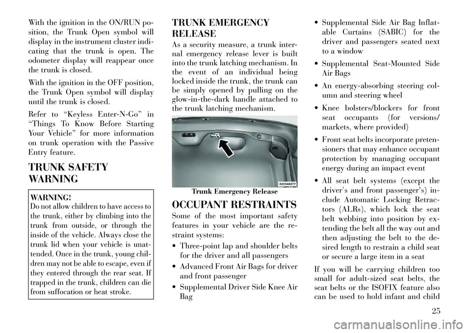
As a security measure, a trunk inter-
nal emergency release lever is built
into the trunk latching mechanism. In
the event of an individual being
locked inside the trunk, the trunk can
be simply opened by pulling on the
glow-in-the-dark handle attached to
the trunk latching mechanism.
OCCUPANT RESTRAINTS
Some of the most important safety
features in your vehicle are the re-
straint systems:
Three-point lap and shoulder beltsfor the driver and all passengers
Advanced Front Air Bags for driver and front passenger
Supplemental Driver Side Knee Air Bag Supplemental Side Air Bag Inflat-
able Curtains (SABIC) for the
driver and passengers seated next
to a window
Supplemental Seat-Mounted Side Air Bags
An energy-absorbing steering col- umn and steering wheel
Knee bolsters/blockers for front seat occupants (for versions/
markets, where provided)
Front seat belts incorporate preten- sioners that may enhance occupant
protection by managing occupant
energy during an impact event
All seat belt systems (except the driver’s and front passenger's) in-
clude Automatic Locking Retrac-
tors (ALRs), which lock the seat
belt webbing into position by ex-
tending the belt all the way out and
then adjusting the belt to the de-
sired length to restrain a child seat
or secure a large item in a seat
If you will be carrying children too
small for adult-sized seat belts, the
seat belts or the ISOFIX feature also
can be used to hold infant and child
Trunk Emergency Release
25
Page 126 of 316
WARNING!
Leaving the Adaptive Cruise Control
(ACC) system on when not in use is
dangerous. You could accidentally
set the system or cause it to go faster
than you want. You could lose con-
trol and have a collision. Always
leave the system off when you are
not using it.
TO SET A DESIRED ACC
SPEED
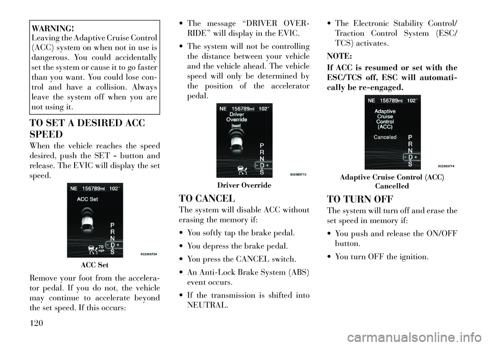
When the vehicle reaches the speed
desired, push the SET -button and
release. The EVIC will display the set
speed.
Remove your foot from the accelera-
tor pedal. If you do not, the vehicle
may continue to accelerate beyond
the set speed. If this occurs: The message “DRIVER OVER-
RIDE” will display in the EVIC.
The system will not be controlling the distance between your vehicle
and the vehicle ahead. The vehicle
speed will only be determined by
the position of the accelerator
pedal.
TO CANCEL
The system will disable ACC without
erasing the memory if:
You softly tap the brake pedal.
You depress the brake pedal.
You press the CANCEL switch.
An Anti-Lock Brake System (ABS) event occurs.
If the transmission is shifted into NEUTRAL. The Electronic Stability Control/
Traction Control System (ESC/
TCS) activates.
NOTE:
If ACC is resumed or set with the
ESC/TCS off, ESC will automati-
cally be re-engaged.
TO TURN OFF
The system will turn off and erase the
set speed in memory if:
You push and release the ON/OFF button.
You turn OFF the ignition.
ACC Set
Driver Override
Adaptive Cruise Control (ACC) Cancelled
120
Page 150 of 316
tissue boxes. In addition, the 12 volt
power outlet, USB and Aux jack are
located here.WARNING!
Do not operate this vehicle with a
console compartment lid in the open
position. Cellular phones, music
players, and other handheld elec-
tronic devices should be stowed
while driving. Use of these devices
while driving can cause an accident
due to distraction, resulting in death
or injury.
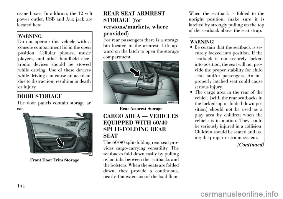
DOOR STORAGE
The door panels contain storage ar-
eas. REAR SEAT ARMREST
STORAGE (for
versions/markets, where
provided)
For rear passengers there is a storage
bin located in the armrest. Lift up-
ward on the latch to open the storage
compartment.
CARGO AREA — VEHICLES
EQUIPPED WITH 60/40
SPLIT-FOLDING REAR
SEAT
The 60/40 split-folding rear seat pro-
vides cargo-carrying versatility. The
seatbacks fold down easily by pulling
nylon tabs between the seatbacks and
the bolsters. When the seats are folded
down, they provide a continuous,
nearly-flat extension of the load floor.When the seatback is folded to the
upright position, make sure it is
latched by strongly pulling on the top
of the seatback above the seat strap.
WARNING!
Be certain that the seatback is se-
curely locked into position. If the
seatback is not securely locked
into position, the seat will not pro-
vide the proper stability for child
seats and/or passengers. An im-
properly latched seat could cause
serious injury.
The cargo area in the rear of the
vehicle (with the rear seatbacks in
the locked-up or folded down po-
sition) should not be used as a
play area by children when the
vehicle is in motion. They could
be seriously injured in a collision.
Children should be seated and us-
ing the proper restraint system.
(Continued)
Front Door Trim Storage
Rear Armrest Storage
144
Page 153 of 316

LOAD LEVELING
SYSTEM (for
versions/markets, where
provided)
The automatic load leveling system
will provide a level-riding vehicle un-
der most passenger and cargo loading
conditions.
A hydraulic pump contained within
the shock absorbers raises the rear of
the vehicle to the correct height. It
takes approximately 1.6 km of driv-
ing for the leveling to complete de-
pending on road surface conditions.
If the leveled vehicle is not moved for
approximately 15 hours, the leveling
system will bleed itself down. The ve-
hicle must be driven to reset the sys-
tem.147
Page 163 of 316

14. Brake Warning LightThis light monitors various
brake functions, including
brake fluid level and park-
ing brake application. If the
brake light turns on it may indicate
that the parking brake is applied, that
the brake fluid level is low, or that
there is a problem with the anti-lock
brake system reservoir.
If the light remains on when the park-
ing brake has been disengaged, and
the fluid level is at the full mark on the
master cylinder reservoir, it indicates
a possible brake hydraulic system
malfunction or that a problem with
the Brake Booster has been detected
by the Anti-Lock Brake System (ABS)
/ Electronic Stability Control (ESC)
system. In this case, the light will re-
main on until the condition has been
corrected. If the problem is related to
the brake booster, the ABS pump will
run when applying the brake and a
brake pedal pulsation may be felt dur-
ing each stop.
The dual brake system provides a re-
serve braking capacity in the event of
a failure to a portion of the hydraulic system. A leak in either half of the
dual brake system is indicated by the
Brake Warning Light, which will turn
on when the brake fluid level in the
master cylinder has dropped below a
specified level.
The light will remain on until the
cause is corrected.
NOTE:
The light may flash momentarily
during sharp cornering maneu-
vers, which change fluid level con-
ditions. The vehicle should have
service performed, and the brake
fluid level checked.
If brake failure is indicated, immedi-
ate repair is necessary.
WARNING!
Driving a vehicle with the red brake
light on is dangerous. Part of the
brake system may have failed. It will
take longer to stop the vehicle. You
could have a collision. Have the ve-
hicle checked immediately.
Vehicles equipped with the Anti-Lock
Brake System (ABS), are also
equipped with Electronic Brake Force Distribution (EBD). In the event of an
EBD failure, the Brake Warning Light
will turn on along with the ABS Light.
Immediate repair to the ABS system is
required.
Operation of the Brake Warning Light
can be checked by turning the ignition
switch from the OFF position to the
ON/RUN position. The light should
illuminate for approximately two sec-
onds. The light should then turn off
unless the parking brake is applied or
a brake fault is detected. If the light
does not illuminate, have the light
inspected by an authorized dealer.
The light also will turn on when the
parking brake is applied with the ig-
nition switch in the ON/RUN posi-
tion.
NOTE:
This light shows only that the
parking brake is applied. It does
not show the degree of brake ap-
plication.
157
Page 164 of 316
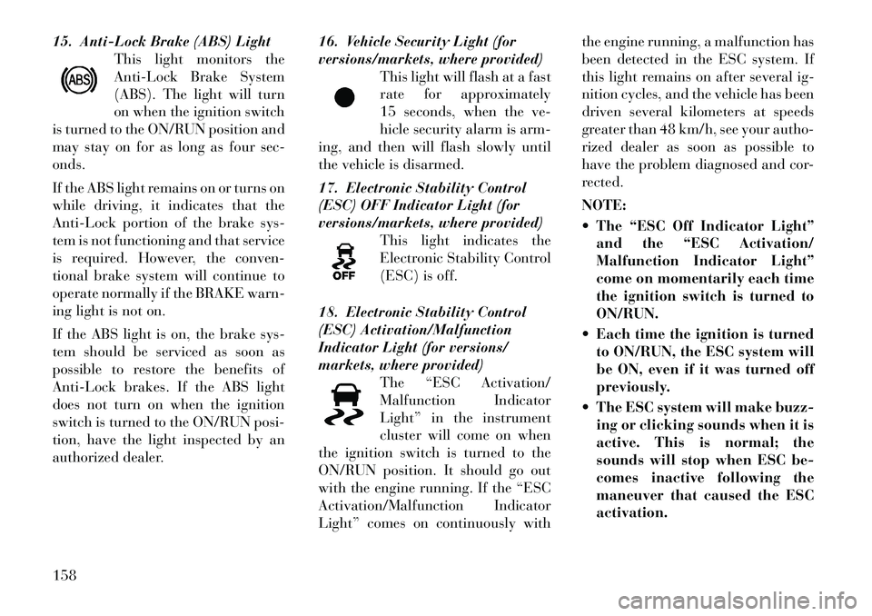
15. Anti-Lock Brake (ABS) LightThis light monitors the
Anti-Lock Brake System
(ABS). The light will turn
on when the ignition switch
is turned to the ON/RUN position and
may stay on for as long as four sec-
onds.
If the ABS light remains on or turns on
while driving, it indicates that the
Anti-Lock portion of the brake sys-
tem is not functioning and that service
is required. However, the conven-
tional brake system will continue to
operate normally if the BRAKE warn-
ing light is not on.
If the ABS light is on, the brake sys-
tem should be serviced as soon as
possible to restore the benefits of
Anti-Lock brakes. If the ABS light
does not turn on when the ignition
switch is turned to the ON/RUN posi-
tion, have the light inspected by an
authorized dealer. 16. Vehicle Security Light (for
versions/markets, where provided)
This light will flash at a fast
rate for approximately
15 seconds, when the ve-
hicle security alarm is arm-
ing, and then will flash slowly until
the vehicle is disarmed.
17. Electronic Stability Control
(ESC) OFF Indicator Light (for
versions/markets, where provided) This light indicates the
Electronic Stability Control
(ESC) is off.
18. Electronic Stability Control
(ESC) Activation/Malfunction
Indicator Light (for versions/
markets, where provided) The “ESC Activation/
Malfunction Indicator
Light” in the instrument
cluster will come on when
the ignition switch is turned to the
ON/RUN position. It should go out
with the engine running. If the “ESC
Activation/Malfunction Indicator
Light” comes on continuously with the engine running, a malfunction has
been detected in the ESC system. If
this light remains on after several ig-
nition cycles, and the vehicle has been
driven several kilometers at speeds
greater than 48 km/h, see your autho-
rized dealer as soon as possible to
have the problem diagnosed and cor-
rected.
NOTE:
The “ESC Off Indicator Light”
and the “ESC Activation/
Malfunction Indicator Light”
come on momentarily each time
the ignition switch is turned to
ON/RUN.
Each time the ignition is turned to ON/RUN, the ESC system will
be ON, even if it was turned off
previously.
The ESC system will make buzz- ing or clicking sounds when it is
active. This is normal; the
sounds will stop when ESC be-
comes inactive following the
maneuver that caused the ESC
activation.158
Page 194 of 316

DRIVING ON SLIPPERY SURFACES . . . . . . . . . 204 ACCELERATION . . . . . . . . . . . . . . . . . . . . . . 204
TRACTION . . . . . . . . . . . . . . . . . . . . . . . . . . . 204
DRIVING THROUGH WATER . . . . . . . . . . . . . . 204 FLOWING/RISING WATER . . . . . . . . . . . . . . 204
SHALLOW STANDING WATER . . . . . . . . . . . 205
POWER STEERING . . . . . . . . . . . . . . . . . . . . . . 206
PARKING BRAKE . . . . . . . . . . . . . . . . . . . . . . . 206
ANTI-LOCK BRAKE SYSTEM . . . . . . . . . . . . . . 208
ELECTRONIC BRAKE CONTROL SYSTEM . . . . 209 ANTI-LOCK BRAKE SYSTEM (ABS) . . . . . . . 209
TRACTION CONTROL SYSTEM (TCS) . . . . . . 209
BRAKE ASSIST SYSTEM (BAS) . . . . . . . . . . . 209
ELECTRONIC STABILITY CONTROL (ESC) . . 210
HILL START ASSIST (HSA) . . . . . . . . . . . . . . 211
READY ALERT BRAKING . . . . . . . . . . . . . . . 212
RAIN BRAKE SUPPORT . . . . . . . . . . . . . . . . 213
ESC ACTIVATION/MALFUNCTIONINDICATOR LIGHT AND ESC OFF
INDICATOR LIGHT . . . . . . . . . . . . . . . . . . . . 213
SYNCHRONIZING ESC . . . . . . . . . . . . . . . . . 213
TIRES — GENERAL INFORMATION . . . . . . . . . 214 TIRE PRESSURE . . . . . . . . . . . . . . . . . . . . . . 214
TIRE INFLATION PRESSURES . . . . . . . . . . . 214
TIRE PRESSURES FOR HIGH SPEEDOPERATION . . . . . . . . . . . . . . . . . . . . . . . . . 215
188
Page 214 of 316

ANTI-LOCK BRAKE
SYSTEM
The Anti-Lock Brake System (ABS)
provides increased vehicle stability
and brake performance under most
braking conditions. The system auto-
matically “pumps” the brakes during
severe braking conditions to prevent
wheel lock-up.
The Electronic Brake Force Distribu-
tion (EBD) prevents the rear wheels
from over-braking and provides
greater control of available braking
forces applied to the rear axle.
When the vehicle is driven over
11 km/h, you may also hear a slight
clicking sound as well as some related
motor noises. These noises are the sys-
tem performing its self check cycle to
ensure that the ABS is working prop-
erly. This self check occurs each time
the vehicle is started and accelerated
past 11 km/h.ABS is activated during braking un-
der certain road or stopping condi-
tions. ABS-inducing conditions can
include ice, snow, gravel, bumps, rail-
road tracks, loose debris, or panic
stops.
You also may experience the following
when the brake system goes into Anti-
Lock:
The ABS motor running (it may
continue to run for a short time
after the stop),
The clicking sound of solenoid valves,
Brake pedal pulsations, and
A slight drop or fall away of the brake pedal at the end of the stop.
These are all normal characteristics of
ABS.
WARNING!
The ABS contains sophisticated electronic equipment that may be
susceptible to interference caused
by improperly installed or high
output radio transmitting equip-
ment. This interference can cause
possible loss of anti-lock braking
capability. Installation of such
equipment should be performed
by qualified professionals.
Pumping of the Anti-Lock Brakes
will diminish their effectiveness
and may lead to a collision.
Pumping makes the stopping dis-
tance longer. Just press firmly on
your brake pedal when you need
to slow down or stop.
The ABS cannot prevent the natu-
ral laws of physics from acting on
the vehicle, nor can it increase
braking or steering efficiency be-
yond that afforded by the condi-
tion of the vehicle brakes and tires
or the traction afforded.
(Continued)
208
Page 215 of 316

WARNING!(Continued)
The ABS cannot prevent colli-
sions, including those resulting
from excessive speed in turns, fol-
lowing another vehicle too closely,
or hydroplaning.
The capabilities of an ABS
equipped vehicle must never be ex-
ploited in a reckless or dangerous
manner that could jeopardize the
user's safety or the safety of others.
All vehicle wheels and tires must be
the same size and type and tires must
be properly inflated to produce accu-
rate signals for the computer.
ELECTRONIC BRAKE
CONTROL SYSTEM
Your vehicle is equipped with an ad-
vanced electronic brake control sys-
tem that include Anti-Lock Brake
System (ABS), Traction Control Sys-
tem (TCS), Brake Assist System
(BAS), and the Electronic Stability
Control (ESC). All four of these sys-
tems work together to enhance vehicle
stability and control in various driv-
ing conditions. Also, your vehicle is equipped with
Hill Start Assist (HSA), Ready Alert
Braking, and Rain Brake Support.
ANTI-LOCK BRAKE
SYSTEM (ABS)
This system aids the driver in main-
taining vehicle control under adverse
braking conditions by controlling hy-
draulic brake pressure. This prevents
wheel lock-up to help avoid skidding
on slippery surfaces during braking.
Refer to “Anti-Lock Brake System” in
“Starting and Operating” for further
information.
WARNING!
The ABS cannot prevent the natural
laws of physics from acting on the
vehicle, nor can it increase the trac-
tion afforded by prevailing road
conditions. The ABS cannot prevent
collisions, including those resulting
from excessive speed in turns, driv-
ing on very slippery surfaces, or hy-
droplaning. The capabilities of an
ABS-equipped vehicle must never be
exploited in a reckless or dangerous
manner that could jeopardize the us-
er's safety or the safety of others.
TRACTION CONTROL
SYSTEM (TCS)
This system monitors the amount of
wheel spin of each driven wheel. If
wheel spin is detected, brake pressure
is applied to the slipping wheel(s) and
engine power is reduced to provide
enhanced acceleration and stability.
BRAKE ASSIST SYSTEM
(BAS)
This system complements the ABS by
optimizing the vehicle braking
capa-
bility during emergency brake ma-
neuvers. This system detects an emer-
gency braking situation by sensing
the rate and amount of brake applica-
tion and then applies optimum pres-
sure to the brakes. This can help re-
duce braking distances.
Applying the brakes very quickly re-
sults in the best BAS assistance. To
receive the benefits of this system, you
must apply continuous brake pedal
pressure during the stopping se-
quence. Do not reduce brake pedal
pressure unless braking is no longer
desired. Once the brake pedal is re-
leased, the BAS is deactivated.
209
Page 249 of 316

WARNING!(Continued)
Take care not to allow the con-
tents of TIREFIT to come in con-
tact with hair, eyes, or clothing.
TIREFIT is harmful if inhaled,
swallowed, or absorbed through
the skin. It causes skin, eye, and
respiratory irritation. Flush im-
mediately with plenty of water if
there is any contact with eyes or
skin. Change clothing as soon as
possible, if there is any contact
with clothing.
TIREFIT Sealant solution con-
tains latex. In case of an allergic
reaction or rash, consult a physi-
cian immediately. Keep TIREFIT
out of reach of children. If swal-
lowed, rinse mouth immediately
with plenty of water and drink
plenty of water. Do not induce
vomiting! Consult a physician im-
mediately. SEALING A TIRE WITH
TIREFIT
(A) Whenever You Stop To Use
TIREFIT:
1. Pull over to a safe location and
turn on the vehicle’s Hazard Warning
flashers.
2. Verify that the valve stem (on the
wheel with the deflated tire) is in a
position that is near to the ground.
This will allow the TIREFIT Hoses
(6) and (7) to reach the valve stem
and keep the TIREFIT kit flat on the
ground. This will provide the best po-
sitioning of the kit when injecting the
sealant into the deflated tire and run-
ning the air pump. Move the vehicle as
necessary to place the valve stem in
this position before proceeding.
3. Place the transmission in PARK
(auto transmission) or in Gear
(manual transmission) and turn Off
the ignition.
4. Set the parking brake.
(B) Setting Up To Use TIREFIT:
1. Turn the Mode Select Knob (5) to
the Sealant Mode position. 2. Uncoil the Sealant Hose (6) and
then remove the cap from the fitting
at the end of the hose.
3. Place the TIREFIT kit flat on the
ground next to the deflated tire.
4. Remove the cap from the valve
stem and then screw the fitting at the
end of the Sealant Hose (6) onto the
valve stem.
5. Uncoil the Power Plug (8) and in-
sert the plug into the vehicle’s 12 Volt
power outlet.
NOTE:
Do not remove foreign objects (e.g.,
screws or nails) from the tire.
(C) Injecting TIREFIT Sealant
Into The Deflated Tire:
Always start the engine before
turning ON the TIREFIT kit.
NOTE:
Manual transmission vehicles
must have the parking brake en-
gaged and the shift lever in NEU-
TRAL.
After pressing the Power Button (4), the sealant (white fluid) will
243