tow Lancia Thema 2012 Owner handbook (in English)
[x] Cancel search | Manufacturer: LANCIA, Model Year: 2012, Model line: Thema, Model: Lancia Thema 2012Pages: 316, PDF Size: 3.85 MB
Page 13 of 316
WARNINGS AND
CAUTIONS
This Owner's Manual contains
WARNINGSagainst operating proce-
dures that could result in a collision or
bodily injury. It also contains CAU-
TIONS against procedures that could
result in damage to your vehicle. If
you do not read this entire manual,
you may miss important information.
Observe all Warnings and Cautions.
VEHICLE
IDENTIFICATION
NUMBER
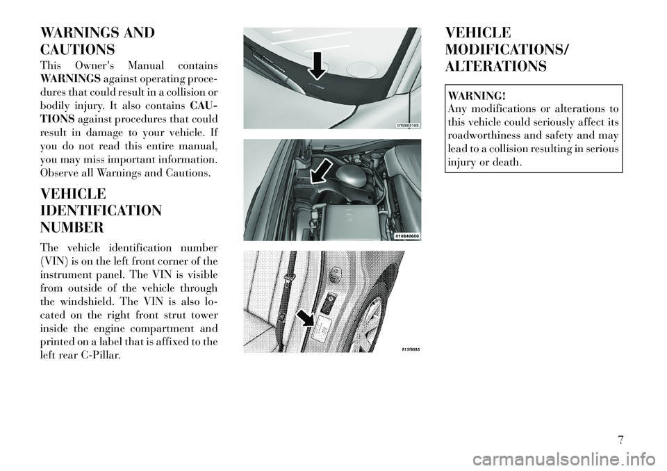
The vehicle identification number
(VIN) is on the left front corner of the
instrument panel. The VIN is visible
from outside of the vehicle through
the windshield. The VIN is also lo-
cated on the right front strut tower
inside the engine compartment and
printed on a label that is affixed to the
left rear C-Pillar. VEHICLE
MODIFICATIONS/
ALTERATIONS
WARNING!
Any modifications or alterations to
this vehicle could seriously affect its
roadworthiness and safety and may
lead to a collision resulting in serious
injury or death.
7
Page 24 of 316
slot and gently pry the two halves of
the RKE transmitter apart. Make sure
not to damage the seal during re-
moval.
3. Remove the battery by turning the
back cover over (battery facing down-
ward) and tapping it lightly on a solid
surface such as a table or similar, then
replace the battery. When replacing
the battery, match the + sign on the
battery to the + sign on the inside of
the battery clip, located on the back
cover. Avoid touching the new battery
with your fingers. Skin oils may cause
battery deterioration. If you touch a
battery, clean it with rubbing alcohol.
4. To assemble the RKE transmitter
case, snap the two halves together.GENERAL INFORMATION
Transmitter and receivers operate on
a carrier frequency of 433.92 MHz as
required by EEC regulations. These
devices must be certified to conform
to specific regulations in each indi-
vidual country. Two sets of regula-
tions are involved: ETS (European
Telecommunication Standard) 300–
220, which most countries use, and
German BZT federal regulation
225Z125, which is based on ETC
300–220 but has additional unique
requirements. Other defined require-
ments are noted in ANNEX VI of
COMMISSION DIRECTIVE 95/56/
EC. Operation is subject to the follow-
ing conditions:
This device may not cause harmful
interference.
This device must accept any inter- ference received, including interfer-
ence that may cause undesired op-
eration.
If your RKE transmitter fails to oper-
ate from a normal distance, check for
these two conditions: 1. A weak battery in the RKE trans-
mitter. The expected life of the battery
is a minimum of three years.
2. Closeness to a radio transmitter
such as a radio station tower, airport
transmitter, and some mobile or CB
radios.
DOOR LOCKS
MANUAL DOOR LOCKS
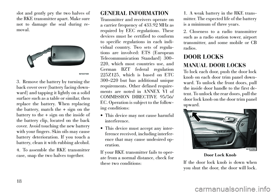
To lock each door, push the door lock
knob on each door trim panel down-
ward. To unlock the front doors, pull
the inside door handle to the first de-
tent. To unlock the rear doors, pull the
door lock knob on the door trim panel
upward.
If the door lock knob is down when
you shut the door, the door will lock.
Door Lock Knob
18
Page 34 of 316

WARNING!(Continued)
A shoulder belt placed behind you
will not protect you from injury
during a collision. You are more
likely to hit your head in a colli-
sion if you do not wear your shoul-
der belt. The lap and shoulder belt
are meant to be used together.
4. Position the lap belt across your
thighs, below your abdomen. To re-
move slack in the lap belt portion, pull
up a bit on the shoulder belt. To
loosen the lap belt if it is too tight, tilt
the latch plate and pull on the lap
belt. A snug belt reduces the risk of
sliding under the belt in a collision.
WARNING!
A lap belt worn too high can in- crease the risk of internal injury in
a collision. The belt forces won't
be at the strong hip and pelvic
bones, but across your abdomen.
Always wear the lap belt as low as
possible and keep it snug.
A twisted belt may not protect you
properly. In a collision, it could
even cut into you. Be sure the belt
is straight. If you can't straighten
a belt in your vehicle, take it to
your authorized dealer immedi-
ately and have it fixed.
5. Position the shoulder belt on your
chest so that it is comfortable and not
resting on your neck. The retractor
will withdraw any slack in the belt.
6. To release the belt, push the red
button on the buckle. The belt will
automatically retract to its stowed po-
sition. If necessary, slide the latch
plate down the webbing to allow the
belt to retract fully.
WARNING!
A frayed or torn belt could rip apart
in a collision and leave you with no
protection. Inspect the belt system
periodically, checking for cuts,
frays, or loose parts. Damaged parts
must be replaced immediately. Do
not disassemble or modify the sys-
tem. Seat belt assemblies must be
replaced after a collision if they have
been damaged (bent retractor, torn
webbing, etc.).
Adjustable Upper Shoulder Belt
Anchorage
In the driver and front passenger
seats, the shoulder belt can be ad-
justed upward or downward to posi-
tion the belt away from your neck.
Push and fully depress the button
above the webbing to release the an-
chorage, then move it up or down to
the position that fits you best.
Removing Slack From Belt
28
Page 35 of 316

As a guide, if you are shorter than
average you will prefer a lower posi-
tion, and if you are taller than average
you will prefer a higher position.
When you release the anchorage try to
move it up and down to make sure
that it is locked in position.
In the rear seat, move toward the cen-
ter of the seat to position the belt away
from your neck.
LAP/SHOULDER BELT
UNTWISTING PROCEDURE
Use the following procedure to un-
twist a twisted lap/shoulder belt.
1. Position the latch plate as close as
possible to the anchor point.2. At about 15 to 30 cm above the
latch plate, grasp and twist the belt
webbing 180 degrees to create a fold
that begins immediately above the
latch plate.
3. Slide the latch plate upward over
the folded webbing. The folded web-
bing must enter the slot at the top of
the latch plate.
4. Continue to slide the latch plate up
until it clears the folded webbing.
SEAT BELTS IN
PASSENGER SEATING
POSITIONS
The seat belts in the rear passenger
seating positions are equipped with
Automatic Locking Retractors (ALR)
which are used to secure a child re-
straint system. For additional infor-
mation, refer to “Installing Child Re-
straints Using The Vehicle Seat Belt”
under the “Child Restraints” section.
The chart below defines the type of
feature for each seating position.
Driver Center Passen-
ger
First
Row N/A N/A N/A
Second Row ALR ALR ALR
N/A — Not Applicable
ALR — Automatic Locking Retrac- tor
If the passenger seating position is
equipped with an ALR and is being
used for normal usage:
Only pull the belt webbing out far
enough to comfortably wrap around
the occupant's mid-section so as to
not activate the ALR. If the ALR is
activated, you will hear a ratcheting
sound as the belt retracts. Allow the
webbing to retract completely in this
case and then carefully pull out only
the amount of webbing necessary to
comfortably wrap around the occu-
pant's mid-section. Slide the latch
plate into the buckle until you hear a
"click."
Adjusting Upper Shoulder Belt
29
Page 39 of 316

versions/markets, where provided). It
is recommended that pets be re-
strained in the rear seat in pet har-
nesses or pet carriers that are secured
by seat belts, and cargo is properly
stowed.
BeltAlert® can be enabled or disabled
by your authorized dealer. LANCIA
does not recommend deactivating
BeltAlert®.
NOTE:
Although BeltAlert® has been de-
activated, the Seat Belt Reminder
Light will continue to illuminate
while the driver’s or front passen-
ger (for versions/markets, where
provided with BeltAlert®) seat belt
remains unfastened.
SEAT BELTS AND
PREGNANT WOMEN
We recommend that pregnant women
use the seat belts throughout their
pregnancy. Keeping the mother safe is
the best way to keep the baby safe.Pregnant women should wear the lap
part of the belt across the thighs and
as snug across the hips as possible.
Keep the belt low so that it does not
come across the abdomen. That way
the strong bones of the hips will take
the force if there is a collision.
SUPPLEMENTAL
RESTRAINT SYSTEM (SRS)
— AIR BAGS
This vehicle has Advanced Front Air
Bags for both the driver and front
passenger as a supplement to the seat
belt restraint systems. The driver's
Advanced Front Air Bag is mounted
in the center of the steering wheel.
The passenger's Advanced Front Air
Bag is mounted in the instrument
panel, above the glove compartment.
The words SRS AIRBAG are em-
bossed on the air bag covers. In addi-
tion, the vehicle is equipped with a
Supplemental Driver Side Knee Air
Bag mounted in the instrument panel
below the steering column.
NOTE:
The Driver and Front Passenger
Advanced Front Air Bags are certi-
fied to regulations for Advanced
Air Bags.
The Advanced Front Air Bags have a
multistage inflator design. This allows
the air bag to have different rates of
inflation based on several factors, in-
cluding the severity and type of colli-
sion.
Advanced Front Air Bag And Knee
Bolster Locations1 — Driver And
Passenger Ad-
vanced Front Air
Bags 2 — Knee Bolster
3 — Supplemental Driver Side Knee
Air Bag (for versions/markets, where
provided)
33
Page 54 of 316

removing slack in the straps accord-
ing to the child restraint manufactur-
er's instructions.
For center seating position route the
tether strap over the seatback and
adjustable headrest (with the head-
rest in the full down position) then
attach the hook to the tether anchor
located in the panel between the rear
seatback and the rear window.
WARNING!
An incorrectly anchored tether strap
could lead to increased head motion
and possible injury to the child. Use
only the anchor positions directly
behind the child seat to secure a
child restraint top tether strap.
NOTE:
Ensure that the tether strap does not slip into the opening be-
tween the seatbacks as you re-
move slack in the strap.
When using the ISOFIX attach- ing system to install a child re-
straint, please ensure that all
seat belts not being used for oc-
cupant restraints are stowed and
out of reach of children. It is recommended that before in-
stalling the child restraint,
buckle the seat belt so the seat
belt is tucked behind the child
restraint and out of reach. If the
buckled seat belt interferes with
the child restraint installation,
instead of tucking the seat belt
behind the child restraint, route
the seat belt through the child
restraint belt path and then
buckle it. This should stow the
seat belt out of the reach of an
inquisitive child. Remind all
children in the vehicle that the
seat belts are not toys and
should not be played with, and
never leave your child unat-
tended in the vehicle.
WARNING!
Improper installation of a child re-
straint to the ISOFIX anchorages
can lead to failure of an infant or
child restraint. The child could be
badly injured or killed. Follow the
manufacturer's directions exactly
when installing an infant or child
restraint.
Adjustable Headrest Release Push
Button
Adjustable Headrest DownwardPosition
48
Page 72 of 316
BLIND SPOT
MONITORING (for
versions/markets, where
provided)
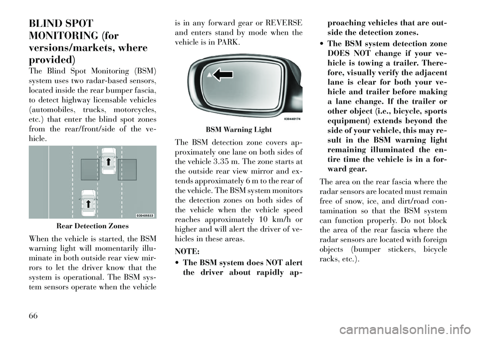
The Blind Spot Monitoring (BSM)
system uses two radar-based sensors,
located inside the rear bumper fascia,
to detect highway licensable vehicles
(automobiles, trucks, motorcycles,
etc.) that enter the blind spot zones
from the rear/front/side of the ve-
hicle.
When the vehicle is started, the BSM
warning light will momentarily illu-
minate in both outside rear view mir-
rors to let the driver know that the
system is operational. The BSM sys-
tem sensors operate when the vehicleis in any forward gear or REVERSE
and enters stand by mode when the
vehicle is in PARK.
The BSM detection zone covers ap-
proximately one lane on both sides of
the vehicle 3.35 m. The zone starts at
the outside rear view mirror and ex-
tends approximately 6 m to the rear of
the vehicle. The BSM system monitors
the detection zones on both sides of
the vehicle when the vehicle speed
reaches approximately 10 km/h or
higher and will alert the driver of ve-
hicles in these areas.
NOTE:
The BSM system does NOT alert
the driver about rapidly ap- proaching vehicles that are out-
side the detection zones.
The BSM system detection zone DOES NOT change if your ve-
hicle is towing a trailer. There-
fore, visually verify the adjacent
lane is clear for both your ve-
hicle and trailer before making
a lane change. If the trailer or
other object (i.e., bicycle, sports
equipment) extends beyond the
side of your vehicle, this may re-
sult in the BSM warning light
remaining illuminated the en-
tire time the vehicle is in a for-
ward gear.
The area on the rear fascia where the
radar sensors are located must remain
free of snow, ice, and dirt/road con-
tamination so that the BSM system
can function properly. Do not block
the area of the rear fascia where the
radar sensors are located with foreign
objects (bumper stickers, bicycle
racks, etc.).
Rear Detection Zones
BSM Warning Light
66
Page 74 of 316
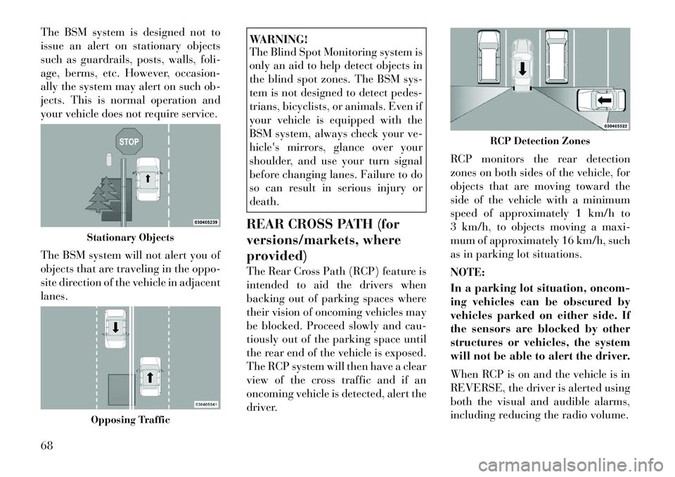
The BSM system is designed not to
issue an alert on stationary objects
such as guardrails, posts, walls, foli-
age, berms, etc. However, occasion-
ally the system may alert on such ob-
jects. This is normal operation and
your vehicle does not require service.
The BSM system will not alert you of
objects that are traveling in the oppo-
site direction of the vehicle in adjacent
lanes.
WARNING!
The Blind Spot Monitoring system is
only an aid to help detect objects in
the blind spot zones. The BSM sys-
tem is not designed to detect pedes-
trians, bicyclists, or animals. Even if
your vehicle is equipped with the
BSM system, always check your ve-
hicle's mirrors, glance over your
shoulder, and use your turn signal
before changing lanes. Failure to do
so can result in serious injury or
death.
REAR CROSS PATH (for
versions/markets, where
provided)
The Rear Cross Path (RCP) feature is
intended to aid the drivers when
backing out of parking spaces where
their vision of oncoming vehicles may
be blocked. Proceed slowly and cau-
tiously out of the parking space until
the rear end of the vehicle is exposed.
The RCP system will then have a clear
view of the cross traffic and if an
oncoming vehicle is detected, alert the
driver. RCP monitors the rear detection
zones on both sides of the vehicle, for
objects that are moving toward the
side of the vehicle with a minimum
speed of approximately 1 km/h to
3 km/h, to objects moving a maxi-
mum of approximately 16 km/h, such
as in parking lot situations.
NOTE:
In a parking lot situation, oncom-
ing vehicles can be obscured by
vehicles parked on either side. If
the sensors are blocked by other
structures or vehicles, the system
will not be able to alert the driver.
When RCP is on and the vehicle is in
REVERSE, the driver is alerted using
both the visual and audible alarms,
including reducing the radio volume.
Stationary ObjectsOpposing Traffic
RCP Detection Zones
68
Page 77 of 316
WARNING!
Any voice commanded system
should be used only in safe driving
conditions following local laws and
phone use. All attention should be
kept on the roadway ahead. Failure
to do so may result in an accident
causing serious injury or death.
The Uconnect™ Phone is driven
through your Bluetooth® “Hands-
Free Profile” mobile phone.
Uconnect™ features Bluetooth®
technology - the global standard that
enables different electronic devices to
connect to each other without wires or
a docking station, so Uconnect™
Phone works no matter where you
stow your mobile phone (be it your
purse, pocket, or briefcase), as long as
your phone is turned on and has been
paired to the vehicle's Uconnect™
Phone. The Uconnect™ Phone allows
up to ten mobile phones or audio de-
vices to be linked to the system. Only
one linked (or paired) mobile phone
and one audio device can be used with the system at a time. The system is
available in English, Spanish, or
French languages.
Uconnect™ Phone Button
The Uconnect™ Phone
Button is used to get into
the phone mode and make
calls, show recent, incom-
ing, outgoing calls, view phonebook
etc., When you press the button you
will hear a BEEP. The beep is your
signal to give a command.
Uconnect™ Voice Command Button The Uconnect™ Voice
Command
Button is
only used for “barge in”
and when you are already in
a call and you want to send Tones or
make another call.
The
button is also used to access
the Voice Commands for the
Uconnect™ Voice Command features
if your vehicle is equipped. Please see
the Uconnect™ Voice Command sec-
tion for direction on how to use the
button.
The Uconnect™ Phone is fully inte-
grated with the vehicle's audio sys- tem. The volume of the Uconnect™
Phone can be adjusted either from the
radio volume control knob or from the
steering wheel radio control (right
switch), if so equipped.
OPERATION
Voice commands can be used to oper-
ate the Uconnect™ Phone and to
navigate through the Uconnect™
Phone menu structure. Voice com-
mands are required after most
Uconnect™ Phone prompts. There
are two general methods for how
Voice Command works:
1. Say compound commands like
“Call John Smith mobile”.
2. Say the individual commands and
allow the system to guide you to com-
plete the task.
You will be prompted for a specific
command and then guided through
the available options.
Prior to giving a voice command,
one must wait for the beep, which
follows the “Listen” prompt or an-
other prompt.
71
Page 83 of 316
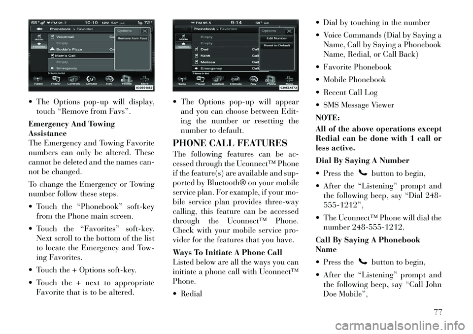
The Options pop-up will display,touch “Remove from Favs”.
Emergency And Towing
Assistance
The Emergency and Towing Favorite
numbers can only be altered. These
cannot be deleted and the names can-
not be changed.
To change the Emergency or Towing
number follow these steps.
Touch the “Phonebook” soft-key from the Phone main screen.
Touch the “Favorites” soft-key. Next scroll to the bottom of the list
to locate the Emergency and Tow-
ing Favorites.
Touch the + Options soft-key.
Touch the + next to appropriate Favorite that is to be altered. The Options pop-up will appear
and you can choose between Edit-
ing the number or resetting the
number to default.
PHONE CALL FEATURES
The following features can be ac-
cessed through the Uconnect™ Phone
if the feature(s) are available and sup-
ported by Bluetooth® on your mobile
service plan. For example, if your mo-
bile service plan provides three-way
calling, this feature can be accessed
through the Uconnect™ Phone.
Check with your mobile service pro-
vider for the features that you have.
Ways To Initiate A Phone Call
Listed below are all the ways you can
initiate a phone call with Uconnect™
Phone.
Redial Dial by touching in the number
Voice Commands (Dial by Saying a
Name, Call by Saying a Phonebook
Name, Redial, or Call Back)
Favorite Phonebook
Mobile Phonebook
Recent Call Log
SMS Message Viewer
NOTE:
All of the above operations except
Redial can be done with 1 call or
less active.
Dial By Saying A Number
Press the
button to begin,
After the “Listening” prompt and the following beep, say “Dial 248-
555-1212”,
The Uconnect™ Phone will dial the number 248-555-1212.
Call By Saying A Phonebook
Name
Press thebutton to begin,
After the “Listening” prompt and the following beep, say “Call John
Doe Mobile”,
77