clock Lancia Thema 2012 Owner handbook (in English)
[x] Cancel search | Manufacturer: LANCIA, Model Year: 2012, Model line: Thema, Model: Lancia Thema 2012Pages: 316, PDF Size: 3.85 MB
Page 111 of 316
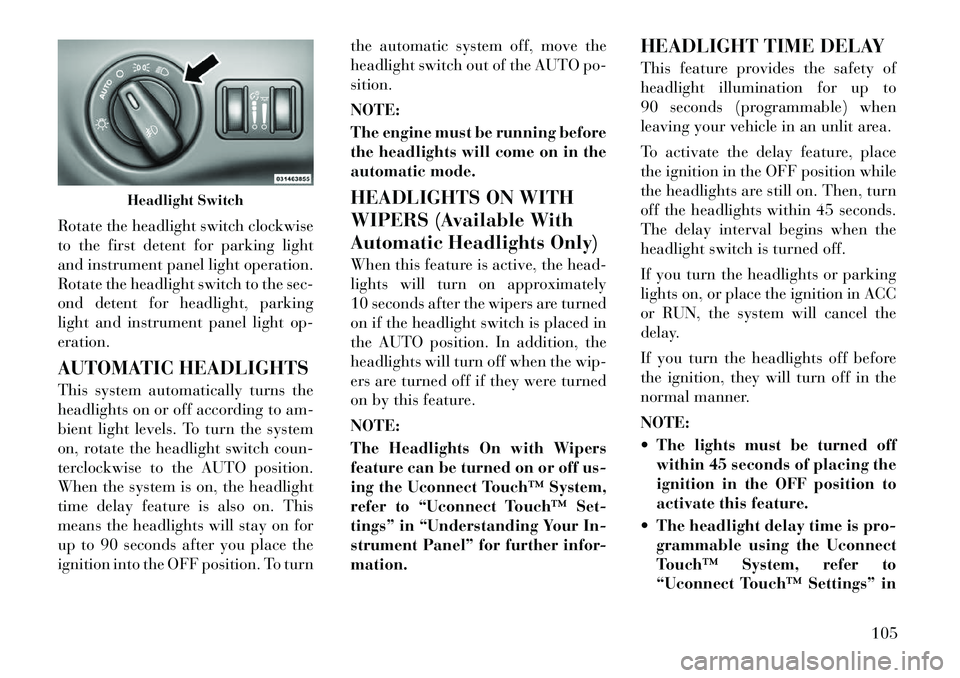
Rotate the headlight switch clockwise
to the first detent for parking light
and instrument panel light operation.
Rotate the headlight switch to the sec-
ond detent for headlight, parking
light and instrument panel light op-
eration.
AUTOMATIC HEADLIGHTS
This system automatically turns the
headlights on or off according to am-
bient light levels. To turn the system
on, rotate the headlight switch coun-
terclockwise to the AUTO position.
When the system is on, the headlight
time delay feature is also on. This
means the headlights will stay on for
up to 90 seconds after you place the
ignition into the OFF position. To turnthe automatic system off, move the
headlight switch out of the AUTO po-
sition.
NOTE:
The engine must be running before
the headlights will come on in the
automatic mode.
HEADLIGHTS ON WITH
WIPERS (Available With
Automatic Headlights Only)
When this feature is active, the head-
lights will turn on approximately
10 seconds after the wipers are turned
on if the headlight switch is placed in
the AUTO position. In addition, the
headlights will turn off when the wip-
ers are turned off if they were turned
on by this feature.
NOTE:
The Headlights On with Wipers
feature can be turned on or off us-
ing the Uconnect Touch™ System,
refer to “Uconnect Touch™ Set-
tings” in “Understanding Your In-
strument Panel” for further infor-
mation.
HEADLIGHT TIME DELAY
This feature provides the safety of
headlight illumination for up to
90 seconds (programmable) when
leaving your vehicle in an unlit area.
To activate the delay feature, place
the ignition in the OFF position while
the headlights are still on. Then, turn
off the headlights within 45 seconds.
The delay interval begins when the
headlight switch is turned off.
If you turn the headlights or parking
lights on, or place the ignition in ACC
or RUN, the system will cancel the
delay.
If you turn the headlights off before
the ignition, they will turn off in the
normal manner.
NOTE:
The lights must be turned off
within 45 seconds of placing the
ignition in the OFF position to
activate this feature.
The headlight delay time is pro- grammable using the Uconnect
Touch™ System, refer to
“Uconnect Touch™ Settings” in
Headlight Switch
105
Page 156 of 316
MESSAGES # . . . . . . . . . . . . . . . . . . . . . . . . . 167
TURN MENU OFF . . . . . . . . . . . . . . . . . . . . . 167
Uconnect Touch™ SETTINGS . . . . . . . . . . . . . . 167 HARD-KEYS . . . . . . . . . . . . . . . . . . . . . . . . . 167
SOFT-KEYS . . . . . . . . . . . . . . . . . . . . . . . . . . 167
CUSTOMER PROGRAMMABLE FEATURES— Uconnect Touch™ SYSTEM 8.4
SETTINGS . . . . . . . . . . . . . . . . . . . . . . . . . . . 168
SOUND SYSTEMS . . . . . . . . . . . . . . . . . . . . . . . 177
NAVIGATION SYSTEM (for versions/markets, where provided) . . . . . . . . . . . . . . . . . . . . . . . . . 177
SETTING THE ANALOG CLOCK . . . . . . . . . . . . 178
iPod®/USB/MP3 CONTROL (for vehicles/ markets, where provided) . . . . . . . . . . . . . . . . . 178
HARMAN KARDON® Logic7® HIGH PERFORMANCE MULTICHANNEL
SURROUND SOUND SYSTEM WITH
DRIVER-SELECTABLE SURROUND (DSS) (for
versions/markets, where required) . . . . . . . . . . . 178
STEERING WHEEL AUDIO CONTROLS . . . . . . 179 Radio Operation . . . . . . . . . . . . . . . . . . . . . . 179
CD Player . . . . . . . . . . . . . . . . . . . . . . . . . . . 179
CD/DVD DISC MAINTENANCE . . . . . . . . . . . . . 179
RADIO OPERATION AND MOBILE PHONES . . . 180
CLIMATE CONTROLS . . . . . . . . . . . . . . . . . . . . 180 GENERAL OVERVIEW . . . . . . . . . . . . . . . . . 180
150
Page 158 of 316
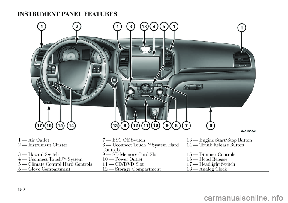
INSTRUMENT PANEL FEATURES1 — Air Outlet7 — ESC Off Switch13 — Engine Start/Stop Button
2 — Instrument Cluster 8 — Uconnect Touch™ System Hard
Controls 14 — Trunk Release Button
3 — Hazard Switch 9 — SD Memory Card Slot15 — Dimmer Controls
4 — Uconnect Touch™ System 10 — Power Outlet 16 — Hood Release
5 — Climate Control Hard Controls 11 — CD/DVD Slot 17 — Headlight Switch
6 — Glove Compartment 12 — Storage Compartment18 — Analog Clock
152
Page 174 of 316
CUSTOMER
PROGRAMMABLE
FEATURES — Uconnect
Touch™ SYSTEM 8.4
SETTINGS
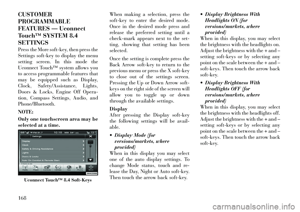
Press the More soft-key, then press the
Settings soft-key to display the menu
setting screen. In this mode the
Uconnect Touch™ system allows you
to access programmable features that
may be equipped such as Display,
Clock, Safety/Assistance, Lights,
Doors & Locks, Engine Off Opera-
tion, Compass Settings, Audio, and
Phone/Bluetooth.
NOTE:
Only one touchscreen area may be
selected at a time.When making a selection, press the
soft-key to enter the desired mode.
Once in the desired mode press and
release the preferred setting until a
check-mark appears next to the set-
ting, showing that setting has been
selected.
Once the setting is complete press the
Back Arrow soft-key to return to the
previous menu or press the X soft-key
to close out of the settings screen.
Pressing the Up or Down Arrow soft-
keys on the right side of the screen will
allow you to toggle up or down
through the available settings.
Display
After pressing the Display soft-key
the following settings will be avail-
able.
Display Mode (for
versions/markets, where
provided)
When in this display you may select
one of the auto display settings. To
change Mode status, touch and re-
lease the Day, Night or Auto soft-key.
Then touch the arrow back soft-key. Display Brightness With
Headlights ON (for
versions/markets, where
provided)
When in this display, you may select
the brightness with the headlights on.
Adjust the brightness with the + and –
setting soft-keys or by selecting any
point on the scale between the + and –
soft-keys. Then touch the arrow back
soft-key.
Display Brightness With Headlights OFF (for
versions/markets, where
provided)
When in this display, you may select
the brightness with the headlights off.
Adjust the brightness with the + and –
setting soft-keys or by selecting any
point on the scale between the + and –
soft-keys. Then touch the arrow back
soft-key.
Uconnect Touch™ 8.4 Soft-Keys
168
Page 176 of 316
Clock
After pressing the Clock soft-key the
following settings will be available.
Sync Time With GPS (forversions/markets, where
provided)
When in this display, you may auto-
matically have the radio set the time.
To change the Sync Time setting
touch the Sync with GPS Time soft-
key until a check-mark appears next
to the setting, showing that setting has
been selected. Touch the back arrow
soft-key to return to the previous
menu.
Set Time Hours (for versions/markets, where
provided)
When in this display, you may adjust
the hours. The Sync with GPS Time
soft-key must be unchecked. To make
your selection touch the + or - soft-
keys to adjust the hours up or down.
Touch the back arrow soft-key to re-
turn to the previous menu or touch the
X soft-key to close out of the settings
screen. Set Time Minutes (for
versions/markets, where
provided)
When in this display, you may adjust
the minutes. The Sync with GPS Time
soft-key must be unchecked. To make
your selection touch the + or - soft-
keys to adjust the minutes up or
down. Touch the back arrow soft-key
to return to the previous menu or
touch the X soft-key to close out of the
settings screen.
Time Format (for versions/ markets, where provided)
When in this display, you may select
the time format display setting. Touch
the Time Format soft-key until a
check-mark appears next to the 12hrs
or 24hrs setting, showing that setting
has been selected. Touch the back ar-
row soft-key to return to the previous
menu. Show Time In Status Bar (for
versions/markets, where
provided)
When in this display, you may turn on
or shut off the digital clock in the
status bar. To change the Show Time
Status setting touch the Show Time in
Status Bar soft-key until a check-
mark appears next to setting, showing
that setting has been selected. Touch
the back arrow soft-key to return to
the previous menu.
Safety / Assistance
After pressing the Safety / Assistance
soft-key the following settings will be
available.
Front Collision Sensitivity (for versions/markets, where
provided)
The Front Collision Warning (FCW)
feature can be can be set to Far, set to
Near or turned Off. The default status
of FCW is the Far setting. This means
the system will warn you of a possible
collision with the vehicle in front of
you when you are farther away. This
gives you the most reaction time. To
change the setting for more dynamic
driving, select the Near setting. This
170
Page 184 of 316
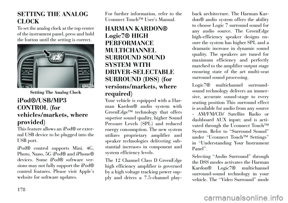
SETTING THE ANALOG
CLOCKTo set the analog clock at the top center
of the instrument panel, press and hold
the button until the setting is correct.iPod®/USB/MP3
CONTROL (for
vehicles/markets, where
provided)
This feature allows an iPod® or exter-
nal USB device to be plugged into the
USB port.
iPod® control supports Mini, 4G,
Photo, Nano, 5G iPod® and iPhone®
devices. Some iPod® software ver-
sions may not fully support the iPod®
control features. Please visit Apple’s
website for software updates.For further information, refer to the
Uconnect Touch™ User’s Manual.
HARMAN KARDON®
Logic7® HIGH
PERFORMANCE
MULTICHANNEL
SURROUND SOUND
SYSTEM WITH
DRIVER-SELECTABLE
SURROUND (DSS) (for
versions/markets, where
required)
Your vehicle is equipped with a Har-
man Kardon® audio system with
GreenEdge™ technology that offers
superior sound quality, higher Sound
Pressure Levels (SPL) and reduced
energy consumption. The new system
utilizes proprietary amplifier and
speaker technologies delivering sub-
stantial increases in component and
system efficiency levels.
The 12 Channel Class D GreenEdge
high efficiency amplifier is governed
by a high voltage tracking power sup-
ply and drives a 7.5-channel play-back architecture. The Harman Kar-
don® audio system offers the ability
to choose Logic 7 surround sound for
any audio source. The GreenEdge
high-efficiency speaker designs en-
sure the system has higher SPL and a
dramatic increase in dynamic sound
quality. The speakers are tuned for
maximum efficiency and perfectly
matched to the amplifier output stage
ensuring state of the art multi-seat
surround sound processing.
Logic7® multichannel surround-
sound technology delivers an immer-
sive, accurate sound-stage to every
seating position This surround effect
is available for audio from any source
- AM/FM/CD/ Satellite Radio or
dashboard AUX input; and is acti-
vated through the Uconnect Touch™
System. Refer to “Surround Sound”
under “Uconnect Touch™ Settings”
in “Understanding Your Instrument
Panel”.
Selecting “Audio Surround” through
the DSS modes activates the Harman
Kardon® Logic7® multichannel
surround-sound technology in your
vehicle. The “Video Surround” mode
Setting The Analog Clock
178
Page 185 of 316
is described under Driver-Selectable
Surround (DSS). The Video Surround
Mode will only be available for video
media sources (DVDs, Video CDs, or
other video media supported by the
radio). Some audio will sound better
in DSS modes, others in Stereo mode.
When in “Audio Surround” mode,
balance is set automatically. Fader
control is available in surround mode
but should be set to the center position
for optimal surround performance.
STEERING WHEEL
AUDIO CONTROLS
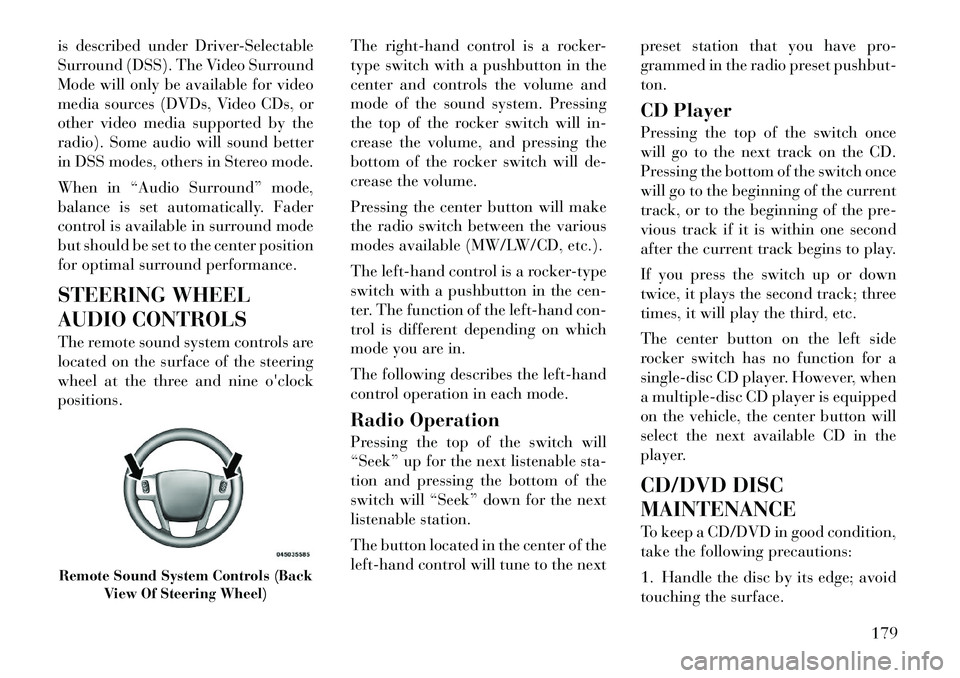
The remote sound system controls are
located on the surface of the steering
wheel at the three and nineo'clock
positions. The
right-hand control is a rocker-
type switch with a pushbutton in the
center and controls the volume and
mode of the sound system. Pressing
the top of the rocker switch will in-
crease the volume, and pressing the
bottom of the rocker switch will de-
crease the volume.
Pressing the center button will make
the radio switch between the various
modes available (MW/LW/CD, etc.).
The left-hand control is a rocker-type
switch with a pushbutton in the cen-
ter. The function of the left-hand con-
trol is different depending on which
mode you are in.
The following describes the left-hand
control operation in each mode.
Radio Operation
Pressing the top of the switch will
“Seek” up for the next listenable sta-
tion and pressing the bottom of the
switch will “Seek” down for the next
listenable station.
The button located in the center of the
left-hand control will tune to the next preset station that you have pro-
grammed in the radio preset pushbut-
ton.
CD Player
Pressing the top of the switch once
will go to the next track on the CD.
Pressing the bottom of the switch once
will go to the beginning of the current
track, or to the beginning of the pre-
vious track if it is within one second
after the current track begins to play.
If you press the switch up or down
twice, it plays the second track; three
times, it will play the third, etc.
The center button on the left side
rocker switch has no function for a
single-disc CD player. However, when
a multiple-disc CD player is equipped
on the vehicle, the center button will
select the next available CD in the
player.
CD/DVD DISC
MAINTENANCE
To keep a CD/DVD in good condition,
take the following precautions:
1. Handle the disc by its edge; avoid
touching the surface.Remote Sound System Controls (Back
View Of Steering Wheel)
179
Page 187 of 316
Button Descriptions (Applies To
Both Hard-keys And Soft-keys)
1. A/C Button
Press and release to change the cur-
rent Air Conditioning (A/C) setting,
the indicator illuminates when A/C is
ON. Performing this function will
cause the automatic operation to
switch into manual mode and the
AUTO indicator will turn off.
2. Recirculation Button
Press and release to change the cur-
rent setting, the indicator illuminates
when ON.
3. Blower Control
Blower control is used to regulate the
amount of air forced through the cli-
mate system. There are seven blower
speeds available. Adjusting the
blower will cause automatic mode to
switch to manual operation. The
speeds can be selected using either
hard-keys or soft-keys as follows:Hard-key
The blower speed increases as you
turn the control clockwise from the
lowest blower setting. The blower
speed decreases as you turn the knob
counter-clockwise.
Soft-key — Uconnect Touch™
System 8.4
Use the small blower icon to reduce
the blower setting and the large
blower icon to increase the blower
setting. Blower can also be selected by
pressing the blower bar area between
the icons.
4. Front Defrost Button
Press and release to change the cur-
rent airflow setting to Defrost mode.
The indicator illuminates when this
feature is ON. Performing this func-
tion will cause the ATC to switch into
manual mode. The blower speed may
increase when Defrost mode is se-
lected. If the front defrost mode is
turned off the climate system will re-
turn the previous setting.5. Rear Defrost Button
Press and release this button to turn
on the rear window defroster and the
heated outside mirrors (for versions/
markets, where provided). An indica-
tor will illuminate when the rear win-
dow defroster is on. The rear window
defroster automatically turns off after
10 minutes.
CAUTION!
Failure to follow these cautions can
cause damage to the heating ele-
ments:
Use care when washing the inside
of the rear window. Do not use
abrasive window cleaners on the
interior surface of the window.
Use a soft cloth and a mild wash-
ing solution, wiping parallel to the
heating elements. Labels can be
peeled off after soaking with
warm water.
Do not use scrapers, sharp instru-
ments, or abrasive window clean-
ers on the interior surface of the
window.
Keep all objects a safe distance
from the window.
181
Page 284 of 316
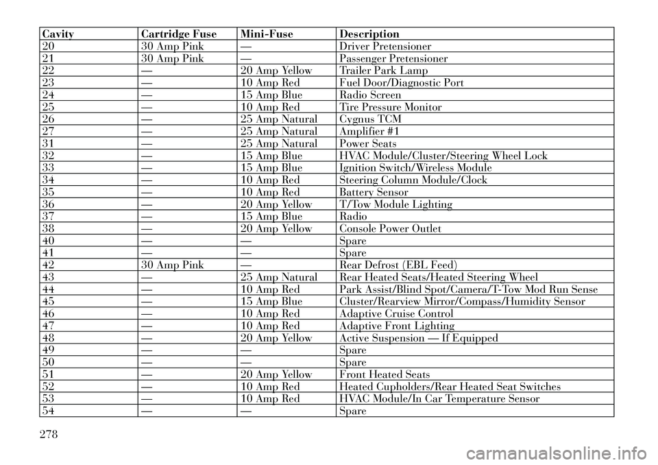
CavityCartridge Fuse Mini-Fuse Description
20 30 Amp Pink — Driver Pretensioner
21 30 Amp Pink — Passenger Pretensioner
22 —20 Amp Yellow Trailer Park Lamp
23 —10 Amp Red Fuel Door/Diagnostic Port
24 —15 Amp Blue Radio Screen
25 —10 Amp Red Tire Pressure Monitor
26 —25 Amp Natural Cygnus TCM
27 —25 Amp Natural Amplifier #1
31 —25 Amp Natural Power Seats
32 —15 Amp Blue HVAC Module/Cluster/Steering Wheel Lock
33 —15 Amp Blue Ignition Switch/Wireless Module
34 —10 Amp Red Steering Column Module/Clock
35 —10 Amp Red Battery Sensor
36 —20 Amp Yellow T/Tow Module Lighting
37 —15 Amp Blue Radio
38 —20 Amp Yellow Console Power Outlet
40 ——Spare
41 ——Spare
42 30 Amp Pink — Rear Defrost (EBL Feed)
43 —25 Amp Natural Rear Heated Seats/Heated Steering Wheel
44 —10 Amp Red Park Assist/Blind Spot/Camera/T-Tow Mod Run Sense
45 —15 Amp Blue Cluster/Rearview Mirror/Compass/Humidity Sensor
46 —10 Amp Red Adaptive Cruise Control
47 —10 Amp Red Adaptive Front Lighting
48 —20 Amp Yellow Active Suspension — If Equipped
49 ——Spare
50 ——Spare
51 —20 Amp Yellow Front Heated Seats
52 —10 Amp Red Heated Cupholders/Rear Heated Seat Switches
53 —10 Amp Red HVAC Module/In Car Temperature Sensor
54 ——Spare
278
Page 288 of 316
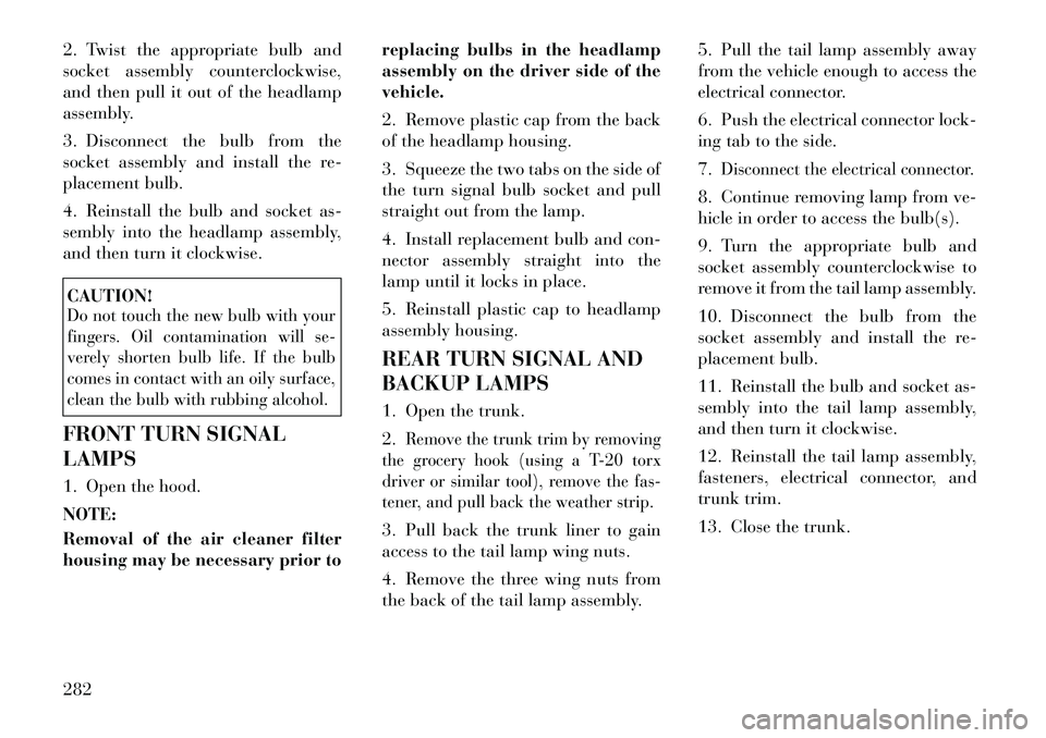
2. Twist the appropriate bulb and
socket assembly counterclockwise,
and then pull it out of the headlamp
assembly.
3. Disconnect the bulb from the
socket assembly and install the re-
placement bulb.
4. Reinstall the bulb and socket as-
sembly into the headlamp assembly,
and then turn it clockwise.CAUTION!Do not touch the new bulb with your
fingers. Oil contamination will se-
verely shorten bulb life. If the bulb
comes in contact with an oily surface,
clean the bulb with rubbing alcohol.FRONT TURN SIGNAL
LAMPS
1. Open the hood.
NOTE:
Removal of the air cleaner filter
housing may be necessary prior toreplacing bulbs in the headlamp
assembly on the driver side of the
vehicle.
2. Remove plastic cap from the back
of the headlamp housing.
3. Squeeze the two tabs on the side of
the turn signal bulb socket and pull
straight out from the lamp.
4. Install replacement bulb and con-
nector assembly straight into the
lamp until it locks in place.
5. Reinstall plastic cap to headlamp
assembly housing.
REAR TURN SIGNAL AND
BACKUP LAMPS
1. Open the trunk.
2.
Remove the trunk trim by removing
the grocery hook (using a T-20 torx
driver or similar tool), remove the fas-
tener, and pull back the weather strip.
3. Pull back the trunk liner to gain
access to the tail lamp wing nuts.
4. Remove the three wing nuts from
the back of the tail lamp assembly. 5. Pull the tail lamp assembly away
from the vehicle enough to access the
electrical connector.
6. Push the electrical connector lock-
ing tab to the side.
7.
Disconnect the electrical connector.
8. Continue removing lamp from ve-
hicle in order to access the bulb(s).
9. Turn the appropriate bulb and
socket assembly counterclockwise to
remove it from the tail lamp assembly.
10. Disconnect the bulb from the
socket assembly and install the re-
placement bulb.
11. Reinstall the bulb and socket as-
sembly into the tail lamp assembly,
and then turn it clockwise.
12. Reinstall the tail lamp assembly,
fasteners, electrical connector, and
trunk trim.
13. Close the trunk.
282