instrument cluster Lancia Thema 2012 Owner handbook (in English)
[x] Cancel search | Manufacturer: LANCIA, Model Year: 2012, Model line: Thema, Model: Lancia Thema 2012Pages: 316, PDF Size: 3.85 MB
Page 19 of 316
IGNITION OR ACCESSORY
ON MESSAGE
Opening the driver's door when the
ignition is in ACC or ON (engine not
running), a chime will sound to re-
mind you to cycle the ignition to OFF.
In addition to the chime, the ignition
or accessory on message will display
in the cluster.
NOTE:
With the Uconnect Touch™ sys-
tem, the power window switches,
radio, power sunroof (for versions/
markets, where provided), and
power outlets will remain active
for up to 10 minutes after the igni-
tion is cycled to the OFF position.
Opening either front door will can-
cel this feature. The time for this
feature is programmable. Refer to
“Uconnect Touch™ Settings” in
“Understanding Your Instrument
Panel” for further information.
WARNING!
When leaving the vehicle, alwaysremove the key fob and lock your
vehicle.
Never leave children alone in a
vehicle, or with access to an un-
locked vehicle.
Allowing children to be in a ve-
hicle unattended is dangerous for
a number of reasons. A child or
others could be seriously or fatally
injured. Children should be
warned not to touch the parking
brake, brake pedal or the shift
lever.
Do not leave the key fob in or near
the vehicle, and do not leave Key-
less Enter-N-Go in the ACC or
ON/RUN mode. A child could op-
erate power windows, other con-
trols, or move the vehicle.
Do not leave children or animals
inside parked vehicles in hot
weather. Interior heat build-up
may cause serious injury or death.
CAUTION!
An unlocked car is an invitation to
thieves. Always remove the Key Fob
from vehicle, cycle the ignition OFF
and lock all doors when leaving the
vehicle unattended.
SENTRY KEY®
The Sentry Key® Immobilizer System
prevents unauthorized vehicle opera-
tion by disabling the engine. The sys-
tem does not need to be armed or
activated. Operation is automatic, re-
gardless of whether the vehicle is
locked or unlocked.
The system uses a Key Fob with Re-
mote Keyless Entry (RKE) transmit-
ter, a Keyless Ignition Node (KIN) and
a RF receiver to prevent unauthorized
vehicle operation. Therefore, only
Key Fobs that are programmed to the
vehicle can be used to start and oper-
ate the vehicle.
After placing the ignition in the ON/
RUN position, the Vehicle Security
Light will turn on for three seconds
for a bulb check. If the light remains
on after the bulb check, it indicates
13
Page 31 of 316
With the ignition in the ON/RUN po-
sition, the Trunk Open symbol will
display in the instrument cluster indi-
cating that the trunk is open. The
odometer display will reappear once
the trunk is closed.
With the ignition in the OFF position,
the Trunk Open symbol will display
until the trunk is closed.
Refer to “Keyless Enter-N-Go” in
“Things To Know Before Starting
Your Vehicle” for more information
on trunk operation with the Passive
Entry feature.
TRUNK SAFETY
WARNINGWARNING!Do not allow children to have access to
the trunk, either by climbing into the
trunk from outside, or through the
inside of the vehicle. Always close the
trunk lid when your vehicle is unat-
tended. Once in the trunk, young chil-
dren may not be able to escape, even if
they entered through the rear seat. If
trapped in the trunk, children can die
from suffocation or heat stroke.
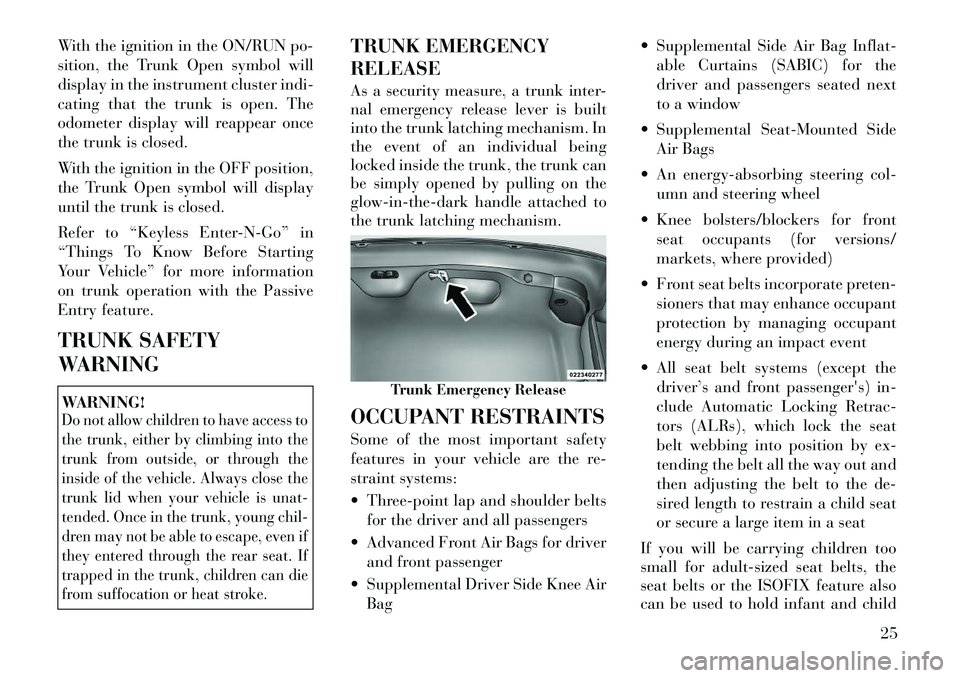
TRUNK EMERGENCY
RELEASE
As a security measure, a trunk inter-
nal emergency release lever is built
into the trunk latching mechanism. In
the event of an individual being
locked inside the trunk, the trunk can
be simply opened by pulling on the
glow-in-the-dark handle attached to
the trunk latching mechanism.
OCCUPANT RESTRAINTS
Some of the most important safety
features in your vehicle are the re-
straint systems:
Three-point lap and shoulder beltsfor the driver and all passengers
Advanced Front Air Bags for driver and front passenger
Supplemental Driver Side Knee Air Bag Supplemental Side Air Bag Inflat-
able Curtains (SABIC) for the
driver and passengers seated next
to a window
Supplemental Seat-Mounted Side Air Bags
An energy-absorbing steering col- umn and steering wheel
Knee bolsters/blockers for front seat occupants (for versions/
markets, where provided)
Front seat belts incorporate preten- sioners that may enhance occupant
protection by managing occupant
energy during an impact event
All seat belt systems (except the driver’s and front passenger's) in-
clude Automatic Locking Retrac-
tors (ALRs), which lock the seat
belt webbing into position by ex-
tending the belt all the way out and
then adjusting the belt to the de-
sired length to restrain a child seat
or secure a large item in a seat
If you will be carrying children too
small for adult-sized seat belts, the
seat belts or the ISOFIX feature also
can be used to hold infant and child
Trunk Emergency Release
25
Page 44 of 316
ACC position, or not in the ignition,
the air bag system is not on and the air
bags will not inflate.
The ORC contains a backup power
supply system that may deploy the air
bags even if the battery loses power or
it becomes disconnected prior to de-
ployment.Also, the ORC turns on the
Air Bag Warning Light in
the instrument panel for
approximately four to eight
seconds for a self-check when the ig-
nition is first turned on. After the self-
check, the Air Bag Warning Light will
turn off. If the ORC detects a mal-
function in any part of the system, it
turns on the Air Bag Warning Light,
either momentarily or continuously. A
single chime will sound if the light
comes on again after initial startup.
It also includes diagnostics that will
illuminate the instrument cluster Air
Bag Warning Light if a malfunction is
noted that could affect the air bag
system. The diagnostics also record
the nature of the malfunction.
WARNING!
Ignoring the Air Bag Warning Light
in your instrument panel could
mean you won't have the air bags to
protect you in a collision. If the light
does not come on as a bulb check
when the ignition is first turned on,
stays on after you start the vehicle,
or if it comes on as you drive, have
an authorized dealer service the air
bag system immediately.
Driver And Passenger Advanced
Front Air Bag Inflator Units
The Driver and Passenger Advanced
Front Air Bag Inflator Units are lo-
cated in the center of the steering
wheel and on the right side of the
instrument panel. When the ORC de-
tects a collision requiring the Ad-
vanced Front Air Bags, it signals the
inflator units. A large quantity of non-
toxic gas is generated to inflate the
Advanced Front Air Bags. Different
air bag inflation rates are possible,
based on the collision type and sever-
ity. The steering wheel hub trim cover
and the upper right side of the instru-
ment panel separate and fold out of the way as the air bags inflate to their
full size. The air bags fully inflate in
about 50 to 70 milliseconds. This is
about half of the time it takes to blink
your eyes. The air bags then quickly
deflate while helping to restrain the
driver and front passenger.
The Advanced Front Air Bag gas is
vented through the vent holes in the
sides of the air bag. In this way, the air
bags do not interfere with your con-
trol of the vehicle.
Supplemental Driver Side Knee
Air Bag Inflator Unit (for
versions/markets, where
provided)
The Supplemental Driver Side Knee
Air Bag unit is located in the instru-
ment panel trim beneath the steering
column. When the ORC detects a col-
lision requiring the air bag, it signals
the inflator units. A large quantity of
non-toxic gas is generated to inflate
the Supplemental Driver Side Knee
Air Bag. The trim cover separates and
folds out of the way allowing the air
bag to inflate to the full size. The air
bag fully inflates in about 15 to 20
milliseconds. The Supplemental
38
Page 108 of 316

the memory save function and the (1)
and (2) buttons which are used to
recall either of two pre-programmed
memory profiles.
PROGRAMMING THE
MEMORY FEATURE
NOTE:
Saving a new memory profile will
erase an existing profile from
memory.
To create a new memory profile, per-
form the following:
1. Cycle the ignition to the RUN po-
sition.
2. Adjust all memory profile settings
to desired preferences (i.e., seat, side
mirror, adjustable pedals [for
versions/markets, where provided],power tilt and telescopic steering col-
umn [for versions/markets, where
provided], and radio station presets).
3. Press and release the SET (S) but-
ton on the memory switch.
4. Within five seconds, press and re-
lease the MEMORY button 1 or 2. The
Electronic Vehicle Information Center
(EVIC) (for versions/markets, where
provided) will display which memory
position has been set.
NOTE:
Memory profiles can be set with-
out the vehicle in PARK, but the
vehicle must be in PARK to re-
call a memory profile.
The Recall Memory with Remote Key Unlock feature can be
turned on and off using the
Uconnect Touch™ System, refer
to “Uconnect Touch™ Settings”
in “Understanding Your Instru-
ment Panel” for further infor-
mation. LINKING AND UNLINKING
THE REMOTE KEYLESS
ENTRY TRANSMITTER TO
MEMORY
Your RKE transmitters can be pro-
grammed to recall one of two pre-
programmed memory profiles by
pressing the UNLOCK button on the
RKE transmitter.
To program your RKE transmitters,
perform the following:
1. Cycle the ignition to the OFF posi-
tion.
2. Select desired memory profile (1)
or (2).
3. Once the profile has been recalled,
press and release the SET (S) button
on the memory switch, then press and
release button (1) or (2) accordingly.
“Memory Profile Set” (1 or 2) will
display in the instrument cluster on
vehicles equipped with the EVIC.
4. Press and release the LOCK button
on the RKE transmitter within 10 sec-
onds.
Memory Seat Switch
102
Page 113 of 316
LIGHTS-ON REMINDER
If the headlights or parking lights are
on after the ignition is placed in the
OFF position, a chime will sound to
alert the driver when the driver's door
is opened.
FOG LIGHTSThe fog light switch is built
into the headlight switch.
To activate the fog lights,
turn the headlamp switch to
the park lamp or headlamp position.
Press the headlight switch once for
front fog lights, press the switch a
second time for front and rear fog
lights. Pressing the switch a third time
will deactivate the rear fog lights, and
a fourth time will deactivate the front
fog lights. Turning the headlight
switch off will also deactivate the fog
lights.
An indicator light in the instrument
cluster illuminates when the fog lights
are turned on.
NOTE:
The front fog lights will activate
automatically when turning on the
position lights or the low beam headlights if previously deacti-
vated by turning the headlight
switch off. The rear fog lights will
only turn on by operating the
switch as previously described.
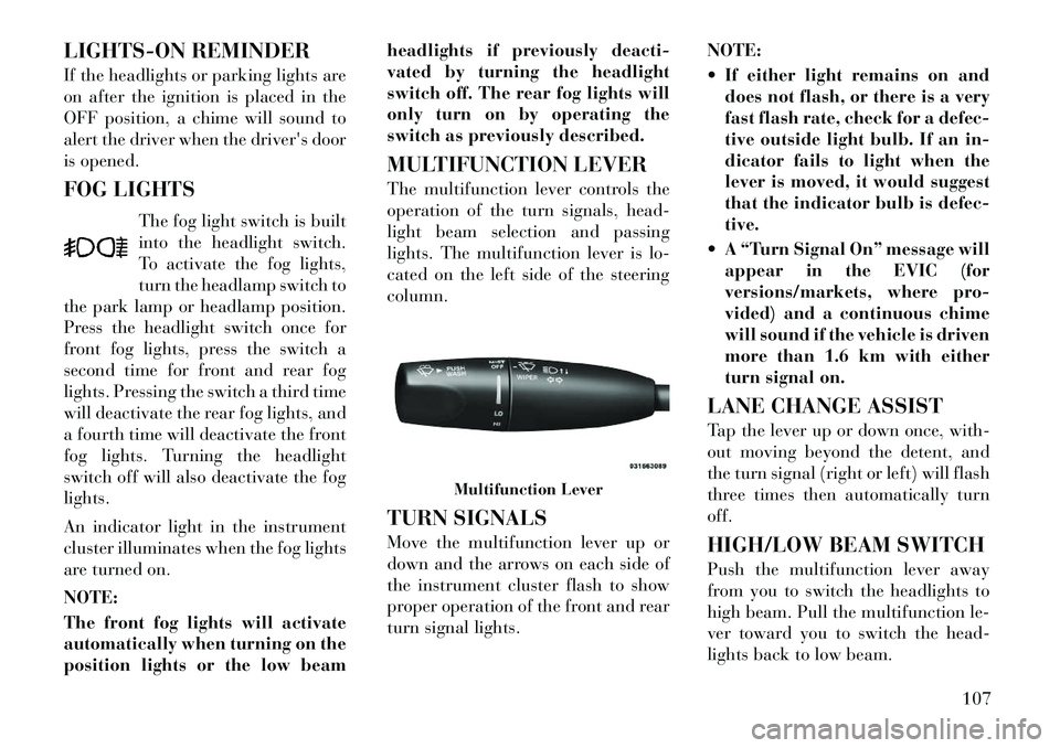
MULTIFUNCTION LEVER
The multifunction lever controls the
operation of the turn signals, head-
light beam selection and passing
lights. The multifunction lever is lo-
cated on the left side of the steering
column.
TURN SIGNALS
Move the multifunction lever up or
down and the arrows on each side of
the instrument cluster flash to show
proper operation of the front and rear
turn signal lights.
NOTE:
If either light remains on and
does not flash, or there is a very
fast flash rate, check for a defec-
tive outside light bulb. If an in-
dicator fails to light when the
lever is moved, it would suggest
that the indicator bulb is defec-
tive.
A “Turn Signal On” message will appear in the EVIC (for
versions/markets, where pro-
vided) and a continuous chime
will sound if the vehicle is driven
more than 1.6 km with either
turn signal on.
LANE CHANGE ASSIST
Tap the lever up or down once, with-
out moving beyond the detent, and
the turn signal (right or left) will flash
three times then automatically turn
off.
HIGH/LOW BEAM SWITCH
Push the multifunction lever away
from you to switch the headlights to
high beam. Pull the multifunction le-
ver toward you to switch the head-
lights back to low beam.
Multifunction Lever
107
Page 129 of 316

ADAPTIVE CRUISE
CONTROL (ACC) MENU
The EVIC displays the current ACC
system settings. The EVIC is located
in the upper part of the instrument
cluster between the speedometer and
the tachometer. The information it
displays depends on ACC system sta-
tus.
UP and DOWN Buttons
Press the MENU button (located on
the steering wheel) repeatedly until
one of the following displays in the
EVIC:
Adaptive Cruise Control Off� When ACC is deactivated, the display will read “Adaptive
Cruise Control Off.”
Adaptive Cruise Control Ready � When ACC is activated but the vehicle speed setting has not
been selected, the display will
read “Adaptive Cruise Control
Ready.” ACC SET
� When ACC is set, the set speed will display.
The set speed will continue to
display in place of the odometer
reading when changing the
EVIC display while ACC is set.
The ACC screen will display once
again if any ACC activity occurs,
which may include any of the follow-
ing:
Set Speed Change
Distance Setting Change
System Cancel
Driver Override
System Off
ACC Proximity Warning
ACC Unavailable Warning
The EVIC will return to the last
display selected after five sec-
onds of no ACC display activity.
Brake Alert 3Brake Alert 2Brake Alert 1
123
Page 137 of 316

WARNING ALERTS
Rear Distance
(in/cm) Greater than
150 cm 150-100 cm 100-60 cm 60-35 cm Less than 35 cm
Front Distance (cm) Greater than
120 cm 120-100 cm 100-60 cm 60-35 cm Less than 35 cm
Audible Alert (Chime) NoneSingle 1/2 second
tone (for rear only) Slow (for rear
only) Fast
Continuous
Arc None3 Solid
(Continuous) 3 Slow Flashing 2 Slow Flashing 1 Slow Flashing
FRONT PARK ASSIST
AUDIBLE ALERTS
ParkSense® will turn off the Front
Park Assist audible alert (chime) after
approximately 4 seconds when an ob-
stacle has been detected, the vehicle is
stationary, and brake pedal is applied.
ENABLING AND
DISABLING PARKSENSE®
ParkSense® can be enabled and dis-
abled using the Uconnect Touch™
System. The available choices are:
Off, Sound Only, or Sound and Dis-
play. Refer to “Uconnect Touch™ Set-
tings” in “Understanding Your In-
strument Panel” for further
information. When the ParkSense® soft-key is
pressed to disable the system, the
EVIC will display the “PARK ASSIST
SYSTEM OFF” message for approxi-
mately five seconds. Refer to “Elec-
tronic Vehicle Information Center
(EVIC)” in “Understanding Your In-
strument Panel” for further informa-
tion. When the shift lever is moved to
REVERSE or to DRIVE (at or below
11 km/h) and the system is disabled,
the EVIC will display the “PARK AS-
SIST SYSTEM OFF” message for ap-
proximately five seconds in RE-
VERSE or for 5 seconds when the
vehicle is in DRIVE.
SERVICE THE
PARKSENSE® PARK
ASSIST SYSTEM
When the ParkSense® Park Assist
System is malfunctioning, the instru-
ment cluster will actuate a single
chime, once per ignition cycle. The
instrument cluster will display the
“CLEAN PARK ASSIST” message
when any of the rear or front sensor(s)
are blocked by snow, mud, or ice and
the vehicle is shifted into REVERSE
or DRIVE. The instrument cluster
will display the “SERVICE PARK AS-
SIST” message when any of the rear
or front sensors are damaged and re-
quire service. When the shift lever is
moved to REVERSE or DRIVE and
the system has detected a faulted con-
131
Page 155 of 316

4
UNDERSTANDING YOUR INSTRUMENT
PANEL
INSTRUMENT PANEL FEATURES . . . . . . . . . . . 152
INSTRUMENT CLUSTER . . . . . . . . . . . . . . . . . . 153
INSTRUMENT CLUSTER DESCRIPTIONS . . . . 154
ELECTRONIC VEHICLE INFORMATION CENTER (EVIC) . . . . . . . . . . . . . . . . . . . . . . . . . 159
ELECTRONIC VEHICLE INFORMATION CENTER (EVIC) DISPLAYS . . . . . . . . . . . . . . 160
EVIC WHITE TELLTALES . . . . . . . . . . . . . . . 161
EVIC AMBER TELLTALES . . . . . . . . . . . . . . . 162
EVIC RED TELLTALES . . . . . . . . . . . . . . . . . 162
OIL CHANGE DUE . . . . . . . . . . . . . . . . . . . . . 164
DIESEL PARTICULATE FILTER (DPF) MESSAGES . . . . . . . . . . . . . . . . . . . . . . . . . . 164
FUEL ECONOMY . . . . . . . . . . . . . . . . . . . . . . 165
CRUISE CONTROL . . . . . . . . . . . . . . . . . . . . 165
VEHICLE SPEED . . . . . . . . . . . . . . . . . . . . . . 166
TRIP INFO . . . . . . . . . . . . . . . . . . . . . . . . . . . 166
TIRE BAR . . . . . . . . . . . . . . . . . . . . . . . . . . . 166
VEHICLE INFO (CUSTOMER INFORMATION FEATURES) . . . . . . . . . . . . . . 167
149
Page 158 of 316
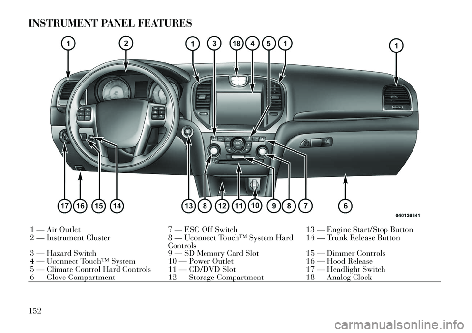
INSTRUMENT PANEL FEATURES1 — Air Outlet7 — ESC Off Switch13 — Engine Start/Stop Button
2 — Instrument Cluster 8 — Uconnect Touch™ System Hard
Controls 14 — Trunk Release Button
3 — Hazard Switch 9 — SD Memory Card Slot15 — Dimmer Controls
4 — Uconnect Touch™ System 10 — Power Outlet 16 — Hood Release
5 — Climate Control Hard Controls 11 — CD/DVD Slot 17 — Headlight Switch
6 — Glove Compartment 12 — Storage Compartment18 — Analog Clock
152
Page 159 of 316

INSTRUMENT CLUSTER
153