turn signal bulb Lancia Thema 2012 Owner handbook (in English)
[x] Cancel search | Manufacturer: LANCIA, Model Year: 2012, Model line: Thema, Model: Lancia Thema 2012Pages: 316, PDF Size: 3.85 MB
Page 44 of 316
ACC position, or not in the ignition,
the air bag system is not on and the air
bags will not inflate.
The ORC contains a backup power
supply system that may deploy the air
bags even if the battery loses power or
it becomes disconnected prior to de-
ployment.Also, the ORC turns on the
Air Bag Warning Light in
the instrument panel for
approximately four to eight
seconds for a self-check when the ig-
nition is first turned on. After the self-
check, the Air Bag Warning Light will
turn off. If the ORC detects a mal-
function in any part of the system, it
turns on the Air Bag Warning Light,
either momentarily or continuously. A
single chime will sound if the light
comes on again after initial startup.
It also includes diagnostics that will
illuminate the instrument cluster Air
Bag Warning Light if a malfunction is
noted that could affect the air bag
system. The diagnostics also record
the nature of the malfunction.
WARNING!
Ignoring the Air Bag Warning Light
in your instrument panel could
mean you won't have the air bags to
protect you in a collision. If the light
does not come on as a bulb check
when the ignition is first turned on,
stays on after you start the vehicle,
or if it comes on as you drive, have
an authorized dealer service the air
bag system immediately.
Driver And Passenger Advanced
Front Air Bag Inflator Units
The Driver and Passenger Advanced
Front Air Bag Inflator Units are lo-
cated in the center of the steering
wheel and on the right side of the
instrument panel. When the ORC de-
tects a collision requiring the Ad-
vanced Front Air Bags, it signals the
inflator units. A large quantity of non-
toxic gas is generated to inflate the
Advanced Front Air Bags. Different
air bag inflation rates are possible,
based on the collision type and sever-
ity. The steering wheel hub trim cover
and the upper right side of the instru-
ment panel separate and fold out of the way as the air bags inflate to their
full size. The air bags fully inflate in
about 50 to 70 milliseconds. This is
about half of the time it takes to blink
your eyes. The air bags then quickly
deflate while helping to restrain the
driver and front passenger.
The Advanced Front Air Bag gas is
vented through the vent holes in the
sides of the air bag. In this way, the air
bags do not interfere with your con-
trol of the vehicle.
Supplemental Driver Side Knee
Air Bag Inflator Unit (for
versions/markets, where
provided)
The Supplemental Driver Side Knee
Air Bag unit is located in the instru-
ment panel trim beneath the steering
column. When the ORC detects a col-
lision requiring the air bag, it signals
the inflator units. A large quantity of
non-toxic gas is generated to inflate
the Supplemental Driver Side Knee
Air Bag. The trim cover separates and
folds out of the way allowing the air
bag to inflate to the full size. The air
bag fully inflates in about 15 to 20
milliseconds. The Supplemental
38
Page 113 of 316
LIGHTS-ON REMINDER
If the headlights or parking lights are
on after the ignition is placed in the
OFF position, a chime will sound to
alert the driver when the driver's door
is opened.
FOG LIGHTSThe fog light switch is built
into the headlight switch.
To activate the fog lights,
turn the headlamp switch to
the park lamp or headlamp position.
Press the headlight switch once for
front fog lights, press the switch a
second time for front and rear fog
lights. Pressing the switch a third time
will deactivate the rear fog lights, and
a fourth time will deactivate the front
fog lights. Turning the headlight
switch off will also deactivate the fog
lights.
An indicator light in the instrument
cluster illuminates when the fog lights
are turned on.
NOTE:
The front fog lights will activate
automatically when turning on the
position lights or the low beam headlights if previously deacti-
vated by turning the headlight
switch off. The rear fog lights will
only turn on by operating the
switch as previously described.
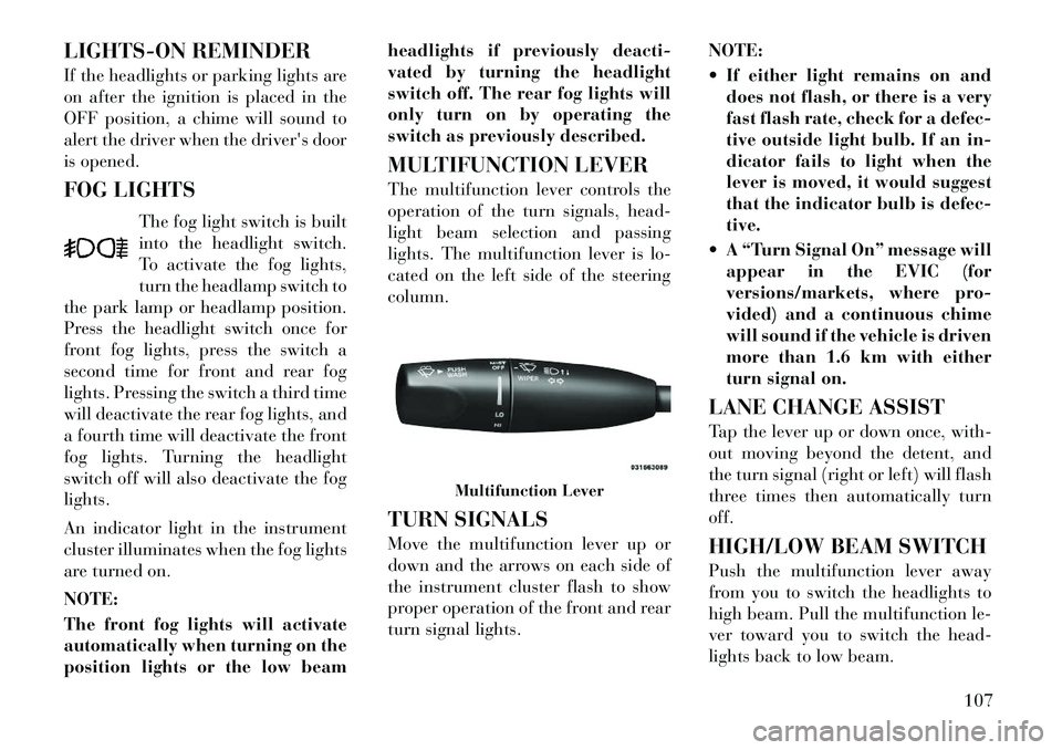
MULTIFUNCTION LEVER
The multifunction lever controls the
operation of the turn signals, head-
light beam selection and passing
lights. The multifunction lever is lo-
cated on the left side of the steering
column.
TURN SIGNALS
Move the multifunction lever up or
down and the arrows on each side of
the instrument cluster flash to show
proper operation of the front and rear
turn signal lights.
NOTE:
If either light remains on and
does not flash, or there is a very
fast flash rate, check for a defec-
tive outside light bulb. If an in-
dicator fails to light when the
lever is moved, it would suggest
that the indicator bulb is defec-
tive.
A “Turn Signal On” message will appear in the EVIC (for
versions/markets, where pro-
vided) and a continuous chime
will sound if the vehicle is driven
more than 1.6 km with either
turn signal on.
LANE CHANGE ASSIST
Tap the lever up or down once, with-
out moving beyond the detent, and
the turn signal (right or left) will flash
three times then automatically turn
off.
HIGH/LOW BEAM SWITCH
Push the multifunction lever away
from you to switch the headlights to
high beam. Pull the multifunction le-
ver toward you to switch the head-
lights back to low beam.
Multifunction Lever
107
Page 160 of 316

INSTRUMENT CLUSTER
DESCRIPTIONS
1. TachometerThis gauge measures engine
revolutions-per-minute (RPM x 1000).2. Park/Headlight ON Indicator
(for versions/markets, where
provided)This indicator will illumi-
nate when the park lights or
headlights are turned on.
3. Turn Signal Indicators The arrow will flash with
the exterior turn signal
when the turn signal lever is
operated.
If the vehicle electronics sense that the
vehicle is driven more than 1.6 km
with either turn signal on, a continu-
ous chime will sound to alert you to
turn the signals off. If either indicator
flashes at a rapid rate, check for a
defective outside light bulb. 4. Front Fog Light Indicator (for
versions/markets, where provided)
This indicator will illuminate
when the front fog lights are on.
5. Rear Fog Light Indicator (for
versions/markets, where provided)
This indicator will illuminate
when the rear fog lights are on.
6. High Beam Indicator
This indicator shows that the
high beam headlights are on.
Push the multifunction lever
forward to switch the headlights to
high beam, and pull toward yourself
(normal position) to return to low
beam.
7. Odometer Display / Electronic
Vehicle Information Center (EVIC)
Display
Odometer Display
The odometer display shows the total
distance the vehicle has been driven. Electronic Vehicle Information
Center (EVIC) Display
The Electronic Vehicle Information
Center (EVIC) features a driver-
interactive display that is located in
the instrument cluster. For further in-
formation, refer to “Electronic Ve-
hicle Information Center (EVIC)”.
The Shift Lever Indicator is self-
contained within the EVIC display. It
displays the gear position of the auto-
matic transmission.
NOTE:
You must apply the brakes be-
fore shifting from PARK.
The highest available transmis-
sion gear is displayed in the
lower right corner of the Elec-
tronic Vehicle Information Cen-
ter (EVIC) whenever the Elec-
tronic Range Select (ERS)
feature is active. Use the +/- se-
lector on the shift lever to acti-
vate ERS. Refer to “Automatic
Transmission” in “Starting And
Operating” for further informa-
tion.
154
Page 260 of 316
EXHAUST SYSTEM . . . . . . . . . . . . . . . . . . . . 264
COOLING SYSTEM . . . . . . . . . . . . . . . . . . . . 265
BRAKE SYSTEM . . . . . . . . . . . . . . . . . . . . . . 268
AUTOMATIC TRANSMISSION . . . . . . . . . . . . 270
REAR AXLE . . . . . . . . . . . . . . . . . . . . . . . . . . 271
APPEARANCE CARE AND PROTECTIONFROM CORROSION . . . . . . . . . . . . . . . . . . . . 271
FUSES . . . . . . . . . . . . . . . . . . . . . . . . . . . . . . . . 274 Integrated Power Module . . . . . . . . . . . . . . . . 274
Rear Power Distribution Center . . . . . . . . . . . 276
VEHICLE STORAGE . . . . . . . . . . . . . . . . . . . . . 279
REPLACEMENT BULBS . . . . . . . . . . . . . . . . . . 280
BULB REPLACEMENT . . . . . . . . . . . . . . . . . . . 281 LOW BEAM HEADLAMP, HIGH BEAMHEADLAMP, PARK/TURN LAMP, INNER
PARK LAMP, AND OUTER PARK LAMP . . . . 281
FRONT TURN SIGNAL LAMPS . . . . . . . . . . . 282
REAR TURN SIGNAL AND BACKUP LAMPS . . . . . . . . . . . . . . . . . . . . . . . . . . . . . 282
LICENSE LAMP . . . . . . . . . . . . . . . . . . . . . . . 283
FLUID CAPACITIES . . . . . . . . . . . . . . . . . . . . . . 283
FLUIDS, LUBRICANTS, AND GENUINE PARTS . . . . . . . . . . . . . . . . . . . . . . . . . . . . . . . . 284
ENGINE . . . . . . . . . . . . . . . . . . . . . . . . . . . . . 284
CHASSIS . . . . . . . . . . . . . . . . . . . . . . . . . . . . 285
254
Page 286 of 316
2. Anytime you store your vehicle, or
keep it out of service (i.e., vacation)
for two weeks or more, run the air
conditioning system at idle for about
five minutes in the fresh air and high
blower setting. This will ensure ad-
equate system lubrication to minimize
the possibility of compressor damage
when the system is started again.
REPLACEMENT BULBS
Interior Bulb Number
Rear Courtesy/Reading
Lamps . . . . . . . . . . . . . . . . . W5W
Rear Compartment (Trunk)
Lamp . . . . . . . . . . . . . . . . . . . 562
Overhead Console Reading
Lamps . . . . . . . . . . . . . . . . . . 578
Visor Vanity Lamps . . . . . . . . . 194
Glove Box Lamp (for versions/
markets, where provided) . . . . . 194
Door Courtesy . . . . . . . . . . . . . 562
Shift Indicator Lamp . . JKLE14140
Optional Door Map Pocket/Cup-
holder . . . . . . . . . . . . . . . . . . LED(Serviced at Authorized Dealer) NOTE:
For lighted switches, see your au-
thorized dealer for replacement
instructions.
All of the interior bulbs are glass
wedge base or glass cartridge types.
Aluminum base bulbs are not ap-
proved and should not be used for
replacement.
Exterior
Bulb Number
Low Beam/High Beam (Bi-Xenon
Headlamp) . . . . . . . . . . . . . . . D3S
(Serviced at Authorized Dealer)
Front Turn Signal
Lamp . . . . . . . . . . . . . PSY24WSV
Front Park Lamp . . . . . . . . . . LED
(Serviced at Authorized Dealer)
Daytime Running Lamp . . . . . LED
(Serviced at Authorized Dealer)
Front Fog Lamp (for versions/
markets, where provided) . . . . H11
Front Position Lamp . . . . . . . LED
(Serviced at Authorized Dealer)
Front Side Marker Lamp . . . . LED
(Serviced at Authorized Dealer)
Side Repeater Lamps . . . . . . . LED
(Serviced at Authorized Dealer) Rear Tail/Stop/Side Marker
Lamp . . . . . . . . . . . . . . . . . . LED
(Serviced at Authorized Dealer)
Rear Turn Signal Lamp . . . WY21W
Rear Fog Lamps . . . . . . . . . . LED
(Serviced at Authorized Dealer)
Backup Lamp . . . . . . . . . . . W16W
Center High Mount Stop Lamp
(CHMSL) . . . . . . . . . . . . . . . LED
(Serviced at Authorized Dealer)
License . . . . . . . . . . . . . . . . W5W
280
Page 288 of 316
2. Twist the appropriate bulb and
socket assembly counterclockwise,
and then pull it out of the headlamp
assembly.
3. Disconnect the bulb from the
socket assembly and install the re-
placement bulb.
4. Reinstall the bulb and socket as-
sembly into the headlamp assembly,
and then turn it clockwise.CAUTION!Do not touch the new bulb with your
fingers. Oil contamination will se-
verely shorten bulb life. If the bulb
comes in contact with an oily surface,
clean the bulb with rubbing alcohol.FRONT TURN SIGNAL
LAMPS
1. Open the hood.
NOTE:
Removal of the air cleaner filter
housing may be necessary prior toreplacing bulbs in the headlamp
assembly on the driver side of the
vehicle.
2. Remove plastic cap from the back
of the headlamp housing.
3. Squeeze the two tabs on the side of
the turn signal bulb socket and pull
straight out from the lamp.
4. Install replacement bulb and con-
nector assembly straight into the
lamp until it locks in place.
5. Reinstall plastic cap to headlamp
assembly housing.
REAR TURN SIGNAL AND
BACKUP LAMPS
1. Open the trunk.
2.
Remove the trunk trim by removing
the grocery hook (using a T-20 torx
driver or similar tool), remove the fas-
tener, and pull back the weather strip.
3. Pull back the trunk liner to gain
access to the tail lamp wing nuts.
4. Remove the three wing nuts from
the back of the tail lamp assembly. 5. Pull the tail lamp assembly away
from the vehicle enough to access the
electrical connector.
6. Push the electrical connector lock-
ing tab to the side.
7.
Disconnect the electrical connector.
8. Continue removing lamp from ve-
hicle in order to access the bulb(s).
9. Turn the appropriate bulb and
socket assembly counterclockwise to
remove it from the tail lamp assembly.
10. Disconnect the bulb from the
socket assembly and install the re-
placement bulb.
11. Reinstall the bulb and socket as-
sembly into the tail lamp assembly,
and then turn it clockwise.
12. Reinstall the tail lamp assembly,
fasteners, electrical connector, and
trunk trim.
13. Close the trunk.
282
Page 308 of 316
Introduction . . . . . . . . . . . . . . . 4
Jump Starting . . . . . . . . . . . . 246
Key-In Reminder . . . . . . . . . . . 13
Key, Programming . . . . . . . . . . 14
Key, Replacement . . . . . . . . . . 14
Key, Sentry (Immobilizer) . . . . 13
Keyless Enter-N-Go . . . . . . 20,191
Keyless Entry System . . . . . . . . 16
Keyless Go . . . . . . . . . . . . . . . 12
Keys . . . . . . . . . . . . . . . . . . . . 12
Kicker Sound System . . . . . . . 178
Knee Bolster . . . . . . . . . . . . . . 33
Lane Change and Turn
Signals . . . . . . . . . . . . . . . . . 107
Lane Change Assist . . . . . . . . 107
Lap/Shoulder Belts . . . . . . . . . 26
LATCH (Lower Anchors and
Tether for CHildren) . . . . . . 46,47
Latch Plate . . . . . . . . . . . . . . . 27
Latches . . . . . . . . . . . . . . . . . 53
Lead Free Gasoline . . . . . . . . 223
Leaks, Fluid . . . . . . . . . . . . . . 53
Life of Tires . . . . . . . . . . . . . 217
Light Bulbs . . . . . . . . . . . 53,280
Lights . . . . . . . . . . . . . . . 53,104Airbag . . . . . . . . . 38,41,52,156 Alarm . . . . . . . . . . . . . . . . 158
Anti-Lock . . . . . . . . . . . . . 158
Automatic Headlights . . . . . 105
Brake Assist Warning . . . . . 213
Brake Warning . . . . . . . . . . 157
Bulb Replacement . . . . 280,281
Dimmer Switch,
Headlight . . . . . . . . . . . . . 107
Electronic Stability Program
(ESP) Indicator . . . . . . . . . 213
Exterior . . . . . . . . . . . . . . . . 53
Fog . . . . . . . . . . . . . . . . . . 154
Hazard Warning Flasher . . . 240
Headlight Switch . . . . . . . . 104
Headlights . . . . . . . . . 104,281
Headlights On Reminder . . . 107
Headlights On With
Wipers . . . . . . . . . . . . 105,111
High Beam . . . . . . . . . . . . 107
High Beam Indicator . . . . . . 154
High Beam/Low Beam
Select . . . . . . . . . . . . . . . . 107
Illuminated Entry . . . . . . . . . 16
Instrument Cluster . . . . . . . 104
Intensity Control . . . . . . . . 109
Interior . . . . . . . . . . . . . . . 108
License . . . . . . . . . . . . . . . 283
Lights On Reminder . . . . . . 107
Low Fuel . . . . . . . . . . . . . . 162Malfunction Indicator
(Check Engine) . . . . . . . . . 156
Map Reading . . . . . . . . . . . 108
Parade Mode (Daytime
Brightness) . . . . . . . . . . . . 109
Passing . . . . . . . . . . . . . . . 108
Reading . . . . . . . . . . . 108,135
Seat Belt Reminder . . . . . . . 159
Security Alarm (Theft
Alarm) . . . . . . . . . . . . . . . 158
Service . . . . . . . . . . . . 280,281
Service Engine Soon
(Malfunction Indicator) . . . . 156
SmartBeams . . . . . . . . . . . 106
Theft Alarm (Security
Alarm) . . . . . . . . . . . . . . . 158
Tire Pressure Monitoring
(TPMS) . . . . . . . . . . . 155,219
Traction Control . . . . . . . . . 213
Turn Signal . . . . . . . . . . 53,107
Vanity Mirror . . . . . . . . . . . . 65
Wait to Start . . . . . . . . . . . 162
Warning (Instrument Cluster
Description) . . . . . . . . . . . . 154
Load Leveling System . . . . . . 147
Loading Vehicle . . . . . . . 227,228
Capacities . . . . . . . . . . . . . 228
Locks . . . . . . . . . . . . . . . . . . . 18 Auto Unlock . . . . . . . . . . . . 19
302