air condition Lancia Thema 2013 Owner handbook (in English)
[x] Cancel search | Manufacturer: LANCIA, Model Year: 2013, Model line: Thema, Model: Lancia Thema 2013Pages: 336, PDF Size: 3.87 MB
Page 167 of 336

The dual brake system provides a re-
serve braking capacity in the event of
a failure to a portion of the hydraulic
system. A leak in either half of the
dual brake system is indicated by the
Brake Warning Light, which will turn
on when the brake fluid level in the
master cylinder has dropped below a
specified level.
The light will remain on until the
cause is corrected.
NOTE:
The light may flash mo-
mentarily during sharp cornering
maneuvers, which change fluid
level conditions. The vehicle should
have service performed, and the
brake fluid level checked.
If brake failure is indicated, immedi-
ate repair is necessary.WARNING!
Driving a vehicle with the red brake
light on is dangerous. Part of the
brake system may have failed. It
will take longer to stop the vehicle.
You could have a collision. Have the
vehicle checked immediately. Vehicles equipped with the Anti-Lock
Brake System (ABS), are also
equipped with Electronic Brake Force
Distribution (EBD). In the event of an
EBD failure, the Brake Warning Light
will turn on along with the ABS Light.
Immediate repair to the ABS system is
required.
Operation of the Brake Warning Light
can be checked by turning the ignition
switch from the OFF position to the
ON/RUN position. The light should
illuminate for approximately two sec-
onds. The light should then turn off
unless the parking brake is applied or
a brake fault is detected. If the light
does not illuminate, have the light
inspected by an authorized dealer.
The light also will turn on when the
parking brake is applied with the igni-
tion switch in the ON/RUN position.NOTE: This light shows only
that the parking brake is applied.
It does not show the degree of
brake application.
15. Anti-Lock Brake (ABS) Light
This light monitors the
Anti-Lock Brake System
(ABS). The light will turn
on when the ignition switch
is turned to the ON/RUN position and
may stay on for as long as four sec-
onds.
If the ABS light remains on or turns on
while driving, it indicates that the
Anti-Lock portion of the brake sys-
tem is not functioning and that service
is required. However, the conven-
tional brake system will continue to
operate normally if the BRAKE warn-
ing light is not on.
If the ABS light is on, the brake sys-
tem should be serviced as soon as
possible to restore the benefits of
Anti-Lock brakes. If the ABS light
does not turn on when the ignition
switch is turned to the ON/RUN posi-
tion, have the light inspected by an
authorized dealer.
161
Page 169 of 336

CAUTION!
Driving with a hot engine cooling
system could damage your vehicle.
If the temperature gauge reads “H”
pull over and stop the vehicle. Idle
the vehicle with the air conditioner
turned off until the pointer drops
back into the normal range. If the
pointer remains on the “H” and you
hear continuous chimes, turn the
engine off immediately and call an
authorized studio for service.WARNING!
A hot engine cooling system is dan-
gerous. You or others could be
badly burned by steam or boiling
coolant. You may want to call an
authorized dealer for service if your
vehicle overheats. If you decide to
look under the hood yourself, see
“Maintaining Your Vehicle”. Fol-
low the warnings under the Cooling
System Pressure Cap paragraph.21. AWD (All Wheel Drive)
Indicator (for versions/ markets,
where provided)
The AWD indicator will illuminate
when All Wheel Drive (AWD) is
activated.
ELECTRONIC VEHICLE
INFORMATION CENTER
(EVIC)
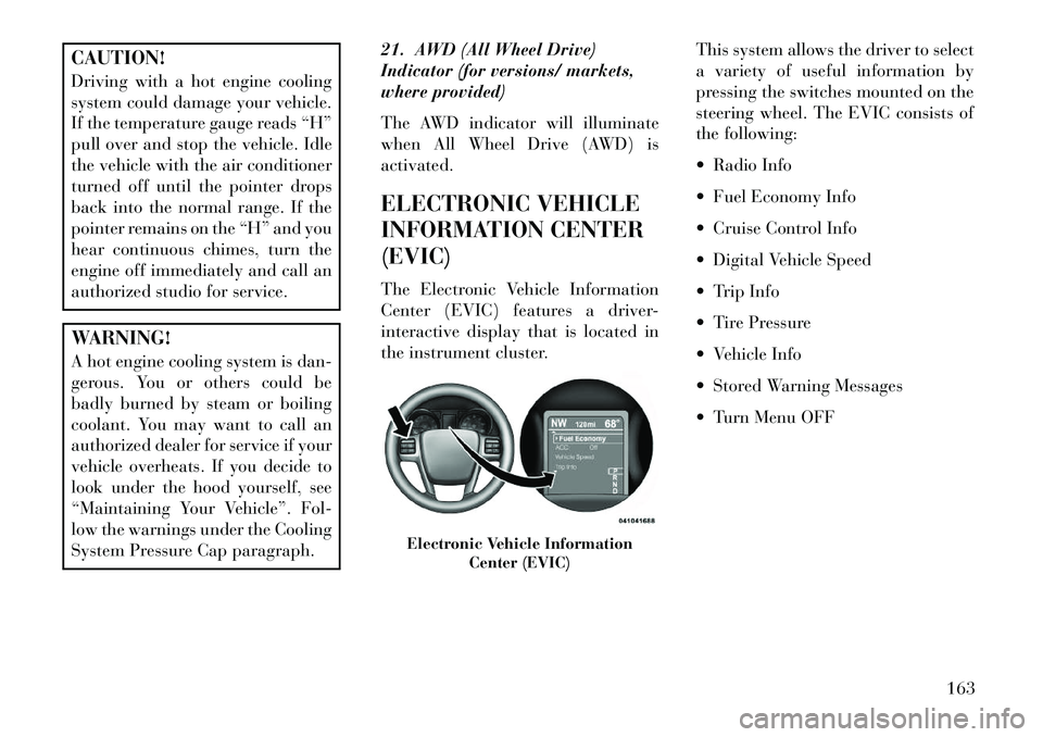
The Electronic Vehicle Information
Center (EVIC) features a driver-
interactive display that is located in
the instrument cluster.
This system allows the driver to select
a variety of useful information by
pressing the switches mounted on the
steering wheel. The EVIC consists of
the following:
Radio Info
Fuel Economy Info
Cruise Control Info
Digital Vehicle Speed
Trip Info
Tire Pressure
Vehicle Info
Stored Warning Messages
Turn Menu OFF
Electronic Vehicle Information
Center (EVIC)
163
Page 190 of 336

CD/DVD DISC
MAINTENANCE
To keep a CD/DVD in good condition,
take the following precautions:
1. Handle the disc by its edge; avoid
touching the surface.
2. If the disc is stained, clean the
surface with a soft cloth, wiping from
center to edge.
3. Do not apply paper or tape to the
disc; avoid scratching the disc.
4. Do not use solvents such as ben-
zene, thinner, cleaners, or anti-static
sprays.
5. Store the disc in its case after play-
ing.
6. Do not expose the disc to direct
sunlight.
7. Do not store the disc where tem-
peratures may become too high.
NOTE: If you experience diffi-
culty in playing a particular disc, it
may be damaged (i.e., scratched,
reflective coating removed, a hair,moisture or dew on the disc) over-
sized, or have protection encoding.
Try a known good disc before con-
sidering disc player service.
RADIO OPERATION AND
MOBILE PHONES
Under certain conditions, the mobile
phone being on in your vehicle can
cause erratic or noisy performance
from your radio. This condition may
be lessened or eliminated by relocat-
ing the mobile phone antenna. This
condition is not harmful to the radio.
If your radio performance does not
satisfactorily “clear” by the reposi-
tioning of the antenna, it is recom-
mended that the radio volume be
turned down or off during mobile
phone operation.
CLIMATE CONTROLS
The air conditioning and heating sys-
tem is designed to make you comfort-
able in all types of weather. This sys-
tem can be operated through either
the Automatic Climate Controls on
the instrument panel or through the
Uconnect Touch™ system display.When the Uconnect Touch™ system
is in different modes (Radio, Player,
Settings, More, etc.) the driver and
passenger temperature settings will be
indicated at the top of the display.
GENERAL OVERVIEW
Hard-Keys
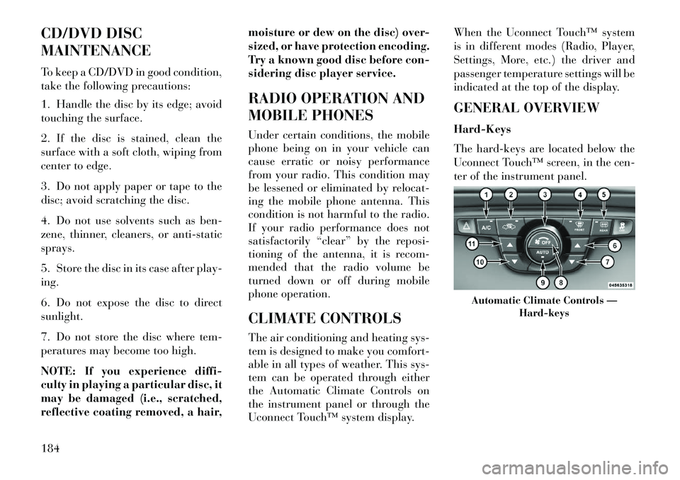
The hard-keys are located below the
Uconnect Touch™ screen, in the cen-
ter of the instrument panel.
Automatic Climate Controls —
Hard-keys
184
Page 191 of 336

Soft-Keys
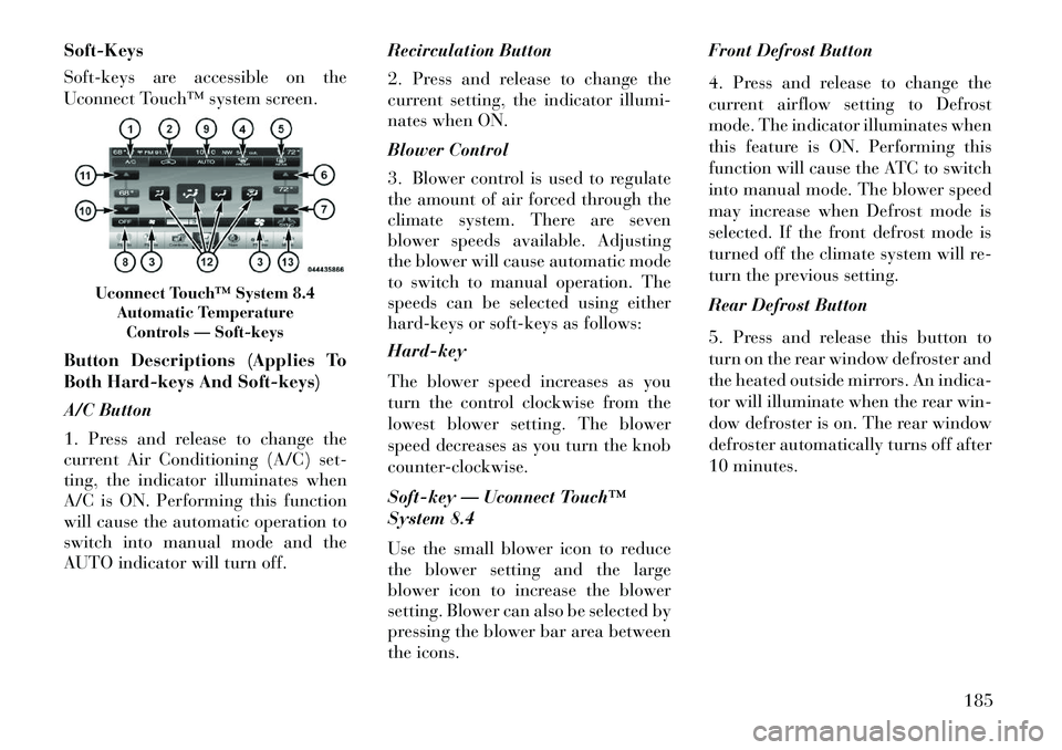
Soft-keys are accessible on the
Uconnect Touch™ system screen.
Button Descriptions (Applies To
Both Hard-keys And Soft-keys)
A/C Button
1. Press and release to change the
current Air Conditioning (A/C) set-
ting, the indicator illuminates when
A/C is ON. Performing this function
will cause the automatic operation to
switch into manual mode and the
AUTO indicator will turn off.Recirculation Button
2. Press and release to change the
current setting, the indicator illumi-
nates when ON.
Blower Control
3. Blower control is used to regulate
the amount of air forced through the
climate system. There are seven
blower speeds available. Adjusting
the blower will cause automatic mode
to switch to manual operation. The
speeds can be selected using either
hard-keys or soft-keys as follows:
Hard-key
The blower speed increases as you
turn the control clockwise from the
lowest blower setting. The blower
speed decreases as you turn the knob
counter-clockwise.
Soft-key — Uconnect Touch™
System 8.4
Use the small blower icon to reduce
the blower setting and the large
blower icon to increase the blower
setting. Blower can also be selected by
pressing the blower bar area between
the icons.Front Defrost Button
4. Press and release to change the
current airflow setting to Defrost
mode. The indicator illuminates when
this feature is ON. Performing this
function will cause the ATC to switch
into manual mode. The blower speed
may increase when Defrost mode is
selected. If the front defrost mode is
turned off the climate system will re-
turn the previous setting.
Rear Defrost Button
5. Press and release this button to
turn on the rear window defroster and
the heated outside mirrors. An indica-
tor will illuminate when the rear win-
dow defroster is on. The rear window
defroster automatically turns off after
10 minutes.
Uconnect Touch™ System 8.4
Automatic TemperatureControls — Soft-keys
185
Page 193 of 336

down or side to side to regulate air-
flow direction. There is a shut off
wheel located below the air vanes to
shut off or adjust the amount of air-
flow from these outlets.
Bi-Level ModeAir comes from the instrument
panel outlets and floor outlets.
A slight amount of air is di-
rected through the defrost and side
window demister outlets.
NOTE: BI-LEVEL mode is de-
signed under comfort conditions
to provide cooler air out of the
panel outlets and warmer air from
the floor outlets.
Floor Mode
Air comes from the floor out-
lets. A slight amount of air is
directed through the defrost
and side window demister outlets.
Mix Mode
Air comes from the floor,
defrost and side window
demist outlets. This mode works
best in cold or snowy conditions.
Defrost Mode Air comes from the windshield
and side window demist out-
lets. Use Defrost mode with
maximum temperature settings for
best windshield and side window de-
frosting and defogging. When the de-
frost mode is selected, the blower level
may increase.
SYNC
13. Press the Sync soft-key to toggle
the Sync feature On/Off. The Sync
indicator is illuminated when this fea-
ture is enabled. Sync is used to syn-
chronize the passenger temperature
setting with the driver temperature
setting. Changing the passenger tem-
perature setting while in Sync will
automatically exit this feature.
CLIMATE CONTROL
FUNCTIONS
A/C (Air Conditioning)
The Air Conditioning (A/C) button
allows the operator to manually acti-
vate or deactivate the air conditioning
system. When the air conditioning system is turned on, cool dehumidi-
fied air will flow through the outlets
into the cabin. For improved fuel
economy, press the A/C button to turn
off the air conditioning and manually
adjust the blower and airflow mode
settings.
NOTE:
If fog or mist appears on the wind-
shield or side glass, select Defrost
mode and increase blower speed. If your air conditioning perfor-
mance seems lower than ex-
pected, check the front of the
A/C condenser (located in front
of the radiator), for an accumu-
lation of dirt or insects. Clean
with a gentle water spray from
behind the radiator and through
the condenser.
Recirculation When outside air contains
smoke, odors, or high hu-
midity, or if rapid cooling is
desired, you may wish to
recirculate interior air by pressing the
187
Page 195 of 336

The operator can also select the direc-
tion of the airflow by selecting one of
the available mode settings. A/C op-
eration and Recirculation control can
also be manually selected in Manual
operation.
OPERATING TIPS
NOTE:
Refer to the chart at the
end of this section for suggested
control settings for various weather
conditions.
Summer OperationThe engine cooling system in air-
conditioned vehicles must be protected
with a high-quality antifreeze coolant
to provide proper corrosion protection
and to protect against engine overheat-
ing. A solution of 50% glycol antifreeze
coolant and 50% water is recom-
mended. Refer to “Maintenance Proce-
dures” in “Maintaining Your Vehicle”
for proper coolant selection.
Winter OperationUse of the air Recirculation mode dur-
ing Winter months is not recommended
because it may cause window fogging.Vacation Storage
Any time you store your vehicle or
keep it out of service (i.e., vacation)
for two weeks or more, run the air
conditioning system at idle for about
five minutes in the fresh air and high
blower setting. This will ensure ad-
equate system lubrication to minimize
the possibility of compressor damage
when the system is started again.
Window Fogging
Interior fogging on the windshield can
be quickly removed by turning the
mode selector to Defrost. The Defrost/
Floor mode can be used to maintain a
clear windshield and provide suffi-
cient heating. If side window fogging
becomes a problem increase blower
speed. Vehicle windows tend to fog on
the inside in mild but rainy or humid
weather. NOTE:
Recirculate without A/C should
not be used for long periods, as
fogging may occur.Automatic Temperature Controls
(ATC) will automatically adjust
the climate control settings to re-
duce or eliminate window fogging
on the front windshield. When
this occurs, recirculation will be
unavailable.A/C Air Filter
The climate control system filters out-
side air containing dust, pollen and
some odors. Strong odors cannot be
totally filtered out. Refer to “Mainte-
nance Procedures” in “Maintaining
Your Vehicle” for filter replacement
instructions.
189
Page 204 of 336

2. With your foot on the brake pedal,
press the ENGINE START/STOP
button.
3. Watch the “Wait To Start Light” in
the instrument cluster. Refer to “In-
strument Cluster” in “Understanding
Your Instrument Panel” for further
information. It may glow for up to
three seconds, depending on engine
temperature.
4.
When the “Wait To Start Light”
goes out, the engine will automatically
start.
5. After the engine starts, allow it to
idle for approximately 30 seconds be-
fore driving. This allows oil to circu-
late and lubricate the turbocharger.
Engine Warm UpAvoid full throttle operation when the
engine is cold. When starting a cold
engine, bring the engine up to operating
speed slowly to allow the oil pressure to
stabilize as the engine warms up.
NOTE:
High-speed, no-load run-
ning of a cold engine can result in
excessive white smoke and poor
engine performance. No-load en-
gine speeds should be kept under
1,200 RPM during the warm-up pe-
riod, especially in cold ambient
temperature conditions.
If temperatures are below 0°C, oper-
ate the engine at moderate speeds
for five minutes before full loads are
applied.
Engine Idling – In Cold Weather
Avoid prolonged idling in ambient
temperatures below 18°C. Long pe-
riods of idling may be harmful to your
engine because combustion chamber
temperatures can drop so low that the
fuel may not burn completely. Incom-
plete combustion allows carbon and
varnish to form on piston rings and
injector nozzles. Also, the unburned
fuel can enter the crankcase, diluting
the oil and causing rapid wear to the
engine. Stopping The Engine
Before turning off your turbo diesel
engine, always allow the engine to
return to normal idle speed and run
for several seconds. This assures
proper lubrication of the turbo-
charger. This is particularly necessary
after any period of hard driving.
Idle the engine a few minutes before
routine shutdown. After full load op-
eration, idle the engine three to five
minutes before shutting it down. This
idle period will allow the lubricating
oil and coolant to carry excess heat
away from the combustion chamber,
bearings, internal components, and
turbocharger. This is especially im-
portant for turbocharged, charge air
cooled engines.
198
Page 235 of 336

CAUTION!
After inspecting or adjusting the
tire pressure, always reinstall the
valve stem cap. This will prevent
moisture and dirt from entering the
valve stem, which could damage
the valve stem.
Inflation pressures specified on the
placard are always “cold tire inflation
pressure.” Cold tire inflation pressure
is defined as the tire pressure after the
vehicle has not been driven for at least
three hours, or driven less than
1.6 km after a three hour period. The
cold tire inflation pressure must not
exceed the maximum inflation pres-
sure molded into the tire sidewall.
Check tire pressures more often if
subject to a wide range of outdoor
temperatures, as tire pressures vary
with temperature changes.
Tire pressures change by approxi-
mately 0.07 BAR per 7°C of air tem-
perature change. Keep this in mind
when checking tire pressure inside a
garage, especially in the Winter. Example: If garage temperature =
20°C and the outside temperature =
0°C then the cold tire inflation pres-
sure should be increased by
0.21 BAR, which equals 0.07 kPa for
every 7°C for this outside temperature
condition.
Tire pressure may increase from 0.13
to 0.4 BAR during operation. DO
NOT reduce this normal pressure
build up or your tire pressure will be
too low.
TIRE PRESSURES FOR
HIGH SPEED OPERATION
The manufacturer advocates driving
at safe speeds within posted speed
limits. Where speed limits or condi-
tions are such that the vehicle can be
driven at high speeds, maintaining
correct tire inflation pressure is very
important. Increased tire pressure
and reduced vehicle loading may be
required for high-speed vehicle op-
eration. Refer to original equipment
or an authorized tire dealer for recom-
mended safe operating speeds, load-
ing and cold tire inflation pressures.
WARNING!
High speed driving with your ve-
hicle under maximum load is dan-
gerous. The added strain on your
tires could cause them to fail. You
could have a serious collision. Do
not drive a vehicle loaded to the
maximum capacity at continuous
speeds above 120 km/h.
RADIAL PLY TIRESWARNING!
Combining radial ply tires with
other types of tires on your vehicle
will cause your vehicle to handle
poorly. The instability could cause
a collision. Always use radial ply
tires in sets of four. Never combine
them with other types of tires.
Cuts and punctures in radial tires are
repairable only in the tread area be-
cause of sidewall flexing. Consult
your authorized tire dealer for radial
tire repairs.
229
Page 236 of 336

COMPACT SPARE TIRE
(for versions/markets,
where provided)The compact spare is for temporary
emergency use only. You can identify if
your vehicle is equipped with a com-
pact spare by looking at the spare tire
description on the Tire and Loading
Information Placard located on the
driver’s side door opening or on the
sidewall of the tire. Compact spare tire
descriptions begin with the letter “T”
or “S” preceding the size designation.
Example: T145/80D18 103M.T, S = Temporary Spare TireSince this tire has limited tread life the
original equipment tire should be re-
paired (or replaced) and reinstalled on
your vehicle at the first opportunity.Do not install a wheel cover or at-
tempt to mount a conventional tire on
the compact spare wheel, since the
wheel is designed specifically for the
compact spare tire. Do not install
more than one compact spare tire and
wheel on the vehicle at any given time
WARNING!
Compact spares are for temporary
emergency use only. With these
spares, do not drive more than
50 mph (80 km/h). Temporary use
spares have limited tread life. When
the tread is worn to the tread wear
indicators, the temporary use spare
tire needs to be replaced. Be sure to
follow the warnings, which apply to
your spare. Failure to do so could
result in spare tire failure and loss
of vehicle control.
LIMITED-USE SPARE
(for versions/markets,
where provided)
The limited-use spare tire is for tem-
porary emergency use only. This tire is
identified by a label located on the
limited-use spare wheel. This label
contains the driving limitations for
this spare. This tire may look like the
original equipped tire on the front or
rear axle of your vehicle, but it is not.
Installation of this limited-use spare
tire affects vehicle handling. Since it is not the same as your original equip-
ment tire, replace (or repair) the origi-
nal equipment tire and reinstall on the
vehicle at the first opportunity.
WARNING!
Limited-use spares are for emer-
gency use only. Installation of this
limited-use spare tire affects ve-
hicle handling. With this tire, do
not drive more than the speed listed
on the limit-use spare wheel. Keep
inflated to the cold tire inflation
pressure listed on your Tire and
Loading Information Placard lo-
cated on the driver’s side door
opening. Replace (or repair) the
original equipment tire at the first
opportunity and reinstall it on your
vehicle. Failure to do so could result
in loss of vehicle control.
TIRE SPINNING
When stuck in mud, sand, snow, or ice
conditions, do not spin your vehicle's
wheels faster than 48 km/h or for
longer than 30 seconds continuously
without stopping when you are stuck.
230
Page 246 of 336

WARNING!
Carbon monoxide (CO) in exhaust
gases is deadly. Follow the precau-
tions below to prevent carbon mon-
oxide poisoning:
Do not inhale exhaust gases. They
contain carbon monoxide, a color-
less and odorless gas which can
kill. Never run the engine in a
closed area, such as a garage, and
never sit in a parked vehicle with
the engine running for an extended
period. If the vehicle is stopped in
an open area with the engine run-
ning for more than a short period,
adjust the ventilation system to
force fresh, outside air into the
vehicle.Guard against carbon monoxide
with proper maintenance. Have
the exhaust system inspected every
time the vehicle is raised. Have any
abnormal conditions repaired
promptly. Until repaired, drive
with all side windows fully open.
(Continued)
WARNING!(Continued)
Keep the trunk closed when driv- ing your vehicle to prevent car-
bon monoxide and other poison-
ous exhaust gases from entering
the vehicle.
FUEL REQUIREMENTS
— DIESEL ENGINES
This vehicle must only use pre-
mium diesel fuel that meets the
requirements of EN 590. Biodiesel
blends that meet EN 590 may also
be used.CAUTION!
The manufacturer requires that
you must fuel this vehicle with Ul-
tra Low Sulfur Highway Diesel fuel
(15 ppm Sulfur maximum) and
prohibits the use of Low Sulfur
Highway Diesel fuel (500 ppm Sul-
fur maximum) to avoid damage to
the emissions control system.
WARNING!
Do not use alcohol or gasoline as a
fuel blending agent. They can be
unstable under certain conditions
and hazardous or explosive when
mixed with diesel fuel.
Diesel fuel is seldom completely free
of water. To prevent fuel system
trouble, have the accumulated water
drained from the fuel/water separator
using the fuel/water separator drain
provided. If you buy good quality fuel
and follow the cold weather advice
above, fuel conditioners should not be
required in your vehicle. If available
in your area, a high cetane “pre-
mium” diesel fuel may offer improved
cold-starting and warm-up perfor-
mance.
240