engine Lancia Thema 2013 Owner handbook (in English)
[x] Cancel search | Manufacturer: LANCIA, Model Year: 2013, Model line: Thema, Model: Lancia Thema 2013Pages: 336, PDF Size: 3.87 MB
Page 62 of 336

SAFETY TIPS
Transporting Passengers
NEVER TRANSPORT PASSEN-
GERS IN THE CARGO AREA.WARNING!
Do not leave children or animalsinside parked vehicles in hot
weather. Interior heat build-up
may cause serious injury or
death.
It is extremely dangerous to ride in a cargo area, inside or outside
of a vehicle. In a collision, people
riding in these areas are more
likely to be seriously injured or
killed.
Do not allow people to ride in any area of your vehicle that is not
equipped with seats and seat
belts.
Be sure everyone in your vehicle is
in a seat and using a seat belt
properly. Exhaust Gas
WARNING!
Exhaust gases can injure or kill.
They contain carbon monoxide
(CO), which is colorless and odor-
less. Breathing it can make you un-
conscious and can eventually poi-
son you. To avoid breathing (CO),
follow these safety tips:
Do not run the engine in a closed
garage or in confined areas any
longer than needed to move your
vehicle in or out of the area.
If you are required to drive with
the trunk/liftgate open, make
sure that all windows are closed
and the climate control BLOWER
switch is set at high speed. DO
NOT use the recirculation mode.
If it is necessary to sit in a parked vehicle with the engine running,
adjust your heating or cooling
controls to force outside air into
the vehicle. Set the blower at high
speed. The best protection against carbon
monoxide entry into the vehicle body
is a properly maintained engine ex-
haust system.
Whenever a change is noticed in the
sound of the exhaust system, when
exhaust fumes can be detected inside
the vehicle, or when the underside or
rear of the vehicle is damaged, have a
competent mechanic inspect the com-
plete exhaust system and adjacent
body areas for broken, damaged, de-
teriorated, or mispositioned parts.
Open seams or loose connections
could permit exhaust fumes to seep
into the passenger compartment. In
addition, inspect the exhaust system
each time the vehicle is raised for
lubrication or oil change. Replace as
required.
56
Page 64 of 336
WARNING!(Continued)
If required, mounting posts must be
properly installed, if not equipped
from the factory.Failure to properly follow floor mat
installation or mounting can cause
interference with the brake pedal
and accelerator pedal operation
causing loss of control of the vehicle.Periodic Safety Checks You
Should Make Outside The
Vehicle
TiresExamine tires for excessive tread wear
and uneven wear patterns. Check for
stones, nails, glass, or other objects
lodged in the tread or sidewall. Inspect
the tread for cuts and cracks. Inspect
sidewalls for cuts, cracks and bulges.
Check the wheel nuts for tightness.
Check the tires (including spare) for
proper cold inflation pressure.
Lights
Have someone observe the operation
of brake lights and exterior lights
while you work the controls. Check
turn signal and high beam indicator
lights on the instrument panel.
Door Latches
Check for positive closing, latching,
and locking.
Fluid Leaks
Check area under vehicle after over-
night parking for fuel, engine coolant,
oil, or other fluid leaks. Also, if gaso-
line fumes are detected or if fuel,
power steering fluid (2500/3500), or
brake fluid leaks are suspected, the
cause should be located and corrected
immediately.
58
Page 82 of 336

OPERATIONVoice commands can be used to oper-
ate the Uconnect™ Phone and to navi-
gate through the Uconnect™ Phone
menu structure. Voice commands are
required after most Uconnect™ Phone
prompts. There are two general meth-
ods for how Voice Command works:1. Say compound commands like
“Call John Smith mobile”.
2. Say the individual commands and
allow the system to guide you to com-
plete the task.
You will be prompted for a specific
command and then guided through
the available options.
Prior to giving a voice command,one must wait for the beep, which
follows the “Listen” prompt or an-
other prompt.
For certain operations, compound commands can be used. For ex-
ample, instead of saying “Call” and
then “John Smith” and then “mo-
bile”, the following compound
command can be said: “Call John
Smith mobile”. For each feature explanation in this
section, only the compound com-
mand form of the voice command is
given. You can also break the com-
mands into parts and say each part
of the command when you are
asked for it. For example, you can
use the compound command form
voice command “Search for John
Smith”, or you can break the com-
pound command form into two
voice commands: “Search Contact”
and when asked “John Smith”.
Please remember, the Uconnect™
Phone works best when you talk in
a normal conversational tone, as if
speaking to someone sitting a few
meters away from you.
Natural Speech
Your Uconnect™ Phone Voice system
uses a Natural Language Voice Rec-
ognition (VR) engine.
Natural speech allows the user to speak
commands in phrases or complete sen-
tences. The system filters out certain
non-word utterances and sounds such
as “ah” and “eh”. The system handles
fill-in words such as “I would like to”.
The system handles multiple inputs in
the same phrase or sentence such as
“make a phone call” and “to Kelly
Smith”. For multiple inputs in the
same phrase or sentence, the system
identifies the topic or context and pro-
vides the associated follow-up prompt
such as “Who do you want to call?”
in the case where a phone call was
requested but the specific name was
not recognized.The system utilizes continuous dialog;
when the system requires more infor-
mation from the user it will ask a ques-
tion to which the user can respond
without pressing the Voice Command
button.
Voice Command Tree
Refer to “Voice Tree” in this section.
Help Command
If you need assistance at any prompt,
or if you want to know your options at
any prompt, say “Help” following the
beep.
76
Page 109 of 336
The heated seat switches for these seats
are located on the rear of the center
console. There are two heated seat
switches that allow the rear passengers
to operate the seats independently.You can choose from HI, LO or OFF
heat settings. Amber indicator lights
in each switch indicate the level of
heat in use. Two indicator lights will
illuminate for HI, one for LO and
none for OFF.Press the switch once to se-
lect HI-level heating. Press
the switch a second time to
select LO-level heating.
Press the switch a third time to shut
the heating elements OFF.
NOTE:
Once a heat setting is selected, heat will be felt within two to
five minutes.
The engine must be running for the heated seats to operate.
When the HI-level setting is selected,
the heater will provide a boosted heat
level during the first four minutes of operation. Then, the heat output will
drop to the normal HI-level. If the
HI-level setting is selected, the system
will automatically switch to LO-level
after a maximum of 60 minutes of
continuous operation. At that time,
the number of illuminated LEDs
changes from two to one, indicating
the change. The LO-level setting will
turn OFF automatically after a maxi-
mum of 45 minutes.
VENTILATED SEATS
(for versions/markets,
where provided)
On some models, both the driver and
passenger seats are ventilated. Lo-
cated in the seat cushion and seatback
are small fans that draw air from the
seat surface through fine perforations
in the seat cover to help keep the
driver and front passenger cooler in
higher ambient temperatures.
The ventilated seats can be operated
using the Uconnect Touch™ System.
NOTE: The engine must be run-
ning for the ventilated seats to
operate.
Front Ventilated Seat Operation —
Uconnect Touch™ 8.4/8.4 Nav:
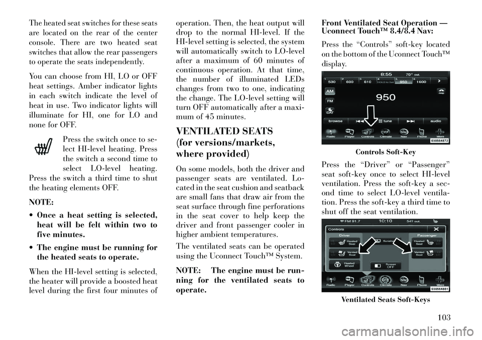
Press the “Controls” soft-key located
on the bottom of the Uconnect Touch™
display.Press the “Driver” or “Passenger”
seat soft-key once to select HI-level
ventilation. Press the soft-key a sec-
ond time to select LO-level ventila-
tion. Press the soft-key a third time to
shut off the seat ventilation.
Controls Soft-Key
Ventilated Seats Soft-Keys
103
Page 115 of 336
WARNING!
Be sure the hood is fully latched
before driving your vehicle. If the
hood is not fully latched, it could
open when the vehicle is in motion
and block your vision. Failure to
follow this warning could result in
serious injury or death.
LIGHTS
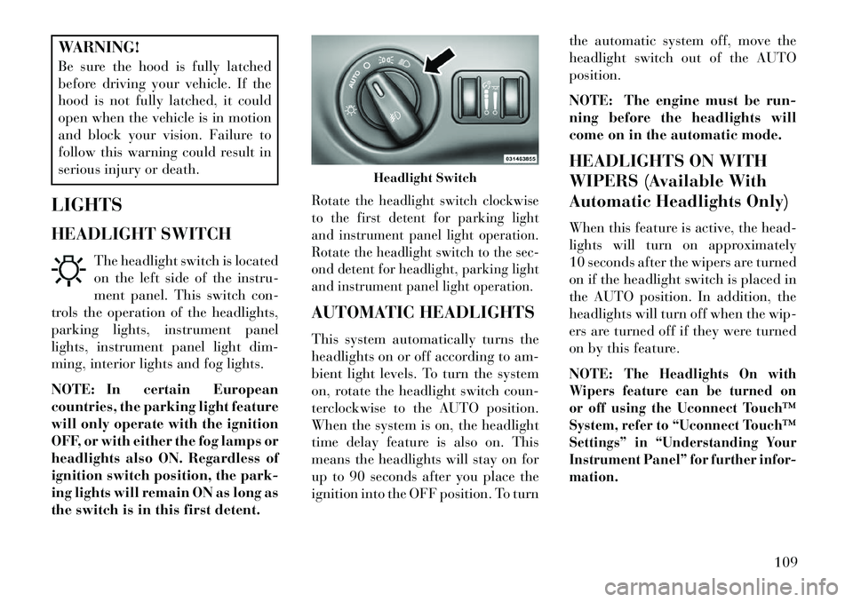
HEADLIGHT SWITCH The headlight switch is located
on the left side of the instru-
ment panel. This switch con-
trols the operation of the headlights,
parking lights, instrument panel
lights, instrument panel light dim-
ming, interior lights and fog lights.
NOTE: In certain European
countries, the parking light feature
will only operate with the ignition
OFF, or with either the fog lamps or
headlights also ON. Regardless of
ignition switch position, the park-
ing lights will remain ON as long as
the switch is in this first detent.
Rotate the headlight switch clockwise
to the first detent for parking light
and instrument panel light operation.
Rotate the headlight switch to the sec-
ond detent for headlight, parking light
and instrument panel light operation.AUTOMATIC HEADLIGHTS
This system automatically turns the
headlights on or off according to am-
bient light levels. To turn the system
on, rotate the headlight switch coun-
terclockwise to the AUTO position.
When the system is on, the headlight
time delay feature is also on. This
means the headlights will stay on for
up to 90 seconds after you place the
ignition into the OFF position. To turn the automatic system off, move the
headlight switch out of the AUTO
position.
NOTE: The engine must be run-
ning before the headlights will
come on in the automatic mode.
HEADLIGHTS ON WITH
WIPERS (Available With
Automatic Headlights Only)
When this feature is active, the head-
lights will turn on approximately
10 seconds after the wipers are turned
on if the headlight switch is placed in
the AUTO position. In addition, the
headlights will turn off when the wip-
ers are turned off if they were turned
on by this feature.
NOTE:
The Headlights On with
Wipers feature can be turned on
or off using the Uconnect Touch™
System, refer to “Uconnect Touch™
Settings” in “Understanding Your
Instrument Panel” for further infor-
mation.
Headlight Switch
109
Page 120 of 336
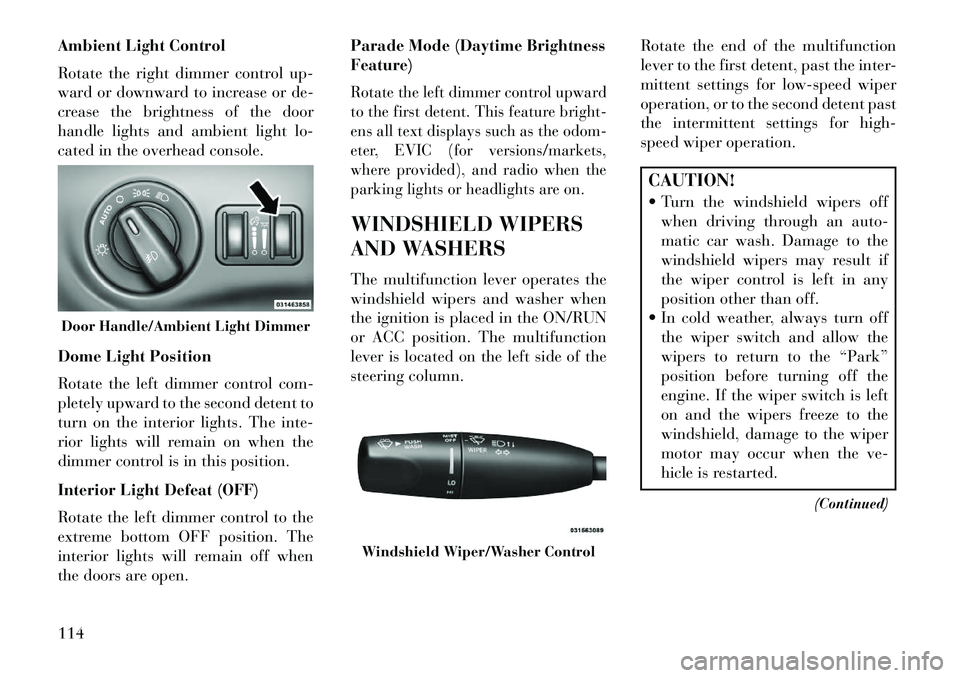
Ambient Light Control
Rotate the right dimmer control up-
ward or downward to increase or de-
crease the brightness of the door
handle lights and ambient light lo-
cated in the overhead console.
Dome Light Position
Rotate the left dimmer control com-
pletely upward to the second detent to
turn on the interior lights. The inte-
rior lights will remain on when the
dimmer control is in this position.
Interior Light Defeat (OFF)
Rotate the left dimmer control to the
extreme bottom OFF position. The
interior lights will remain off when
the doors are open.Parade Mode (Daytime Brightness
Feature)
Rotate the left dimmer control upward
to the first detent. This feature bright-
ens all text displays such as the odom-
eter, EVIC (for versions/markets,
where provided), and radio when the
parking lights or headlights are on.WINDSHIELD WIPERS
AND WASHERS
The multifunction lever operates the
windshield wipers and washer when
the ignition is placed in the ON/RUN
or ACC position. The multifunction
lever is located on the left side of the
steering column.
Rotate the end of the multifunction
lever to the first detent, past the inter-
mittent settings for low-speed wiper
operation, or to the second detent past
the intermittent settings for high-
speed wiper operation.
CAUTION!
Turn the windshield wipers off
when driving through an auto-
matic car wash. Damage to the
windshield wipers may result if
the wiper control is left in any
position other than off.
In cold weather, always turn off the wiper switch and allow the
wipers to return to the “Park”
position before turning off the
engine. If the wiper switch is left
on and the wipers freeze to the
windshield, damage to the wiper
motor may occur when the ve-
hicle is restarted.
(Continued)
Door Handle/Ambient Light Dimmer
Windshield Wiper/Washer Control
114
Page 124 of 336
WARNING!
Do not adjust the steering column
while driving. Adjusting the steer-
ing column while driving or driving
with the steering column unlocked,
could cause the driver to lose con-
trol of the vehicle. Failure to follow
this warning may result in serious
injury or death.
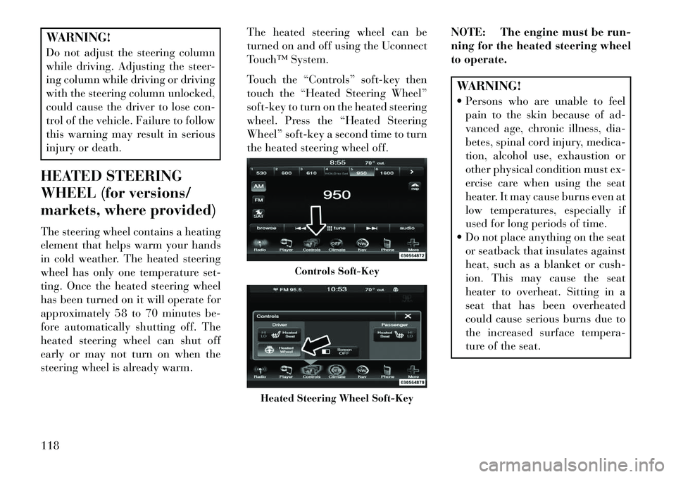
HEATED STEERING
WHEEL (for versions/
markets, where provided)
The steering wheel contains a heating
element that helps warm your hands
in cold weather. The heated steering
wheel has only one temperature set-
ting. Once the heated steering wheel
has been turned on it will operate for
approximately 58 to 70 minutes be-
fore automatically shutting off. The
heated steering wheel can shut off
early or may not turn on when the
steering wheel is already warm. The heated steering wheel can be
turned on and off using the Uconnect
Touch™ System.
Touch the “Controls” soft-key then
touch the “Heated Steering Wheel”
soft-key to turn on the heated steering
wheel. Press the “Heated Steering
Wheel” soft-key a second time to turn
the heated steering wheel off.
NOTE: The engine must be run-
ning for the heated steering wheel
to operate.
WARNING!
Persons who are unable to feel
pain to the skin because of ad-
vanced age, chronic illness, dia-
betes, spinal cord injury, medica-
tion, alcohol use, exhaustion or
other physical condition must ex-
ercise care when using the seat
heater. It may cause burns even at
low temperatures, especially if
used for long periods of time.
Do not place anything on the seat or seatback that insulates against
heat, such as a blanket or cush-
ion. This may cause the seat
heater to overheat. Sitting in a
seat that has been overheated
could cause serious burns due to
the increased surface tempera-
ture of the seat.
Controls Soft-Key
Heated Steering Wheel Soft-Key
118
Page 127 of 336

Pressing the RES (+) button once will
result in the following set speeds:
2.0 km/h (3.0L Diesel Engine)
1.6 km/h (3.6L Engine)
Each subsequent tap of the button
results in an increase of 2.0 km/h
(3.0L Diesel Engine) or 1.6 km/h
(3.6L Engine).
To decrease speed while the Elec-
tronic Speed Control is set, push the
SET (-) button. If the button is con-
tinually held in the SET (-) position,
the set speed will continue to decrease
until the button is released. Release
the button when the desired speed is
reached, and the new set speed will be
established.
Pressing the SET (-) button once will
result in the following decrease in set
speed:
2.0 km/h (3.0L Diesel Engine)
1.6 km/h (3.6L Engine)
Each subsequent tap of the button
results in a decrease of 2.0 km/h
(3.0L Diesel Engine) or 1.6 km/h
(3.6L Engine)TO ACCELERATE FOR
PASSING
Press the accelerator as you would
normally. When the pedal is released,
the vehicle will return to the set speed.
Using Electronic Speed Control
On Hills
The transmission may downshift on
hills to maintain the vehicle set speed.
NOTE:
The Electronic Speed
Control system maintains speed up
and down hills. A slight speed
change on moderate hills is normal.
On steep hills, a greater speed loss or
gain may occur so it may be prefer-
able to drive without Electronic Speed
Control.WARNING!
Electronic Speed Control can be
dangerous where the system cannot
maintain a constant speed. Your ve-
hicle could go too fast for the con-
ditions, and you could lose control
and have an accident. Do not use
(Continued)
WARNING!(Continued)
Electronic Speed Control in heavy
traffic or on roads that are winding,
icy, snow-covered or slippery.
ADAPTIVE CRUISE
CONTROL (ACC)
(for versions/markets,
where provided)
Adaptive Cruise Control (ACC) in-
creases the driving convenience pro-
vided by cruise control while traveling
on highways and major roadways.
However, it is not a safety system and
not designed to prevent collisions.ACC will allow you to keep cruise con-
trol engaged in light to moderate traffic
conditions without the constant need to
reset your cruise control. ACC utilizes a
radar sensor designed to detect a ve-
hicle directly ahead of you.NOTE:
If the sensor does not detect a vehicle ahead of you, ACC will
maintain a fixed set speed.
121
Page 132 of 336

While in US Mode, pressing the SET-
button once will result in a 1.6 km/h
decrease in set speed. Each sub-
sequent tap of the button results in
decrease of 1.6 km/h.
While in Metric Mode, pressing the
SET -button once will result in a
1.0 km/h decrease in set speed. Each
subsequent tap of the button results in
decrease of 1.0 km/h.
NOTE:
When you use the SET - button to decelerate, if the engine’s
braking power does not slow the
vehicle sufficiently to reach the
set speed, the brake system will
automatically slow the vehicle.
The ACC system can only apply a maximum of 25% of the vehi-
cle's braking capability and will
not bring the vehicle to a com-
plete stop.
The ACC system maintains set speed when driving up hill and
down hill. However, a slight
speed change on moderate hills is normal. In addition, down-
shifting may occur while climb-
ing uphill or descending down-
hill. This is normal operation
and necessary to maintain set
speed.
SETTING THE FOLLOWING
DISTANCE IN ACCThe specified following distance for
ACC can be set by varying the dis-
tance setting between 3 (long), 2 (me-
dium), and 1 (short). Using this dis-
tance setting and the vehicle speed,
ACC calculates and sets the distance
to the vehicle ahead. This distance
setting displays in the EVIC.
To change the distance setting, press
the Distance button and release. Each
time the button is pressed, the distance
setting adjusts between 3 (long),
2 (medium), and 1 (short).If there is no vehicle ahead, the vehicle
will maintain the set speed. If a slower
moving vehicle is detected in the same
lane, the EVIC displays the “Sensed
Distance Set 3 (long)
Distance Set 2 (medium)Distance Set 1 (short)
126
Page 152 of 336

The center console outlet is powered
directly from the battery (power
available at all times). Items plugged
into this outlet may discharge the
battery and/or prevent the engine
from starting.
There is also a 12 volt power outlet
located on the back of the center con-
sole for rear passengers. This power
outlet has power available only when
the ignition is placed in the ACC or
RUN position.
WARNING!
To avoid serious injury or death:
Only devices designed for use inthis type of outlet should be in-
serted into any 12 Volt outlet.
Do not touch with wet hands.
Close the lid when not in use and while driving the vehicle.
If this outlet is mishandled, it may cause an electric shock and fail-
ure.
CAUTION!
Many accessories that can beplugged in draw power from the
vehicle's battery even when not in
use (i.e., cellular phones, etc.).
Eventually, if plugged in long
enough, the vehicle's battery will
discharge sufficiently to degrade
battery life and/or prevent the
engine from starting.
Accessories that draw higher
power (i.e., coolers, vacuum
cleaners, lights, etc.) will degrade
the battery even more quickly.
Only use these intermittently and
with greater caution.
After the use of high power draw accessories or long periods of the
vehicle not being started (with
accessories still plugged in), the
vehicle must be driven a suffi-
cient length of time to allow the
alternator to recharge the vehi-
cle's battery.
(Continued)
Center Console Power Outlet
Rear Center Console Power Outlet
Power Outlet Fuse Locations
1 — #12 Fuse 20 A Yellow Cigar
Lighter Instrument Panel And Power
Outlet Console Rear
2 — #38 Fuse 20 A Yellow Power
Outlet Inside Arm Rest
146