run flat Lancia Thema 2013 Owner handbook (in English)
[x] Cancel search | Manufacturer: LANCIA, Model Year: 2013, Model line: Thema, Model: Lancia Thema 2013Pages: 336, PDF Size: 3.87 MB
Page 25 of 336
Turn Headlights On With Remote
Key UnlockThis feature activates the headlights
for up to 90 seconds when the doors
are unlocked with the RKE trans-
mitter. The time for this feature is
programmable on vehicles equipped
through Uconnect Touch™. To change
the current setting, refer to “Uconnect
Touch™ Settings” in “Understanding
Your Instrument Panel” for further in-
formation.TO LOCK THE DOORS
Press and release the LOCK button on
the RKE transmitter to lock all doors.
The turn signal lights will flash to
acknowledge the signal.If the vehicle is equipped with Passive
Entry, refer to “Keyless Enter-N-Go”
under “Things To Know Before Starting
Your Vehicle” for further information.TO UNLATCH THE TRUNK
Press the TRUNK button on the RKE
transmitter two times within five sec-
onds to unlatch the trunk.
If the vehicle is equipped with Passive
Entry, refer to “Keyless Enter-N-Go”
under “Things To Know Before Starting
Your Vehicle” for further information.TRANSMITTER BATTERY
REPLACEMENT
The recommended replacement bat-
tery is one CR2032 battery.
NOTE:
Perchlorate Material — specialhandling may apply. Batteries
could contain dangerous mate-
rials. Please dispose of them ac-
cording to respect for environ-
ment and local laws.
Do not touch the battery termi- nals that are on the back hous-
ing or the printed circuit board.
1. Remove the emergency key by
sliding the mechanical latch on the
back of the RKE transmitter sideways
with your thumb and then pull the
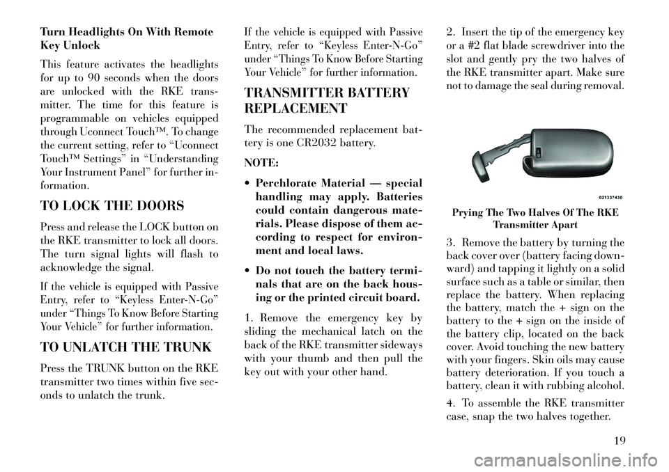
key out with your other hand. 2.
Insert the tip of the emergency key
or a #2 flat blade screwdriver into the
slot and gently pry the two halves of
the RKE transmitter apart. Make sure
not to damage the seal during removal.
3. Remove the battery by turning the
back cover over (battery facing down-
ward) and tapping it lightly on a solid
surface such as a table or similar, then
replace the battery. When replacing
the battery, match the + sign on the
battery to the + sign on the inside of
the battery clip, located on the back
cover. Avoid touching the new battery
with your fingers. Skin oils may cause
battery deterioration. If you touch a
battery, clean it with rubbing alcohol.
4. To assemble the RKE transmitter
case, snap the two halves together.Prying The Two Halves Of The RKE Transmitter Apart
19
Page 33 of 336
With the ignition in the ON/RUN po-
sition, the Trunk Open symbol will
display in the instrument cluster indi-
cating that the trunk is open. The
odometer display will reappear once
the trunk is closed.
With the ignition in the OFF position,
the Trunk Open symbol will display
until the trunk is closed.
Refer to “Keyless EnterNGo™” in
“Things To Know Before Starting
Your Vehicle” for more information
on trunk operation with the Passive
Entry feature.
TRUNK SAFETY
WARNINGWARNING!Do not allow children to have access
to the trunk, either by climbing into
the trunk from outside, or through
the inside of the vehicle. Always
close the trunk lid when your vehicle
is unattended. Once in the trunk,
young children may not be able to
(Continued)
WARNING!(Continued)escape, even if they entered through
the rear seat. If trapped in the trunk,
children can die from suffocation or
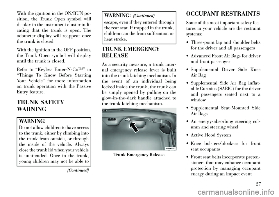
heat stroke.TRUNK EMERGENCY
RELEASE
As a security measure, a trunk inter-
nal emergency release lever is built
into the trunk latching mechanism. In
the event of an individual being
locked inside the trunk, the trunk can
be simply opened by pulling on the
glow-in-the-dark handle attached to
the trunk latching mechanism. OCCUPANT RESTRAINTS
Some of the most important safety fea-
tures in your vehicle are the restraint
systems: Three-point lap and shoulder belts
for the driver and all passengers
Advanced Front Air Bags for driver and front passenger
Supplemental Driver Side Knee Air Bag
Supplemental Side Air Bag Inflat-
able Curtains (SABIC) for the driver
and passengers seated next to a
window Supplemental Seat-Mounted Side Air Bags
An energy-absorbing steering col- umn and steering wheel
Active Hood System
Knee bolsters/blockers for front seat occupants
Front seat belts incorporate preten- sioners that may enhance occupant
protection by managing occupant
energy during an impact event
Trunk Emergency Release
27
Page 47 of 336

Air Bag Deployment Sensors
And Controls
Occupant Restraint Controller
(ORC)
The ORC is part of a regulated safety
system required for this vehicle.
The ORC determines if deployment of
the front and/or side air bags in a
frontal or side collision is required.
Based on the impact sensor's signals,
a central electronic ORC deploys the
Advanced Front Air Bags, SABIC air
bags, SAB, Supplemental Driver Side
Knee Air Bag, and front seat belt pre-
tensioners, as required, depending on
several factors, including the severity
and type of impact.
Advanced Front Air Bags and Supple-
mental Driver Side Knee Air Bag are
designed to provide additional protec-
tion by supplementing the seat belts
in certain frontal collisions depending
on several factors, including the se-
verity and type of collision. Advanced
Front Air Bags are not expected to
reduce the risk of injury in rear, side,
or rollover collisions.The Advanced Front Air Bags and
Supplemental Driver Side Knee Air
Bag will not deploy in all frontal col-
lisions, including some that may pro-
duce substantial vehicle damage —
for example, some pole collisions,
truck underrides, and angle offset col-
lisions. On the other hand, depending
on the type and location of impact,
Advanced Front Air Bags may deploy
in crashes with little vehicle front-end
damage but that produce a severe ini-
tial deceleration.
The side air bags will not deploy in all
side collisions. Side air bag deploy-
ment will depend on the severity and
type of collision.
Because air bag sensors measure ve-
hicle deceleration over time, vehicle
speed and damage by themselves are
not good indicators of whether or not
an air bag should have deployed.
Seat belts are necessary for your pro-
tection in all collisions, and also are
needed to help keep you in position,
away from an inflating air bag.
The ORC monitors the readiness of
the electronic parts of the air bag sys-
tem whenever the ignition is in the
START or ON/RUN position. If the
ignition is in the OFF position or in
the ACC position, the air bag system
is not on and the air bags will not
inflate.
The ORC contains a backup power
supply system that may deploy the air
bags even if the battery loses power
or it becomes disconnected prior to
deployment.
Also, the ORC turns on the
Air Bag Warning Light in the
instrument panel for ap-
proximately four to eight sec-
onds for a self-check when the
ignition is first turned on. After the self-
check, the Air Bag Warning Light will
turn off. If the ORC detects a malfunc-
tion in any part of the system, it turns on
the Air Bag Warning Light, either mo-
mentarily or continuously. A single
chime will sound if the light comes on
again after initial startup.
41
Page 50 of 336
If you do have a collision, which de-
ploys the air bags, any or all of the
following may occur:
The nylon air bag material maysometimes cause abrasions and/or
skin reddening to the driver and
front passenger as the air bags de-
ploy and unfold. The abrasions are
similar to friction rope burns or
those you might get sliding along a
carpet or gymnasium floor. They
are not caused by contact with
chemicals. They are not permanent
and normally heal quickly. How-
ever, if you haven't healed signifi-
cantly within a few days, or if you
have any blistering, see your doctor
immediately.
As the air bags deflate, you may see
some smoke-like particles. The par-
ticles are a normal by-product of the
process that generates the non-toxic
gas used for air bag inflation. These
airborne particles may irritate the
skin, eyes, nose, or throat. If you
have skin or eye irritation, rinse the area with cool water. For nose or
throat irritation, move to fresh air.
If the irritation continues, see your
doctor. If these particles settle on
your clothing, follow the garment
manufacturer's instructions for
cleaning.
Do not drive your vehicle after the air
bags have deployed. If you are in-
volved in another collision, the air bags
will not be in place to protect you.
WARNING!
Deployed air bags and seat belt
pretensioners cannot protect you in
another collision. Have the air
bags, seat belt pretensioners, and
the front seat belt retractor assem-
blies replaced by an authorized
dealer immediately. Also, have the
Occupant Restraint Controller Sys-
tem serviced as well. Maintaining Your Air Bag System
WARNING!
Modifications to any part of the
air bag system could cause it to
fail when you need it. You could
be injured if the air bag system is
not there to protect you. Do not
modify the components or wiring,
including adding any kind of
badges or stickers to the steering
wheel hub trim cover or the upper
right side of the instrument panel.
Do not modify the front bumper,
vehicle body structure, or add af-
termarket side steps or running
boards.
It is dangerous to try to repair any
part of the air bag system your-
self. Be sure to tell anyone who
works on your vehicle that it has
an air bag system.
(Continued)
44
Page 51 of 336
WARNING!(Continued)
Do not attempt to modify any part
of your air bag system. The air bag
may inflate accidentally or may
not function properly if modifica-
tions are made. Take your vehicle
to an authorized dealer for any
air bag system service. If your seat,
including your trim cover and
cushion, needs to be serviced in
any way (including removal or
loosening/tightening of seat at-
tachment bolts), take the vehicle
to your authorized dealer. Only
manufacturer approved seat ac-
cessories may be used. If it is nec-
essary to modify the air bag system
for persons with disabilities, con-
tact your authorized dealer.
Air Bag Warning Light
You will want to have the
air bags ready to inflate for
your protection in a colli-
sion. The Air Bag Warning
Light monitors the internal circuits
and interconnecting wiring associated with air bag system electrical compo-
nents. While the air bag system is
designed to be maintenance free. If
any of the following occurs, have an
authorized dealer service the air bag
system immediately.
The Air Bag Warning Light does
not come on during the four to eight
seconds when the ignition is first
cycled to the ON/RUN.
The Air Bag Warning Light remains on after the four to eight-second
interval.
The Air Bag Warning Light comes on intermittently or remains on
while driving.
NOTE:
If the speedometer, ta-
chometer, or any engine related
gauges are not working, the Occu-
pant Restraint Controller (ORC)
may also be disabled. The air bags
may not be ready to inflate for your
protection. Promptly check the fuse
block for blown fuses. Refer to the
label located on the inside of the
fuse block cover for the proper air
bag fuses. See your authorized
dealer if the fuse is good.
Event Data Recorder (EDR)This vehicle is equipped with an event
data recorder (EDR). The main pur-
pose of an EDR is to record, in certain
crash or near crash-like situations,
such as an air bag deployment or hit-
ting a road obstacle, data that will
assist in understanding how a vehicle’s
systems performed. The EDR is de-
signed to record data related to vehicle
dynamics and safety systems for a
short period of time, typically 30 sec-
onds or less. The EDR in this vehicle is
designed to record such data as: How various systems in your ve-
hicle were operating;
Whether or not the driver and pas- senger safety belts were
buckled/fastened;
How far (if at all) the driver was depressing the accelerator and/or
brake pedal; and,
How fast the vehicle was traveling.
These data can help provide a better
understanding of the circumstances in
which crashes and injuries occur.
45
Page 165 of 336
vehicle manufacturer on the vehicle
placard or tire inflation pressure
label.
As an added safety feature, your ve-
hicle has been equipped with a Tire
Pressure Monitoring System (TPMS)
that illuminates a low tire pressure
telltale when one or more of your tires
is significantly under-inflated. Ac-
cordingly, when the low tire pressure
telltale illuminates, you should stop
and check your tires as soon as pos-
sible, and inflate them to the proper
pressure. Driving on a significantly
under-inflated tire causes the tire to
overheat and can lead to tire failure.
Under-inflation also reduces fuel effi-
ciency and tire tread life, and may
affect the vehicle’s handling and stop-
ping ability.
Please note that the TPMS is not a
substitute for proper tire mainte-
nance, and it is the driver’s responsi-
bility to maintain correct tire pres-
sure, even if under-inflation has not
reached the level to trigger illumina-
tion of the TPMS low tire pressure
telltale.Your vehicle has also been equipped
with a TPMS malfunction indicator to
indicate when the system is not oper-
ating properly. The TPMS malfunc-
tion indicator is combined with the
low tire pressure telltale. When the
system detects a malfunction, the tell-
tale will flash for approximately one
minute and then remain continuously
illuminated. This sequence will con-
tinue upon subsequent vehicle start-
ups as long as the malfunction exists.
When the malfunction indicator is il-
luminated, the system may not be
able to detect or signal low tire pres-
sure as intended. TPMS malfunctions
may occur for a variety of reasons,
including the installation of replace-
ment or alternate tires or wheels on
the vehicle that prevent the TPMS
from functioning properly. Always
check the TPMS malfunction telltale
after replacing one or more tires or
wheels on your vehicle, to ensure that
the replacement or alternate tires and
wheels allow the TPMS to continue to
function properly.
CAUTION!
The TPMS has been optimized for
the original equipment tires and
wheels. TPMS pressures and warn-
ing have been established for the
tire size equipped on your vehicle.
Undesirable system operation or
sensor damage may result when us-
ing replacement equipment that is
not of the same size, type, and/or
style. Aftermarket wheels can cause
sensor damage. Do not use tire seal-
ant from a can or balance beads if
your vehicle is equipped with a
TPMS, as damage to the sensors
may result.
9. Malfunction Indicator
Light (MIL) The Malfunction Indicator
Light (MIL) is part of an on-
board diagnostic system,
called OBD, that monitors engine and
automatic transmission control sys-
tems. The light will illuminate when
the key is in the ON/RUN position,
before engine start. If the bulb does
not come on when turning the key
from OFF to ON/RUN, have the con-
dition checked promptly.
159
Page 217 of 336

TRACTION
When driving on wet or slushy roads,
it is possible for a wedge of water to
build up between the tire and road
surface. This is known as hydroplan-
ing and may cause partial or complete
loss of vehicle control and stopping
ability. To reduce this possibility, the
following precautions should be ob-
served:
1. Slow down during rainstorms or
when the roads are slushy.
2. Slow down if the road has standing
water or puddles.
3. Replace tires when tread wear in-
dicators first become visible.
4. Keep tires properly inflated.
5. Maintain sufficient distance be-
tween your vehicle and the vehicle in
front of you to avoid a collision in a
sudden stop.DRIVING THROUGH
WATER
Driving through water more than a
centimeters deep will require extra
caution to ensure safety and prevent
damage to your vehicle.
FLOWING/RISING WATER
WARNING!
Do not drive on or across a road or
path where water is flowing and/or
rising (as in storm run-off). Flow-
ing water can wear away the road
or path's surface and cause your
vehicle to sink into deeper water.
Furthermore, flowing and/or rising
water can carry your vehicle away
swiftly. Failure to follow this warn-
ing may result in injuries that are
serious or fatal to you, your passen-
gers, and others around you.
SHALLOW STANDING
WATER
Although your vehicle is capable of
driving through shallow standing wa-
ter, consider the following Caution
and Warning before doing so.
CAUTION!
Always check the depth of the
standing water before driving
through it. Never drive through
standing water that is deeper than
the bottom of the tire rims mounted
on the vehicle.
Determine the condition of the road
or the path that is under water and
if there are any obstacles in the way
before driving through the standing
water.
Do not exceed 8 km/h when driving
through standing water. This will
minimize wave effects.
(Continued)
211
Page 221 of 336
The Electronic Brake Force Distribu-
tion (EBD) prevents the rear wheels
from over-braking and provides
greater control of available braking
forces applied to the rear axle.
When the vehicle is driven over
11 km/h, you may also hear a slight
clicking sound as well as some related
motor noises. These noises are the sys-
tem performing its self check cycle to
ensure that the ABS is working prop-
erly. This self check occurs each time
the vehicle is started and accelerated
past 11 km/h.
ABS is activated during braking un-
der certain road or stopping condi-
tions. ABS-inducing conditions can
include ice, snow, gravel, bumps, rail-
road tracks, loose debris, or panic
stops.
You also may experience the following
when the brake system goes into Anti-
Lock:
The ABS motor running (it maycontinue to run for a short time
after the stop), The clicking sound of solenoid
valves,
Brake pedal pulsations, and
A slight drop or fall away of the brake pedal at the end of the stop.
These are all normal characteristics of
ABS.
WARNING!
The ABS contains sophisticated electronic equipment that may be
susceptible to interference caused
by improperly installed or high
output radio transmitting equip-
ment. This interference can cause
possible loss of anti-lock braking
capability. Installation of such
equipment should be performed
by qualified professionals.
Pumping of the Anti-Lock Brakes will diminish their effectiveness
and may lead to a collision.
Pumping makes the stopping dis-
tance longer. Just press firmly on
your brake pedal when you need
to slow down or stop.
(Continued)
WARNING!(Continued)
The ABS cannot prevent the natu-
ral laws of physics from acting on
the vehicle, nor can it increase
braking or steering efficiency be-
yond that afforded by the condi-
tion of the vehicle brakes and tires
or the traction afforded. The ABS cannot prevent colli- sions, including those resulting
from excessive speed in turns,
following another vehicle too
closely, or hydroplaning.
The capabilities of an ABS
equipped vehicle must never be
exploited in a reckless or danger-
ous manner that could jeopardize
the user's safety or the safety of
others.
All vehicle wheels and tires must be
the same size and type and tires must
be properly inflated to produce accu-
rate signals for the computer.
215
Page 261 of 336

TIREFIT KIT
(for versions/markets,
where provided)
Small punctures up to 6 mm in the tire
tread can be sealed with TIREFIT.
Foreign objects (e.g., screws or nails)
should not be removed from the tire.
TIREFIT can be used in outside tem-
peratures down to approximately
20°C.
This kit will provide a temporary tire
seal, allowing you to drive your ve-
hicle up to 160 km with a maximum
speed of 88 km/h.
TIREFIT STORAGE
The TIREFIT kit is located in the
trunk.TIREFIT KIT
COMPONENTS AND
OPERATION
1. Sealant Bottle
2. Deflation Button
3. Pressure Gauge
4. Power Button
5. Mode Select Knob
6. Sealant Hose (Clear)
7. Air Pump Hose (Black)
8. Power PlugUsing The Mode Select Knob And
Hoses
Your TIREFIT kit is equipped with
the following symbols to indicate the
air or sealant mode.
Selecting Air Mode
Turn the Mode Select
Knob (5) to this position for
air pump operation only.
Use the Black Air Pump
Hose (7) when selecting this mode.
Selecting Sealant Mode
Turn the Mode Se-
lect Knob (5) to
this position to in-
ject the TIREFIT
Sealant and to in-
flate the tire. Use
the Sealant Hose
(clear hose) (6) when selecting this
mode.
TIREFIT Location
255
Page 263 of 336
WARNING!(Continued)
A loose TIREFIT kit thrown for- ward in a collision or hard stop
could endanger the occupants of
the vehicle. Always stow the
TIREFIT kit in the place pro-
vided. Failure to follow these
warnings can result in injuries
that are serious or fatal to you,
your passengers, and others
around you.
Take care not to allow the con- tents of TIREFIT to come in con-
tact with hair, eyes, or clothing.
TIREFIT is harmful if inhaled,
swallowed, or absorbed through
the skin: It causes skin, eye, and
respiratory irritation. Flush im-
mediately with plenty of water if
there is any contact with eyes or
skin. Change clothing as soon as
possible, if there is any contact
with clothing.
(Continued)
WARNING!(Continued)
TIREFIT Sealant solution con- tains latex. In case of allergic re-
action or rash, consult a physi-
cian immediately. Keep TIREFIT
out of reach of children. If swal-
lowed, rinse mouth immediately
with plenty of water and drink
plenty of water. Do not induce
vomiting! Consult a physician
immediately.
Use the gloves provided in the Accessory Storage Compartment
(located on the bottom of the air
pump) when operating the TIRE-
FIT kit.
SEALING A TIRE WITH
TIREFIT
(A) Whenever You Stop To Use
TIREFIT:
1. Pull over to a safe location and
turn on the vehicle’s Hazard Warning
flashers. 2.
Verify that the valve stem (on the
wheel with the deflated tire) is in a
position that is near to the ground. This
will allow the TIREFIT Hoses (6) and
(7) to reach the valve stem and keep the
TIREFIT kit flat on the ground. This
will provide the best positioning of the
kit when injecting the sealant into the
deflated tire and running the air pump.
Move the vehicle as necessary to place
the valve stem in this position before
proceeding.
3.
Place the transmission in PARK
(auto transmission) or in Gear (manual
transmission) and turn Off the ignition.
4. Set the parking brake.
(B) Setting Up To Use TIREFIT:
1. Turn the Mode Select Knob (5) to
the Sealant Mode position.
2. Uncoil the Sealant Hose (6) and
then remove the cap from the fitting
at the end of the hose.
3. Place the TIREFIT kit flat on the
ground next to the deflated tire.
257