trunk Lancia Thema 2014 Owner handbook (in English)
[x] Cancel search | Manufacturer: LANCIA, Model Year: 2014, Model line: Thema, Model: Lancia Thema 2014Pages: 332, PDF Size: 3.46 MB
Page 75 of 332

CUPHOLDERS..........................149
FRONT SEAT CUPHOLDERS ..............149
REAR SEAT CUPHOLDERS ...............150
STORAGE ...............................150
GLOVEBOX STORAGE ...................150
CONSOLE FEATURES ...................150
DOOR STORAGE .......................151
REAR SEAT ARMREST STORAGE (for versions/markets, where provided) ..........151
CARGO AREA — VEHICLES EQUIPPED WITH 60/40 SPLIT-FOLDING REAR SEAT .........151
CARGO AREA FEATURES ..................152
TRUNK MAT (for versions/markets, where provided) .............................152
GROCERY BAG HOOKS (for versions/markets where provided) .......................153
CARGO NET (for versions/markets where provided) .............................153
REAR WINDOW FEATURES ................153
REAR WINDOW DEFROSTER .............153
POWER SUNSHADE (for versions/markets, where provided) ........................153
LOAD LEVELING SYSTEM ................154
69
Page 123 of 332

To protect the battery, the interior
lights will turn off automatically 10
minutes after the ignition switch is
moved to the LOCK position. This
will occur if the interior lights were
switched on manually or are on be-
cause a door is open. This includes the
glove box light, but not the trunk
light. To restore interior light opera-
tion, either turn the ignition switch
ON or cycle the light switch.
Dimmer Controls
The dimmer control is part of the
headlight switch and is located on the
left side of the instrument panel.
With the parking lights or headlights
on, rotating the left dimmer controlupward will increase the brightness of
the instrument panel lights and
lighted cupholders.
Ambient Light Control
Rotate the right dimmer control up-
ward or downward to increase or de-
crease the brightness of the door
handle lights and ambient light lo-
cated in the overhead console.
Dome Light Position
Rotate the left dimmer control com-
pletely upward to the second detent to
turn on the interior lights. The inte-
rior lights will remain on when the
dimmer control is in this position.
Interior Light Defeat (OFF)
Rotate the left dimmer control to the
extreme bottom OFF position. The
interior lights will remain off when
the doors are open.
Parade Mode (Daytime Brightness
Feature)
Rotate the left dimmer control up-
ward to the first detent. This feature
brightens all text displays such as the
odometer, EVIC (for versions/
markets, where provided), and radio
when the parking lights or headlights
are on.
WINDSHIELD WIPERS
AND WASHERS
The multifunction lever operates the
windshield wipers and washer when
the ignition is placed in the ON/RUN
Dimmer Controls
Instrument Panel Dimmer
Door Handle/Ambient Light Dimmer
117
Page 158 of 332

down, they provide a continuous,
nearly-flat extension of the load floor.
When the seatback is folded to the
upright position, make sure it is
latched by strongly pulling on the top
of the seatback above the seat strap.
WARNING!
Be certain that the seatback issecurely locked into position. If
the seatback is not securely
locked into position, the seat will
not provide the proper stability
for child seats and/or passengers.
An improperly latched seat could
cause serious injury.
The cargo area in the rear of the vehicle (with the rear seatbacks
in the locked-up or folded down
position) should not be used as a
play area by children when the
vehicle is in motion. They could
be seriously injured in a collision.
Children should be seated and us-
ing the proper restraint system.
(Continued)
WARNING!(Continued)
To help protect against personalinjury, passengers should not be
seated in the rear cargo area. The
rear cargo space is intended for
load carrying purposes only, not
for passengers, who should sit in
seats and use seat belts.
WARNING!
The weight and position of cargo
and passengers can change the ve-
hicle center of gravity and vehicle
handling. To avoid loss of control
resulting in personal injury, follow
these guidelines for loading your
vehicle:
Always place cargo evenly on thecargo floor. Put heavier objects as
low and as far forward as pos-
sible.
(Continued)
WARNING!(Continued)
Place as much cargo as possible infront of the rear axle. Too much
weight or improperly placed
weight over or behind the rear
axle can cause the rear of the ve-
hicle to sway.
Do not pile luggage or cargo higher than the top of the seat-
back. This could impair visibility
or become a dangerous projectile
in a sudden stop or collision.
CARGO AREA FEATURES
TRUNK MAT (for
versions/markets, where
provided)
A trunk mat covers the bottom of the
cargo area. The trunk mat is used to
protect the interior of the trunk from
mud, snow, and debris.
152
Page 164 of 332

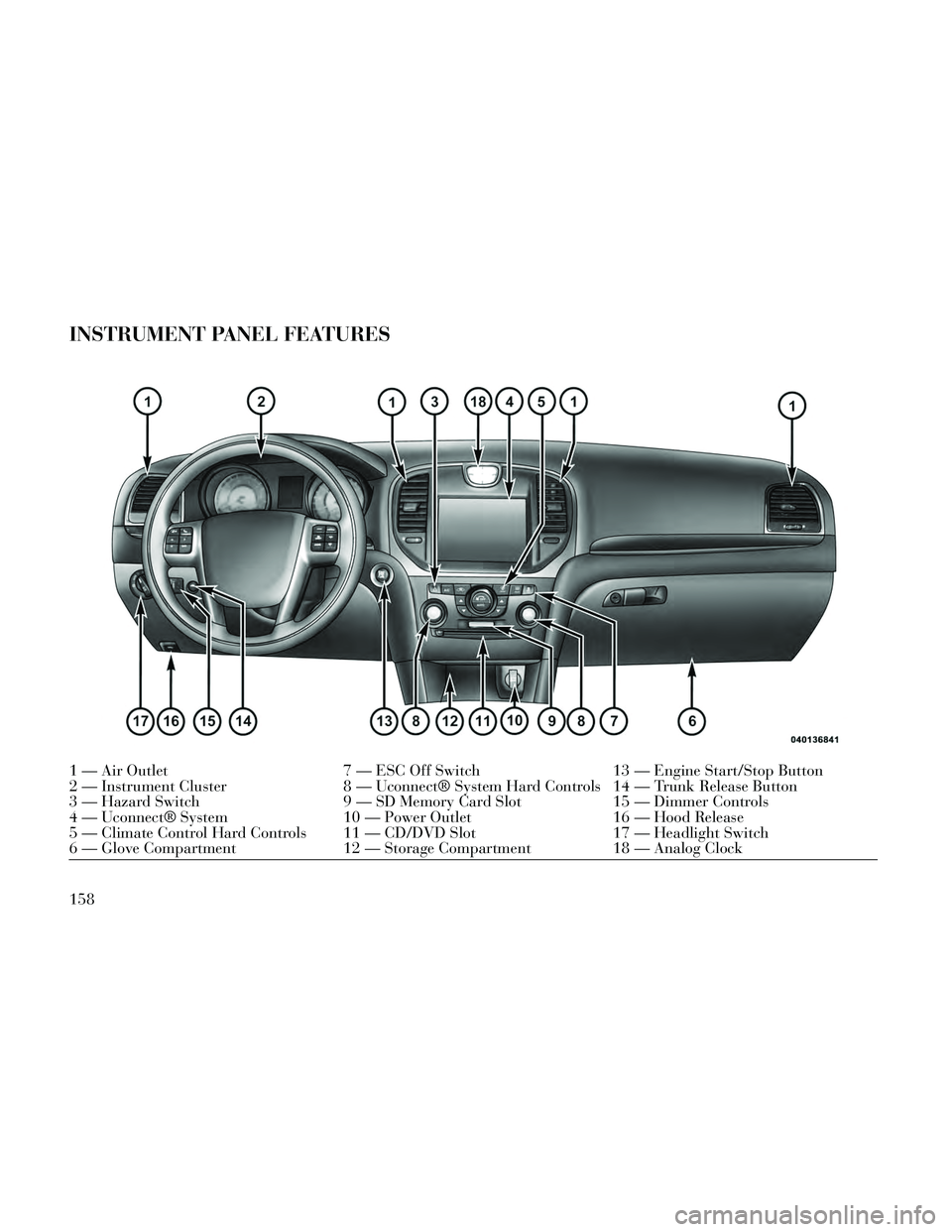
INSTRUMENT PANEL FEATURES
1 — Air Outlet7 — ESC Off Switch13 — Engine Start/Stop Button
2 — Instrument Cluster 8 — Uconnect® System Hard Controls 14 — Trunk Release Button
3 — Hazard Switch 9 — SD Memory Card Slot15 — Dimmer Controls
4 — Uconnect® System 10 — Power Outlet16 — Hood Release
5 — Climate Control Hard Controls 11 — CD/DVD Slot 17 — Headlight Switch
6 — Glove Compartment 12 — Storage Compartment18 — Analog Clock
158
Page 175 of 332

filter to prevent engine damage. Refer
to “Maintenance Procedures/ Drain-
ing Fuel/Water Separator Filter” in
“Maintaining Your Vehicle” for water
drain procedure.
SERV AWD (Service All Wheel
Drive) Indicator (for versions/
markets, where provided)This light will turn on when
the All Wheel Drive feature
requires service. For further
information, refer to “All
Wheel Drive” in “Starting And
Operating.”
EVIC RED TELLTALES
This area will show reconfigurable red
telltales. These telltales include:
Door Ajar
This telltale turns on when
one or more doors are ajar.
The telltale will show which
doors are ajar.
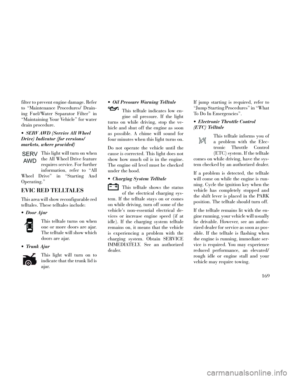
Trunk Ajar
This light will turn on to
indicate that the trunk lid is
ajar. Oil Pressure Warning Telltale
This telltale indicates low en-
gine oil pressure. If the light
turns on while driving, stop the ve-
hicle and shut off the engine as soon
as possible. A chime will sound for
four minutes when this light turns on.
Do not operate the vehicle until the
cause is corrected. This light does not
show how much oil is in the engine.
The engine oil level must be checked
under the hood.
Charging System Telltale
This telltale shows the status
of the electrical charging sys-
tem. If the telltale stays on or comes
on while driving, turn off some of the
vehicle's non-essential electrical de-
vices or increase engine speed (if at
idle). If the charging system telltale
remains on, it means that the vehicle
is experiencing a problem with the
charging system. Obtain SERVICE
IMMEDIATELY. See an authorized
dealer. If jump starting is required, refer to
“Jump Starting Procedures” in “What
To Do In Emergencies”.
Electronic Throttle Control
(ETC) Telltale
This telltale informs you of
a problem with the Elec-
tronic Throttle Control
(ETC) system. If the telltale
comes on while driving, have the sys-
tem checked by an authorized dealer.
If a problem is detected, the telltale
will come on while the engine is run-
ning. Cycle the ignition key when the
vehicle has completely stopped and
the shift lever is placed in the PARK
position. The telltale should turn off.
If the telltale remains lit with the en-
gine running, your vehicle will usually
be drivable. However, see an autho-
rized dealer for service as soon as pos-
sible. If the telltale is flashing when
the engine is running, immediate ser-
vice is required. You may experience
reduced performance, an elevated/
rough idle or engine stall and your
vehicle may require towing.
169
Page 245 of 332

in your area, a high cetane “pre-
mium” diesel fuel may offer improved
cold-starting and warm-up perfor-
mance.
BIODIESEL FUEL
REQUIREMENTS
A maximum blend of 7% biodiesel
meeting the EN590 standard are also
recommended for use with your diesel
engine. See your authorized dealer for
further information regarding fuels
available in your area.
ADDING FUEL
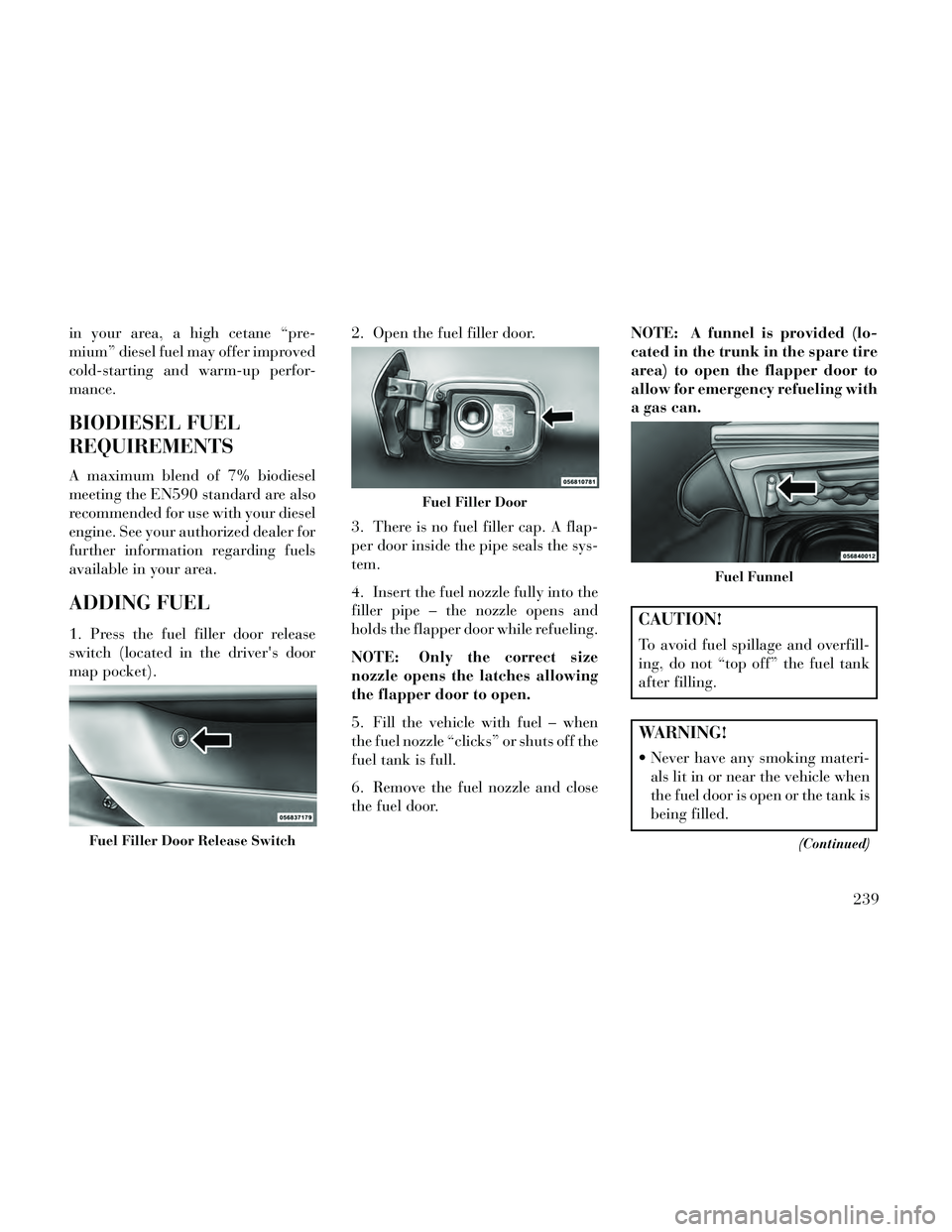
1. Press the fuel filler door release
switch (located in the driver's door
map pocket).2. Open the fuel filler door.
3. There is no fuel filler cap. A flap-
per door inside the pipe seals the sys-
tem.
4. Insert the fuel nozzle fully into the
filler pipe – the nozzle opens and
holds the flapper door while refueling.
NOTE: Only the correct size
nozzle opens the latches allowing
the flapper door to open.
5. Fill the vehicle with fuel – when
the fuel nozzle “clicks” or shuts off the
fuel tank is full.
6. Remove the fuel nozzle and close
the fuel door.NOTE: A funnel is provided (lo-
cated in the trunk in the spare tire
area) to open the flapper door to
allow for emergency refueling with
a gas can.CAUTION!
To avoid fuel spillage and overfill-
ing, do not “top off” the fuel tank
after filling.
WARNING!
Never have any smoking materi-
als lit in or near the vehicle when
the fuel door is open or the tank is
being filled.
(Continued)Fuel Filler Door Release Switch
Fuel Filler Door
Fuel Funnel
239
Page 246 of 332

WARNING!(Continued)
Never add fuel when the engine isrunning. This is in violation of
most state and federal fire regula-
tions and may cause the “Mal-
function Indicator Light” to turn
on.
A fire may result if fuel is pumped into a portable container that is
inside of a vehicle. You could be
burned. Always place fuel con-
tainers on the ground while fill-
ing.
EMERGENCY FUEL
FILLER DOOR RELEASE
If you are unable to open the fuel filler
door, use the fuel filler door emer-
gency release.
1. Open the trunk.
2. Remove the access cover (located
on the left side inner trim panel). 3. Pull the release cable.
TRAILER TOWING
In this section you will find safety tips
and information on limits to the type
of towing you can reasonably do with
your vehicle. Before towing a trailer,
carefully review this information to
tow your load as efficiently and safely
as possible.To maintain the New Vehicle Limited
Warranty coverage, follow the re-
quirements and recommendations in
this manual concerning vehicles used
for trailer towing.
COMMON TOWING
DEFINITIONS
The following trailer towing related
definitions will assist you in under-
standing the following information:
Gross Vehicle Weight Rating
(GVWR)
The GVWR is the total allowable
weight of your vehicle. This includes
driver, passengers, cargo and tongue
weight. The total load must be limited
so that you do not exceed the GVWR.
Refer to “Vehicle Loading/Vehicle
Certification Label” in “Starting and
Operating” for further information.
Gross Trailer Weight (GTW)
The GTW is the weight of the trailer
plus the weight of all cargo, consum-
ables and equipment (permanent or
temporary) loaded in or on the trailerAccess Cover
Release Cable
240
Page 260 of 332

TIREFIT STORAGE
The TIREFIT kit is located in the
trunk.
TIREFIT KIT
COMPONENTS AND
OPERATION
1. Sealant Bottle
2. Deflation Button
3. Pressure Gauge4. Power Button
5. Mode Select Knob
6. Sealant Hose (Clear)
7. Air Pump Hose (Black)
8. Power Plug
Using The Mode Select Knob And
Hoses
Your TIREFIT kit is equipped with
the following symbols to indicate the
air or sealant mode.
Selecting Air Mode
Turn the Mode Select Knob
(5) to this position for air
pump operation only. Use
the Black Air Pump Hose
(7) when selecting this mode.
Selecting Sealant Mode
Turn the Mode Se-
lect Knob (5) to this
position to inject
the TIREFIT Seal-
ant and to inflate
the tire. Use the
Sealant Hose (clear
hose) (6) when selecting this mode.
Using The Power Button
Push and release the Power
Button (4) once to turn On
the TIREFIT kit. Push and
release the Power Button
(4) again to turn Off the TIREFIT kit.
Using The Deflation Button
Press the Deflation Button
(2) to reduce the air pres-
sure in the tire if it becomes
over-inflated.
TIREFIT USAGE
PRECAUTIONS
Using the TIREFIT sealant maycause the Tire Pressure Monitoring
System (TPMS) to become inoper-
able. It is recommended that you
take your vehicle to an authorized
dealer to have the sensor function
checked.
Replace the TIREFIT Sealant Bottle (1) and Sealant Hose (6)
prior to the expiration date (printed
on the bottle label) to assure opti-
mum operation of the system. Refer
TIREFIT Location
254
Page 265 of 332

3. Place the TIREFIT kit in its proper
storage area in the vehicle.
4. Have the tire inspected and re-
paired or replaced at the earliest op-
portunity at an authorized dealer or
tire service center.
5. Replace the Sealant Bottle (1) and
Sealant Hose (6) assembly at your
authorized dealer as soon as possible.
Refer to “(F) Sealant Bottle and Hose
Replacement.”
NOTE: When having the tire ser-
viced, advise the authorized dealer
or service center that the tire has
been sealed using the TIREFIT
service kit.
(F) Sealant Bottle And Hose
Replacement:
1. Uncoil the Sealant Hose (6) (clear
in color).
2. Locate the round Sealant Bottle
release button in the recessed area
under the sealant bottle.3. Press the Sealant Bottle release
button. The Sealant Bottle (1) will
pop up. Remove the bottle and dis-
pose of it accordingly.
4. Clean any remaining sealant from
the TIREFIT housing.
5. Position the new Sealant Bottle (1)
in the housing so that the Sealant
Hose (6) aligns with the hose slot in
the front of the housing. Press the
bottle into the housing. An audible
click will be heard indicating the
bottle is locked into place.
6. Verify that the cap is installed on
the fitting at the end of the Sealant
Hose (6) and return the hose to its
storage area (located on the bottom of
the air pump).
7. Return the TIREFIT kit to its stor-
age location in the vehicle.
JUMP-STARTING
PROCEDURES
If your vehicle has a discharged bat-
tery it can be jump-started using a set
of jumper cables and a battery in an-
other vehicle or by using a portablebattery booster pack. Jump-starting
can be dangerous if done improperly
so please follow the procedures in this
section carefully.
NOTE: When using a portable
battery booster pack follow the
manufacturer’s operating instruc-
tions and precautions.
CAUTION!
Do not use a portable battery
booster pack or any other booster
source with a system voltage
greater than 12 Volts or damage to
the battery, starter motor, alterna-
tor or electrical system may occur.
WARNING!
Do not attempt jump-starting if the
battery is frozen. It could rupture or
explode and cause personal injury.
PREPARATIONS FOR
JUMP-START
The battery is stored under an access
cover in the trunk. Remote battery
259
Page 280 of 332

ENGINE AIR CLEANER
FILTER
Refer to the “Maintenance Schedule”
for the proper maintenance intervals.
WARNING!
The air induction system (air
cleaner, hoses, etc.) can provide a
measure of protection in the case of
engine backfire. Do not remove the
air induction system (air cleaner,
hoses, etc.) unless such removal is
necessary for repair or mainte-
nance. Make sure that no one is
near the engine compartment be-
fore starting the vehicle with the air
induction system (air cleaner,
hoses, etc.) removed. Failure to do
so can result in serious personal
injury.
Engine Air Cleaner Filter
Selection
The quality of replacement engine air
cleaner filters varies considerably.
Only high quality filters should be
used to assure most efficient service. LANCIA engine air cleaner filters are
a high quality filter and are recom-
mended.
MAINTENANCE-FREE
BATTERY
The top of the maintenance-free bat-
tery is permanently sealed. You will
never have to add water, nor is peri-
odic maintenance required.
NOTE: The battery is stored un-
der an access cover in the trunk.
Remote battery terminals are lo-
cated in the engine compartment
for jump-starting.
WARNING!
Battery fluid is a corrosive acid
solution and can burn or even
blind you. Do not allow battery
fluid to contact your eyes, skin, or
clothing. Do not lean over a bat-
tery when attaching clamps. If
acid splashes in eyes or on skin,
flush the area immediately with
large amounts of water.
Battery gas is flammable and ex- plosive. Keep flame or sparks
away from the battery. Do not use
a booster battery or any other
booster source with an output
greater than 12 Volts. Do not al-
low cable clamps to touch each
other.
Battery posts, terminals, and re- lated accessories contain lead and
lead compounds. Wash hands af-
ter handling.
The battery in this vehicle has a vent hose that should not be dis-
connected and should only be re-
placed with a battery of the same
type (vented).
Battery Location
274