radio Lancia Thema 2014 Owner handbook (in English)
[x] Cancel search | Manufacturer: LANCIA, Model Year: 2014, Model line: Thema, Model: Lancia Thema 2014Pages: 332, PDF Size: 3.46 MB
Page 191 of 332

Selecting “Audio Surround” through
the DSS modes activates the Harman
Kardon® Logic7® multichannel
surround-sound technology in your
vehicle. The “Video Surround” mode
is described under Driver-Selectable
Surround (DSS). The Video Surround
Mode will only be available for video
media sources (DVDs, Video CDs, or
other video media supported by the
radio). Some audio will sound better
in DSS modes, others in Stereo mode.
When in “Audio Surround” mode,
balance is set automatically. Fader
control is available in surround mode
but should be set to the center position
for optimal surround performance.
STEERING WHEEL
AUDIO CONTROLS
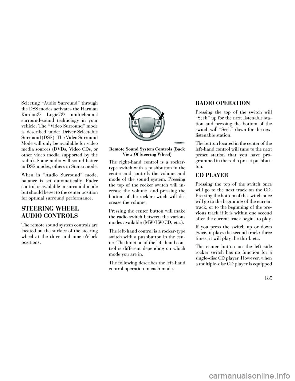
The remote sound system controls are
located on the surface of the steering
wheel at the three and nine o'clock
positions.The right-hand control is a rocker-
type switch with a pushbutton in the
center and controls the volume and
mode of the sound system. Pressing
the top of the rocker switch will in-
crease the volume, and pressing the
bottom of the rocker switch will de-
crease the volume.
Pressing the center button will make
the radio switch between the various
modes available (MW/LW/CD, etc.).
The left-hand control is a rocker-type
switch with a pushbutton in the cen-
ter. The function of the left-hand con-
trol is different depending on which
mode you are in.
The following describes the left-hand
control operation in each mode.
RADIO OPERATION
Pressing the top of the switch will
“Seek” up for the next listenable sta-
tion and pressing the bottom of the
switch will “Seek” down for the next
listenable station.
The button located in the center of the
left-hand control will tune to the next
preset station that you have pro-
grammed in the radio preset pushbut-
ton.
CD PLAYER
Pressing the top of the switch once
will go to the next track on the CD.
Pressing the bottom of the switch once
will go to the beginning of the current
track, or to the beginning of the pre-
vious track if it is within one second
after the current track begins to play.
If you press the switch up or down
twice, it plays the second track; three
times, it will play the third, etc.
The center button on the left side
rocker switch has no function for a
single-disc CD player. However, when
a multiple-disc CD player is equipped
Remote Sound System Controls (Back
View Of Steering Wheel)
185
Page 192 of 332

on the vehicle, the center button will
select the next available CD in the
player.
CD/DVD DISC
MAINTENANCE
To keep a CD/DVD in good condition,
take the following precautions:
1. Handle the disc by its edge; avoid
touching the surface.
2. If the disc is stained, clean the
surface with a soft cloth, wiping from
center to edge.
3. Do not apply paper or tape to the
disc; avoid scratching the disc.
4. Do not use solvents such as ben-
zene, thinner, cleaners, or anti-static
sprays.
5. Store the disc in its case after play-
ing.
6. Do not expose the disc to direct
sunlight.
7. Do not store the disc where tem-
peratures may become too high.NOTE: If you experience diffi-
culty in playing a particular disc, it
may be damaged (i.e., scratched,
reflective coating removed, a hair,
moisture or dew on the disc) over-
sized, or have protection encoding.
Try a known good disc before con-
sidering disc player service.
RADIO OPERATION AND
MOBILE PHONES
Under certain conditions, the mobile
phone being on in your vehicle can
cause erratic or noisy performance
from your radio. This condition may
be lessened or eliminated by relocat-
ing the mobile phone antenna. This
condition is not harmful to the radio.
If your radio performance does not
satisfactorily “clear” by the reposi-
tioning of the antenna, it is recom-
mended that the radio volume be
turned down or off during mobile
phone operation.
CLIMATE CONTROLS
The air conditioning and heating sys-
tem is designed to make you comfort-
able in all types of weather. This sys-
tem can be operated through either
the controls on the instrument panel
or through the Uconnect® system dis-
play.
When the Uconnect® system is in dif-
ferent modes (Radio, Player, Settings,
More, etc.) the driver and passenger
temperature settings will be indicated
at the top of the display.
GENERAL OVERVIEW
Hard-Keys
The hard-keys are located below the
Uconnect® screen, in the center of the
instrument panel.
186
Page 224 of 332

The Electronic Brake Force Distribu-
tion (EBD) prevents the rear wheels
from over-braking and provides
greater control of available braking
forces applied to the rear axle.
When the vehicle is driven over
11 km/h, you may also hear a slight
clicking sound as well as some related
motor noises. These noises are the sys-
tem performing its self check cycle to
ensure that the ABS is working prop-
erly. This self check occurs each time
the vehicle is started and accelerated
past 11 km/h.
ABS is activated during braking un-
der certain road or stopping condi-
tions. ABS-inducing conditions can
include ice, snow, gravel, bumps, rail-
road tracks, loose debris, or panic
stops.
You also may experience the following
when the brake system goes into Anti-
Lock:
The ABS motor running (it maycontinue to run for a short time
after the stop), The clicking sound of solenoid
valves,
Brake pedal pulsations, and
A slight drop or fall away of the brake pedal at the end of the stop.
These are all normal characteristics of
ABS.
WARNING!
The ABS contains sophisticated electronic equipment that may be
susceptible to interference caused
by improperly installed or high
output radio transmitting equip-
ment. This interference can cause
possible loss of anti-lock braking
capability. Installation of such
equipment should be performed
by qualified professionals.
Pumping of the Anti-Lock Brakes will diminish their effectiveness
and may lead to a collision.
Pumping makes the stopping dis-
tance longer. Just press firmly on
your brake pedal when you need
to slow down or stop.
(Continued)
WARNING!(Continued)
The ABS cannot prevent thenatural laws of physics from act-
ing on the vehicle, nor can it in-
crease braking or steering effi-
ciency beyond that afforded by
the condition of the vehicle
brakes and tires or the traction
afforded.
The ABS cannot prevent colli- sions, including those resulting
from excessive speed in turns, fol-
lowing another vehicle too
closely, or hydroplaning.
The capabilities of an ABS equipped vehicle must never be
exploited in a reckless or danger-
ous manner that could jeopardize
the user's safety or the safety of
others.
All vehicle wheels and tires must be
the same size and type and tires must
be properly inflated to produce accu-
rate signals for the computer.
218
Page 241 of 332

will automatically update, the “In-
flate Tire to XX” message will no lon-
ger be displayed, the graphic display
in the EVIC will stop flashing or re-
turn to it's original color, and the TPM
Telltale Light will turn off. The ve-
hicle may need to be driven for up to
20 minutes above 24 km/h in order
for the TPMS to receive this informa-
tion.
Service TPMS Warning
If a system fault is detected, the TPM
Telltale Light will flash on and off for
75 seconds and then remain on solid.
The system fault will also sound a
chime. In addition, the EVIC will dis-
play a "SERVICE TPM SYSTEM"
message for a minimum of five sec-
onds and then display dashes (- -) in
place of the pressure value to indicate
which sensor is not being received.
If the ignition switch is cycled, this
sequence will repeat, providing the
system fault still exists. If the system
fault no longer exists, the TPM Tell-
tale Light will no longer flash, and the
"SERVICE TPM SYSTEM" message
will no longer display, and a pressurevalue will display in place of the
dashes. A system fault can occur due
to any of the following:
1. Signal interference due to elec-
tronic devices or driving next to facili-
ties emitting the same radio frequen-
cies as the TPM sensors.
2. Installing aftermarket window
tinting that contains materials that
may block radio wave signals.
3. Accumulation of snow or ice
around the wheels or wheel housings.
4. Using tire chains on the vehicle.
5. Using wheels/tires not equipped
with TPM sensors.
The EVIC will also display a "SER-
VICE TPM SYSTEM" message for a
minimum of five seconds when a sys-
tem fault related to an incorrect sen-
sor location fault is detected. In this
case, the "SERVICE TPM SYSTEM"
message is then followed with a
graphic display with pressure values
still shown. This indicates that the
pressure values are still being received
from the TPM sensors but they may
not be located in the correct vehicle
position. The system still needs to be
serviced as long as the "SERVICE
TPM SYSTEM" message is displayed.
Vehicles With Compact Spare
1. The compact spare tire does not
have a TPM sensor. Therefore, the
TPMS will not monitor the pressure in
the compact spare tire.
2. If you install the compact spare
tire in place of a road tire that has a
pressure below the low-pressure
warning limit, upon the next ignition
switch cycle, the TPM Telltale Light
will remain ON and a chime will
sound. In addition, the graphic in the
EVIC will still display a flashing or
different color pressure value.
3. After driving the vehicle for up to
20 minutes above 24 km/h, the TPM
Telltale Light will flash on and off for
75 seconds and then remain on solid.
In addition, the EVIC will display a
"SERVICE TPM SYSTEM" message
for a minimum of five seconds and
then display dashes (- -) in place of
the pressure value.
235
Page 266 of 332

posts are located on the right side of
the engine compartment for jump-
starting.
NOTE: The remote battery posts
are viewed by standing on the right
side of the vehicle looking over the
fender.
WARNING!
Take care to avoid the radiatorcooling fan whenever the hood is
raised. It can start anytime the
ignition switch is ON. You can be
injured by moving fan blades.
(Continued)
WARNING!(Continued)
Remove any metal jewelry suchas rings, watch bands and brace-
lets that could make an inadver-
tent electrical contact. You could
be seriously injured.
Batteries contain sulfuric acid that can burn your skin or eyes
and generate hydrogen gas which
is flammable and explosive. Keep
open flames or sparks away from
the battery.
1. Set the parking brake, shift the
automatic transmission into PARK
and turn the ignition to LOCK.
2. Turn off the heater, radio, and all
unnecessary electrical accessories.
3. If using another vehicle to jump-
start the battery, park the vehicle
within the jumper cables reach, set
the parking brake and make sure the
ignition is OFF.
WARNING!
Do not allow vehicles to touch each
other as this could establish a
ground connection and personal in-
jury could result.
JUMP-STARTING
PROCEDURE
WARNING!
Failure to follow this procedure
could result in personal injury or
property damage due to battery ex-
plosion.
CAUTION!
Failure to follow these procedures
could result in damage to the
charging system of the booster ve-
hicle or the discharged vehicle.
1. Connect the positive (+)end of the
jumper cable to the remote positive
(+) post of the discharged vehicle.
Remote Battery Post Locations
1 — Remote Positive (+)Post
2 — Remote Negative (-)Post
260
Page 300 of 332

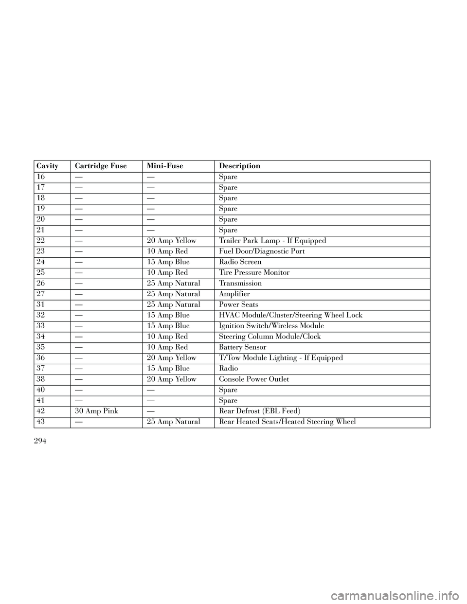
Cavity Cartridge Fuse Mini-Fuse Description
16 — — Spare
17 — — Spare
18 — — Spare
19 — — Spare
20 — — Spare
21 — — Spare
22 — 20 Amp Yellow Trailer Park Lamp - If Equipped
23 — 10 Amp Red Fuel Door/Diagnostic Port
24 — 15 Amp Blue Radio Screen
25 — 10 Amp Red Tire Pressure Monitor
26 — 25 Amp Natural Transmission
27 — 25 Amp Natural Amplifier
31 — 25 Amp Natural Power Seats
32 — 15 Amp Blue HVAC Module/Cluster/Steering Wheel Lock
33 — 15 Amp Blue Ignition Switch/Wireless Module
34 — 10 Amp Red Steering Column Module/Clock
35 — 10 Amp Red Battery Sensor
36 — 20 Amp Yellow T/Tow Module Lighting - If Equipped
37 — 15 Amp Blue Radio
38 — 20 Amp Yellow Console Power Outlet
40 — — Spare
41 — — Spare
42 30 Amp Pink — Rear Defrost (EBL Feed)
43 — 25 Amp Natural Rear Heated Seats/Heated Steering Wheel
294
Page 324 of 332

Airbag........42, 45, 60, 162
Alarm.................164
Anti-Lock..............164
Automatic Headlights......112
Brake Assist Warning.......223
Brake Warning...........163
Bulb Replacement.....296, 297
Dimmer Switch,
Headlight
...........115, 116
Electronic Stability Program (ESP)
Indicator
...............223
Exterior.................61
Fog...................160
Hazard Warning Flasher.....252
Headlights..........112, 297
Headlights On Reminder. . . .114
Headlights On With Wipers. . .113
Headlight Switch..........112
High Beam..............116
High Beam Indicator.......160
High Beam/Low Beam Select. .116
Illuminated Entry..........18
Instrument Cluster........112
Intensity Control..........117
Interior................116
License................298
Lights On Reminder.......114
Low Fuel...............168
Malfunction Indicator
(Check Engine)
...........162
Map Reading............116
Parade Mode
(Daytime Brightness)
.......117
Passing................116
Reading................116
Seat Belt Reminder........165
Security Alarm (Theft Alarm). .164
Service.............296, 297
Service Engine Soon
(Malfunction Indicator)
.....162
SmartBeams.............113
Theft Alarm (Security Alarm). .164
Tire Pressure Monitoring
(TPMS)
............161, 232
Traction Control..........223
Turn Signal..........61, 115
Vanity Mirror.............72
Wait to Start.............168
Warning (Instrument Cluster
Description)
.............160
Load Leveling System.........154
Locks.....................20
Automatic Door...........22
Auto Unlock..............22
Child Protection...........22
Door...................20
Power Door..............21
Low Tire Pressure System......232
Lubrication, Body...........276
Lug Nuts.................253
Maintenance Free Battery......274
Maintenance, General.........271
Maintenance Procedures.......271
Maintenance Schedule.....306, 309
Malfunction Indicator Light(Check Engine)
...........162
Master Cylinder (Brakes).......283
Memory Feature (Memory Seat). .109
Memory Seat...............109
Memory Seats and Radio.......109
Methanol.................237
Methanol Fuel..............237
Mini-Trip Computer..........173
Mirrors....................70
Automatic Dimming........70
Electric Powered...........71
Electric Remote...........71
Exterior Folding...........70
Heated.................72
Outside.................70
Vanity..................72
ModeFuel Saver
..............172
Modifications/Alterations, Vehicle...7
Monitor, Tire Pressure System. . .232
318
Page 325 of 332

Multi-Function Control Lever. . . .115
Navigation System(Uconnect® gps)
.......142, 183
New Vehicle Break-In Period.....58
Occupant Restraints.....28, 41, 44
Occupant Restraints(Sedan)
............40, 41, 43
Octane Rating, Gasoline(Fuel)
..............236, 300
Odometer.................160
Oil Change Indicator......160, 171
Oil Change Indicator, Reset. .160, 171
Oil, Engine............272, 300
Capacity...............299
Change Interval.......171, 272
Diesel.................273
Dipstick................272
Filter..............273, 300
Materials Added to........273
Recommendation. .272, 273, 299
Synthetic...............273
Viscosity...............299
Oil Filter, Selection...........273
Onboard Diagnostic System.....271
Operating Precautions.........271
Operator Manual (Owner's Manual)...6
Outside Rearview Mirrors.......70
Overdrive.................211
Overdrive OFF Switch.........211
Overhead Console............143
Overheating, Engine......165, 252
Owner's Manual (Operator Manual)...6
Paint Care.................286
Parking Brake..............216
ParkSense System, Rear.......137
Passing Light...............116
Pedals, Adjustable...........122
Pets......................58
PowerDeck Lid Release
..........27
Distribution Center
(Fuses)
............290, 292
Door Locks..............21
Mirrors.................71
Outlet (Auxiliary Electrical
Outlet)
................147
Seats..................103
Steering................215
Sunroof................144
Tilt/Telescoping Steering
Column
................120
Windows................25
Power Steering Fluid..........301
Pregnant Women and Seat Belts. . .38
PretensionersSeat Belts
................35
Programming Transmitters(Remote Keyless Entry)
.......18
Radial Ply Tires.............226
Radiator Cap (Coolant PressureCap)
...................281
Radio Operation.............186
Radio Remote Controls........185
Radio (Sound Systems)........183
Rain Sensitive Wiper System. . . .119
Rear Axle (Differential)........286
Rear Camera...............142
Rear Cupholder.............150
Rear Fog Lights.............115
Rear ParkSense System........137
Rear Seat, Folding...........108
Rear Window Defroster........153
Rear Window Features........153
Recorder, Event Data..........46
Recreational Towing..........250
Refrigerant................275
Reminder, Lights On..........114
Reminder, Seat Belt...........37
Remote Keyless Entry (RKE).....18
Remote Sound System (Radio)Controls
................185
Remote Trunk Release..........27
319
Page 326 of 332

Replacement Bulbs...........296
Replacement Keys............14
Replacement Parts...........271
Replacement Tires...........230
Resetting Oil ChangeIndicator
............160, 171
Restraint, Head.............107
Restraints, Child.............47
Restraints, Occupant...........28
Rocking Vehicle When Stuck. . . .261
Rotation, Tires..............232
Safety Checks Inside Vehicle.....60
Safety Checks Outside Vehicle....61
Safety, Exhaust Gas...........59
Safety Tips.................59
Schedule, Maintenance. . . .306, 309
Seat Belt Maintenance.........289
Seat Belt Reminder............37
Seat Belts.............28, 31, 60
Adjustable Upper Shoulder
Anchorage
...............33
And Pregnant Women.......38
Child Restraint............47
Front Seat...............31
Inspection...............60
Operating Instructions.......31
Pretensioners.............35
Rear Seat................31
Untwisting Procedure.......33
Seats....................103
Adjustment.............103
Easy Entry..............111
Head Restraints..........107
Height Adjustment........103
Memory................109
Power.................103
Rear Folding............108
Seatback Release..........108
Tilting.................103
Selection of Coolant(Antifreeze)
..........280, 300
Selection of Oil.............273
Sentry Key (Immobilizer).......14
Sentry Key Programming.......14
Sentry Key Replacement........14
Service Engine Soon Light(Malfunction Indicator)
......162
Setting the Clock............184
Shifting..................201
Automatic Transmission.....201
Shift Lever Override..........263
Shoulder Belts...............31
Shoulder Belt Upper Anchorage. . .33
Side Airbag.................43
Side View Mirror Adjustment.....70
Signals, Turn........61, 115, 160
SmartBeams...............113
Snow Chains (Tire Chains).....231
Snow Tires................227
Sound SystemKicker
.................184
Sound Systems..............183
Sound Systems (Radio)........183
Spare Tire.............228, 229
Spark Plugs................300
SpecificationsFuel (Gasoline)
.......236, 300
Oil...............273, 300
Speed Control(Cruise Control)
.......123, 125
Speedometer...............162
Starting..................197
Cold Weather............198
Engine Fails to Start.......198
Starting and Operating........197
Starting Procedures..........197
SteeringColumn Controls
..........115
Column Lock............120
Power.................215
Tilt Column.............120
Wheel, Heated...........121
Wheel, Tilt..............120
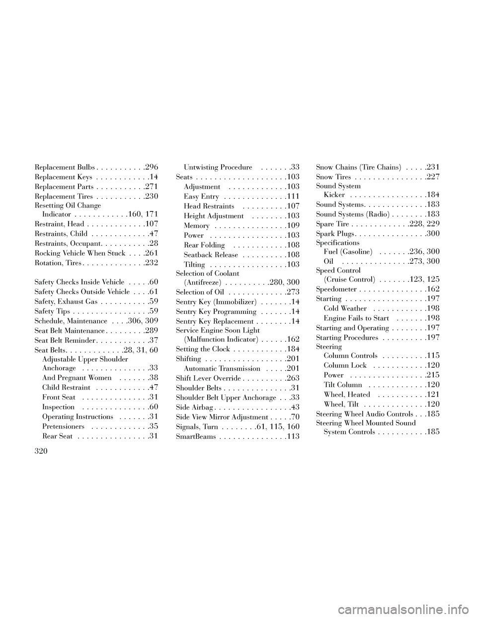
Steering Wheel Audio Controls. . .185
Steering Wheel Mounted SoundSystem Controls
...........185
320