steering Lancia Thesis 2006 Owner handbook (in English)
[x] Cancel search | Manufacturer: LANCIA, Model Year: 2006, Model line: Thesis, Model: Lancia Thesis 2006Pages: 386, PDF Size: 8.69 MB
Page 11 of 386
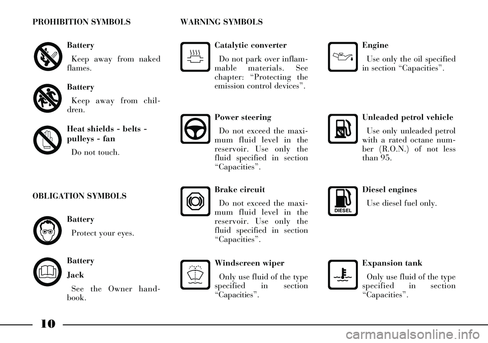
Diesel engines
Use diesel fuel only.
DIESEL
Expansion tank
Only use fluid of the type
specified in section
“Capacities”.
Battery
Protect your eyes.
Battery
Jack
See the Owner hand-
book.
OBLIGATION SYMBOLS
10
Battery
Keep away from naked
flames.
Battery
Keep away from chil-
dren.
Heat shields - belts -
pulleys - fan
Do not touch.
PROHIBITION SYMBOLS
Power steering
Do not exceed the maxi-
mum fluid level in the
reservoir. Use only the
fluid specified in section
“Capacities”.
Catalytic converter
Do not park over inflam-
mable materials. See
chapter: “Protecting the
emission control devices”.
WARNING SYMBOLS
Engine
Use only the oil specified
in section “Capacities”.
Unleaded petrol vehicle
Use only unleaded petrol
with a rated octane num-
ber (R.O.N.) of not less
than 95.
Windscreen wiper
Only use fluid of the type
specified in section
“Capacities”.
Brake circuit
Do not exceed the maxi-
mum fluid level in the
reservoir. Use only the
fluid specified in section
“Capacities”.
Page 14 of 386
13
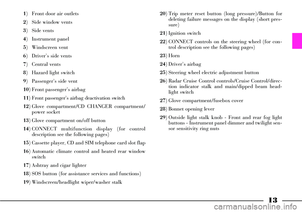
1) Front door air outlets
2) Side window vents
3) Side vents
4) Instrument panel
5) Windscreen vent
6) Driver’s side vents
7) Central vents
8) Hazard light switch
9) Passenger’s side vent
10) Front passenger’s airbag
11) Front passenger’s airbag deactivation switch
12) Glove compartment/CD CHANGER compartment/
power socket
13) Glove compartment on/off button
14) CONNECT multifunction display (for control
description see the following pages)
15) Cassette player, CD and SIM telephone card slot flap
16) Automatic climate control and heated rear window
switch
17) Ashtray and cigar lighter
18) SOS button (for assistance services and functions)
19) Windscreen/headlight wiper/washer stalk 20) Trip meter reset button (long pressure)/Button for
deleting failure messages on the display (short pres-
sure)
21) Ignition switch
22) CONNECT controls on the steering wheel (for con-
trol description see the following pages)
23) Horn
24) Driver’s airbag
25) Steering wheel electric adjustment button
26) Radar Cruise Control controls/Cruise Control/direc-
tion indicator stalk and main/dipped beam head-
light switch
27) Glove compartment/fusebox cover
28) Bonnet opening lever
29) Outside light stalk knob - Front and rear fog light
buttons - Instrument panel dimmer and twilight sen-
sor sensitivity ring nuts
Page 19 of 386
18
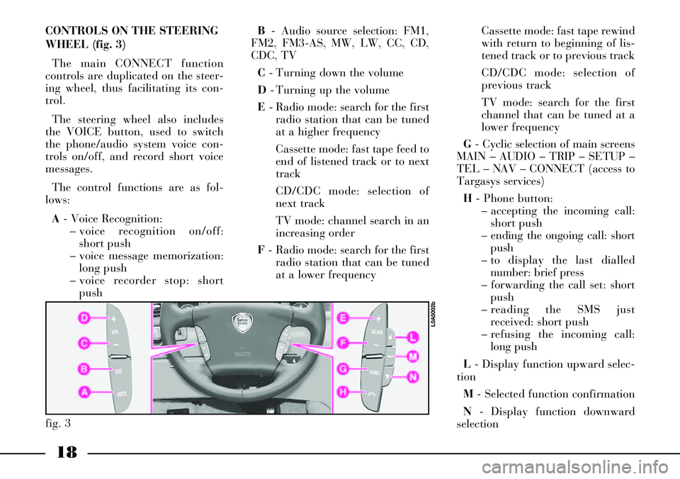
CONTROLS ON THE STEERING
WHEEL (fig. 3)
The main CONNECT function
controls are duplicated on the steer-
ing wheel, thus facilitating its con-
trol.
The steering wheel also includes
the VOICE button, used to switch
the phone/audio system voice con-
trols on/off, and record short voice
messages.
The control functions are as fol-
lows:
A- Voice Recognition:
– voice recognition on/off:
short push
– voice message memorization:
long push
– voice recorder stop: short
pushB- Audio source selection: FM1,
FM2, FM3-AS, MW, LW, CC, CD,
CDC, TV
C- Turning down the volume
D- Turning up the volume
E- Radio mode: search for the first
radio station that can be tuned
at a higher frequency
Cassette mode: fast tape feed to
end of listened track or to next
track
CD/CDC mode: selection of
next track
TV mode: channel search in an
increasing order
F- Radio mode: search for the first
radio station that can be tuned
at a lower frequencyCassette mode: fast tape rewind
with return to beginning of lis-
tened track or to previous track
CD/CDC mode: selection of
previous track
TV mode: search for the first
channel that can be tuned at a
lower frequency
G- Cyclic selection of main screens
MAIN – AUDIO – TRIP – SETUP –
TEL – NAV – CONNECT (access to
Targasys services)
H- Phone button:
– accepting the incoming call:
short push
– ending the ongoing call: short
push
– to display the last dialled
number: brief press
– forwarding the call set: short
push
– reading the SMS just
received: short push
– refusing the incoming call:
long push
L- Display function upward selec-
tion
M- Selected function confirmation
N- Display function downward
selection
fig. 3
L0A5002b
Page 22 of 386
21
Function
Audio module switching on
Audio module switching off
Audio mute (only with TP
active on the main
Radio screen)
Audio source selection
Turning the volumeup/down
Selection of stored
radio stations
Radio station memorization
Search for the first radio
station that can be tuned
at a higher frequency
Search for the first radio
station that can be tuned
at a lower frequencyCONNECT buttons
Short push on AUDIO button
Long push on AUDIO button
“Audio Mute” selection and con-
firmation on Radio menu by the
right knob 21(fig. 2)
Press the multifunction but-
tons FM, AM, CC, CD, CDC,
TV or the SOURCE button
Rotate the left-hand knob
Short push on buttons
1 to 6
Long push on buttons 1 to 6
Short push on button ˙
Short push on button ¯Steering wheel buttons
–
–
–
Press the SOURCEbutton
Press VOL+/- buttons
–
–
Short push on SCAN+ button
Short push on SCAN- buttonRemote control buttons
–
–
Press the ON/OFF key
Press the SOURCEbutton
Press VOL+ or VOL- buttons
Short push on buttons
1 to 6
Long push on buttons 1 to 6
Short push on button N
Short push on button O
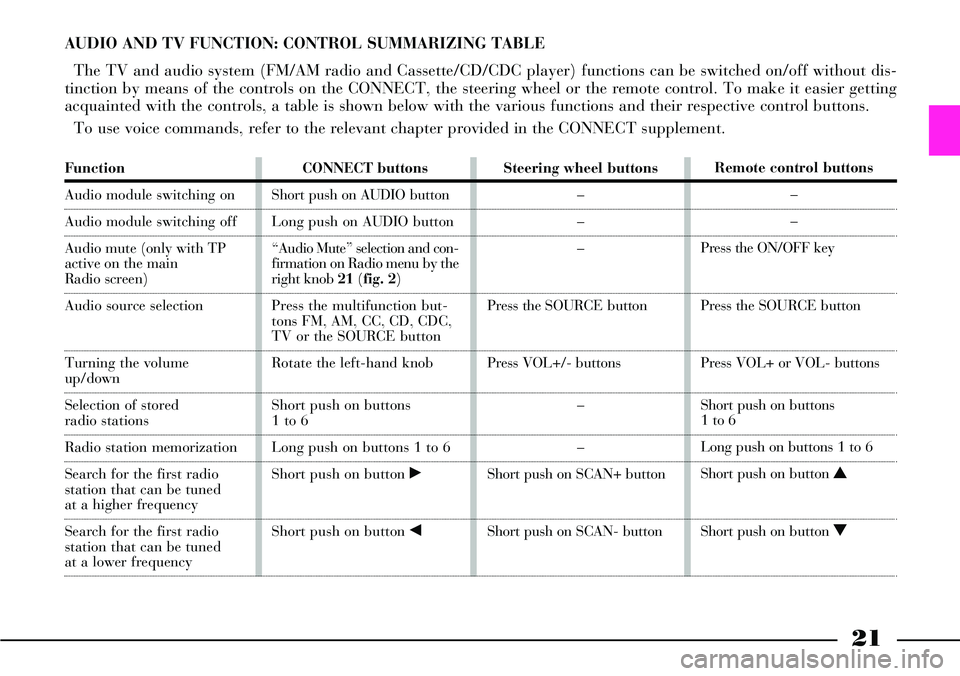
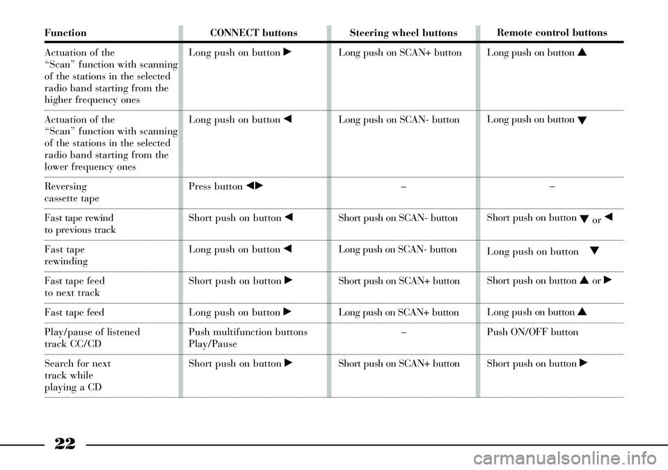
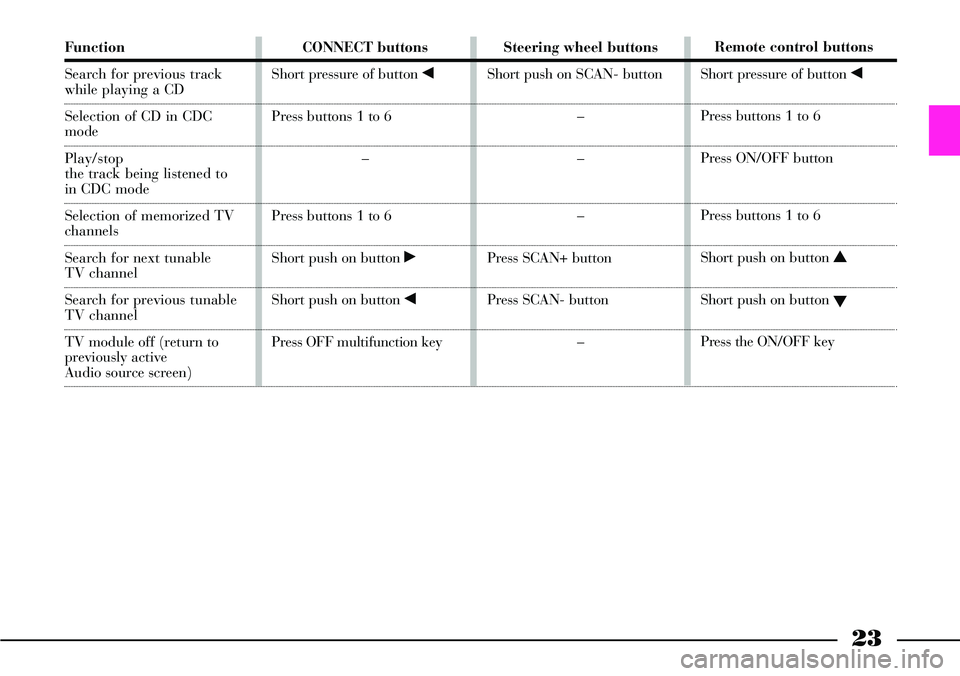
AUDIO AND TV FUNCTION: CONTROL SUMMARIZING TABLE
The TV and audio system (FM/AM radio and Cassette/CD/CDC player) functions can be switched on/off without dis-
tinction by means of the controls on the CONNECT, the steering wheel or the remote control. To make it easier getting
acquainted with the controls, a table is shown below with the various functions and their respective control buttons.
To use voice commands, refer to the relevant chapter provided in the CONNECT supplement.
Page 23 of 386
22
Function
Actuation of the
“Scan” function with scanning
of the stations in the selected
radio band starting from the
higher frequency ones
Actuation of the
“Scan” function with scanning
of the stations in the selected
radio band starting from the
lower frequency ones
Reversing
cassette tape
Fast tape rewind
to previous track
Fast tape
rewinding
Fasttape feed
to next track
Fast tape feed
Play/pause of listened
track CC/CD
Search for next
track while
playing a CD CONNECT buttons
Long push on button ˙
Long push on button ¯
Press button ¯˙
Short push on button ¯
Long push on button ¯
Short push on button ˙
Long push on button ˙
Push multifunction buttons
Play/Pause
Short push on button ˙Steering wheel buttons
Long push on SCAN+ button
Long push on SCAN- button
–
Short push on SCAN- button
Long push on SCAN- button
Short push on SCAN+ button
Long push on SCAN+ button
–
Short push on SCAN+ button Remote control buttons
Long push on button N
Long push on button
O
–
Short push on button
Oor ¯
Long push on buttonO
Short push on button Nor ˙
Long push on button N
Push ON/OFF button
Short push on button ˙
Page 24 of 386
23
Function
Search for previous track
while playing a CD
Selection of CD in CDC
mode
Play/stop
the track being listened to
in CDC mode
Selection of memorized TV
channels
Search for next tunable
TV channel
Search for previous tunable
TV channel
TV module off (return to
previously active
Audio source screen)CONNECT buttons
Short pressure of button ¯
Press buttons 1 to 6
–
Press buttons 1 to 6
Short push on button ˙
Short push on button ¯
Press OFF multifunction keySteering wheel buttons
Short push on SCAN- button
–
–
–
Press SCAN+ button
Press SCAN- button
–Remote control buttons
Short pressure of button ¯
Press buttons 1 to 6
Press ON/OFF button
Press buttons 1 to 6
Short push on button N
Short push on button
O
Press the ON/OFF key
Page 25 of 386
It is absolutely forbidden
to carry out whatever af-
ter-market operation in-
volving steering system or steering
column modifications (e.g.: instal-
lation of anti-theft Device) that
could badly affect performance
and safety, cause the lapse of war-
ranty and also result in non-com-
pliance of the car with homologa-
tion requirements.
24
STEERING COLUMN LOCK
The steering column lock is
engaged automatically after remov-
ing the ignition key.IGNITION
SWITCH
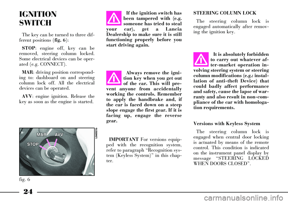
The key can be turned to three dif-
ferent positions (fig. 6):
STOP: engine off, key can be
removed, steering column locked.
Some electrical devices can be oper-
ated (e.g. CONNECT).
MAR: driving position correspond-
ing to: dashboard on and steering
column lock off. All the electrical
devices can be operated.
AVV: engine ignition. Release the
key as soon as the engine is started.If the ignition switch has
been tampered with (e.g.
someone has tried to steal
your car), get a Lancia
Dealership to make sure it is still
functioning properly before you
start driving again.
Always remove the igni-
tion key when you get out
of the car. This will pre-
vent anyone from accidentally
working the controls. Remember
to apply the handbrake and, if
the car is faced down on a steep
slope engage the first gear. If it is
facing up, engage the reverse
gear.
IMPORTANTFor versions equip-
ped with the recognition system,
refer to paragraph “Recognition sys-
tem (Keyless System)” in this chap-
ter.
fig. 6
L0A0021b
Versions with Keyless System
The steering column lock is
engaged when central door locking
is actuated by means of the remote
control. This condition is indicated
on the instrument panel display by
message “STEERING LOCKED
WHEN DOORS CLOSED”.
Page 26 of 386
25
Steering column lock always off
The user can set the condition
“Steering column lock always off”
by means of the CONNECT menu.
To set this mode, refer to the CON-
NECT supplement provided with
the car.
In an emergency
The steering column lock cannot be
disengaged when the battery is run
down. In this case, open the bonnet
with the emergency key and connect
an auxiliary battery to the car bat-
tery.Do not carry out this
procedure if you lack
experience; if it is not
done correctly it can cause very
intense electrical discharges and
the battery might even explode.
Contact a Lancia Dealership. In
any case, refer to paragraph
“Jump starting”. The steering column
lock is not engaged if cen-
tral door locking is actu-
ated by means of the emergency
key or if central locking is acti-
vated automatically (“Autoclose”
function).
The steering column lock is disen-
gaged automatically when depress-
ing the clutch pedal (versions with
manual gearbox) or brake pedal
(versions with automatic transmis-
sion).
Before opening the lug-
gage compartment bonnet
to reload the battery or to
connect an auxiliary battery, care-
fully read and comply with the in-
structions contained in the para-
graph “If battery is to be discon-
nected” in the chapter “In an
emergency”.
Page 29 of 386
28
The key operates:
– ignition switch;
– steering column lock disengage-
ment;
– front door lock latches;
– dead lock device;
– remote door opening/closing;
– remote bonnet lock locking/
unlocking;
– remote boot lock locking/unlock-
ing;
– remote bonnet opening;
– electronic alarm system;
– passenger side airbag deactiva-
tion;
– rear airbag deactivation;
– window and sunroof opening/
closing.The electronic compo-
nents inside the key may
be damaged if the key is
exposed to direct sunlight.Code card
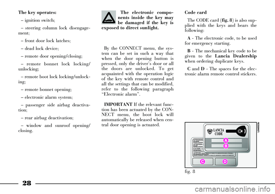
The CODE card (fig. 8) is also sup-
plied with the keys and bears the
following:
A- The electronic code, to be used
for emergency starting.
B- The mechanical key code to be
given to the Lancia Dealership
when ordering duplicate keys.
Cand D- The spaces for the elec-
tronic alarm remote control stickers. By the CONNECT menu, the sys-
tem can be set in such a way that
when the door opening button is
pressed, only the driver’s door or all
the doors are unlocked. To get
acquainted with the operation logic
of the key with remote control and
all the settings that can be modified,
refer to the following paragraph
“Electronic alarm”.
IMPORTANTIf the relevant func-
tion has been actuated by the CON-
NECT menu, the boot lock will
automatically be released when cen-
tral door opening is actuated.
fig. 8
L0A0023b
Page 31 of 386
30
After activating the dead
lock device it will be
impossible to get out of
the passenger compartment: for
this reason this device must be
activated only after making sure
that the passenger compartment
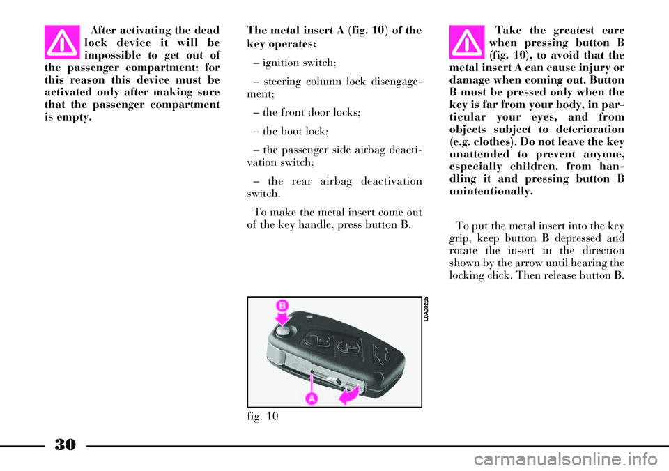
is empty.The metal insert A (fig. 10) of the
key operates:
– ignition switch;
– steering column lock disengage-
ment;
– the front door locks;
– the boot lock;
– the passenger side airbag deacti-
vation switch;
– the rear airbag deactivation
switch.
To make the metal insert come out
of the key handle, press button B.Take the greatest care
when pressing button B
(fig. 10), to avoid that the
metal insert A can cause injury or
damage when coming out. Button
B must be pressed only when the
key is far from your body, in par-
ticular your eyes, and from
objects subject to deterioration
(e.g. clothes). Do not leave the key
unattended to prevent anyone,
especially children, from han-
dling it and pressing button B
unintentionally.
To put the metal insert into the key
grip, keep button Bdepressed and
rotate the insert in the direction
shown by the arrow until hearing the
locking click. Then release button B.
fig. 10
L0A0025b