key battery Lancia Thesis 2007 Owner handbook (in English)
[x] Cancel search | Manufacturer: LANCIA, Model Year: 2007, Model line: Thesis, Model: Lancia Thesis 2007Pages: 386, PDF Size: 8.69 MB
Page 55 of 386
54
DOORS
fig. 29
L0A0174b
Before opening a door,
check whether this opera-
tion can be performed
under safety conditions.
OPENING/CLOSING FROM THE
OUTSIDE
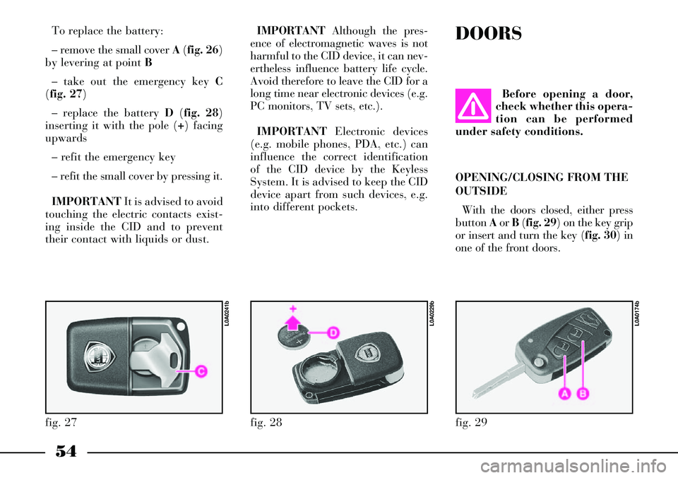
With the doors closed, either press
button Aor B(fig. 29) on the key grip
or insert and turn the key (fig. 30) in
one of the front doors.
IMPORTANTAlthough the pres-
ence of electromagnetic waves is not
harmful to the CID device, it can nev-
ertheless influence battery life cycle.
Avoid therefore to leave the CID for a
long time near electronic devices (e.g.
PC monitors, TV sets, etc.).
IMPORTANTElectronic devices
(e.g. mobile phones, PDA, etc.) can
influence the correct identification
of the CID device by the Keyless
System. It is advised to keep the CID
device apart from such devices, e.g.
into different pockets. To replace the battery:
– remove the small cover A(fig. 26)
by levering at point B
– take out the emergency key C
(fig. 27)
– replace the battery D(fig. 28)
inserting it with the pole (+) facing
upwards
– refit the emergency key
– refit the small cover by pressing it.
IMPORTANTIt is advised to avoid
touching the electric contacts exist-
ing inside the CID and to prevent
their contact with liquids or dust.
fig. 27
L0A0241b
fig. 28
L0A0229b
Page 56 of 386
55
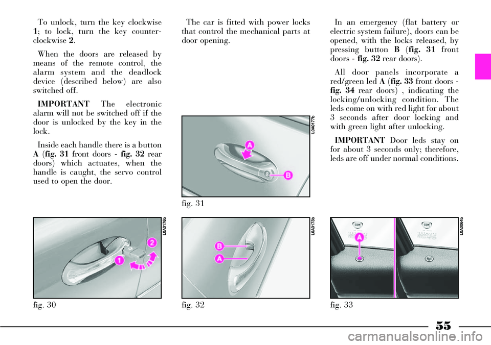
To unlock, turn the key clockwise
1; to lock, turn the key counter-
clockwise 2.
When the doors are released by
means of the remote control, the
alarm system and the deadlock
device (described below) are also
switched off.
IMPORTANTThe electronic
alarm will not be switched off if the
door is unlocked by the key in the
lock.
Inside each handle there is a button
A(fig. 31 front doors -fig. 32 rear
doors) which actuates, when the
handle is caught, the servo control
used to open the door.The car is fitted with power locks
that control the mechanical parts at
door opening.
fig. 30
L0A0176b
fig. 32
L0A0173b
fig. 31
L0A0177b
In an emergency (flat battery or
electric system failure), doors can be
opened, with the locks released, by
pressing button B(fig. 31 front
doors -fig. 32 rear doors).
All door panels incorporate a
red/green led A(fig. 33 front doors -
fig. 34 rear doors) , indicating the
locking/unlocking condition. The
leds come on with red light for about
3 seconds after door locking and
with green light after unlocking.
IMPORTANTDoor leds stay on
for about 3 seconds only; therefore,
leds are off under normal conditions.
fig. 33
L0A0064b
Page 60 of 386
59
AUTOCLOSE FUNCTION
(AUTOMATIC LOCKING
WITH KEYLESS SYSTEM
RECOGNITION SYSTEM)
On versions equipped with Keyless
System, the “Autoclose” function
can be actuated/deactivated through
the CONNECT settings. This func-
tion makes it possible to automati-
cally lock the boot and doors when
the CID device is taken away from
the car.
When leaving the car, if one or
more doors are not closed correctly,
the car will remain open and a fur-
ther beep will sound to indicate that
the locks have not been locked.
The “Autoclose” functions actuates
neither the alarm system nor the
door deadlock device (refer to the
contents of the relevant paragraph).
In any case, these functions can be
actuated by means of the remote
control.LOCK RELEASE IN CASE OF
ACCIDENT
In case of collision with actuation
of the inertia switch, the door locks
are automatically released to allows
rescuers to get access to the passen-
ger compartment.In any case, door open-
ing from the outside
depends on the door con-
ditions after the collision:
deformed doors cannot very often
be opened even if the lock is
released. In such a case, try to
open the other doors.
INITIALISING THE DOOR
LOCKING CONTROL UNIT
Whenever the battery is electrically
connected again or it is reloaded
after being completely flat or after
replacing one of the protection fuses,
to restore the correct operation of
the door locking, of air conditioning
and of ESP system, it is necessary to
perform the initialisation operations
contained in the paragraph “If bat-
tery is to be disconnected” in the
chapter “In an emergency”. The external mechanical
connections are active
only when the doors are
unlocked.
In the event that the driver has
actuated central locking from the
inside and, after a collision, the
inertia switch has not actuated
the automatic door unlocking
function due to the loss of or
damage to the battery, access to
the passenger compartment will
not be possible from the outside.
Page 111 of 386
110
KILOMETRE COUNTER (AND
TRIP METER) AND AUTOMATIC
GEARBOX
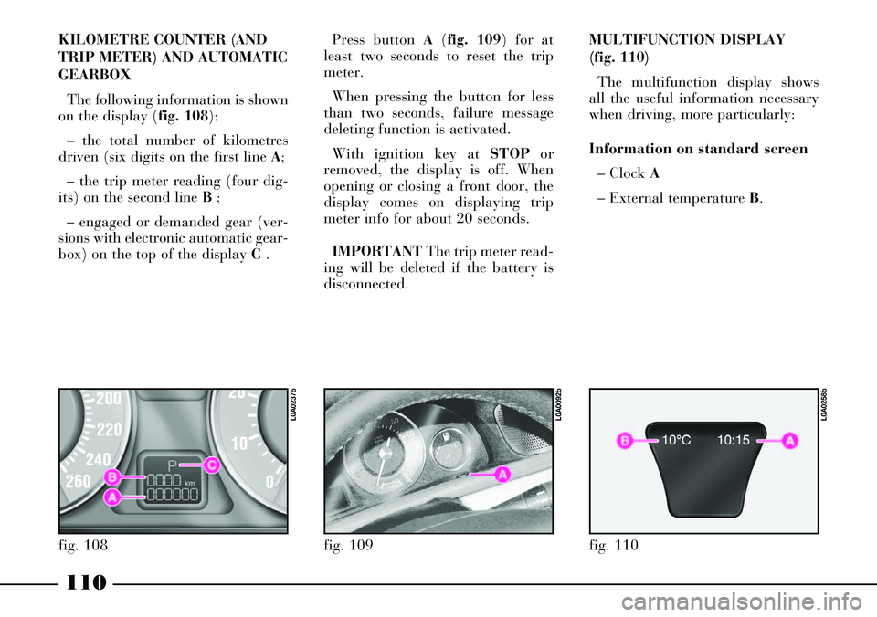
The following information is shown
on the display (fig. 108):
– the total number of kilometres
driven (six digits on the first line A;
– the trip meter reading (four dig-
its) on the second line B ;
– engaged or demanded gear (ver-
sions with electronic automatic gear-
box) on the top of the display C .Press button A(fig. 109) for at
least two seconds to reset the trip
meter.
When pressing the button for less
than two seconds, failure message
deleting function is activated.
With ignition key at STOPor
removed, the display is off. When
opening or closing a front door, the
display comes on displaying trip
meter info for about 20 seconds.
IMPORTANTThe trip meter read-
ing will be deleted if the battery is
disconnected.
fig. 108
L0A0237b
fig. 109
L0A0092b
MULTIFUNCTION DISPLAY
(fig. 110)
The multifunction display shows
all the useful information necessary
when driving, more particularly:
Information on standard screen
– Clock A
– External temperature B.
fig. 110
L0A0258b
Page 165 of 386
164
This function can be activated with
the CONNECT (from the main
SETUP screen) or with the remote
control.
The system works with this mode on
if the following conditions are present
– outside temperature lower than 20
°C
– coolant temperature lower than 50
°C
– ignition key at STOPor removed
– car battery charged
– fuel not in reserve.
When this mode is on, the heater is
deactivated when one of the following
conditions occur:
– end of planned working time
– OFF signal from the remote con-
trol
– manual shutdown by the user
through CONNECT– ignition key at MAR
– partial battery rundown
– fuel in reserve
– malfunction detected by the heater
control unit.
Timed heater activation/
deactivation through CONNECT
Timed heater activation and deacti-
vation can be set through the CON-
NECT. Select and confirm “Heater”
on the main SETUP screen to display
the parked-car heater settings.
Settings available are the following:
– Operate now
– Timer 1
– Timer 2.
To activate/deactivate the required
function, select and confirm it with
the CONNECT right knob.“Operate now”
The option “Operate now” enables
to warm the passenger compartment
with the engine stopped and warm
and the ignition key to MAR, using
the engine coolant, heater coolant cir-
culation pump, automatic air distrib-
ution control (if not set manually) and
closing air recirculation. The timer
cannot be programmed when this
function is on.
To guarantee the required comfort,
this function shall be mainly activated
when coolant is hot enough. When
coolant temperature is lower than 50
°C the control unit starts the heater,
and when temperature is over 70 °C,
the control unit turns the heater off
and lets only the coolant circulation
pump keep on working.
Page 166 of 386
165
The “parked-car heater” mode is
automatically deactivated when one
of the following conditions takes
place:
– engine started
– limit time (around 30 minutes) of
heater and/or coolant pump func-
tioning overcome
– turn off requested by the user
through the CONNECT
– malfunction detected by the heater
control unit
– partial battery run-down or alter-
nator fault.
“Timer 1” and “Timer 2”
The “Timer” options shall be used
to programme two heater daily cycles;
for each cycle enter the time of acti-
vation and the length of operation
both with 5 minute intervals.
Each cycle cannot last more than 60
minutes. The default operation is 15
minutes. The timer works regardless
of the ignition key position.During heater operation, messages
referred to the following conditions
are shown on CONNECT display:
– fuel level in reserve (continue any-
way?)
– fuel level in reserve. Parked-car
heater has been switched off
– parked-car heater not operating
because of cooling down
– parked-car heater not operating
because external temperature is
higher than 20 °C
– parked-car heater not operating
because motor is on
– parked-car heater has been
switched off because of low voltage.IMPORTANTFor safety reasons,
the timer must be programmed/con-
firmed at any activation and con-
firmed not later than 24 hours since
programming. In addition, the user
must confirm every time the timer ac-
tivation. The timer does not automat-
ically correct standard time.
The timer can be in one of the fol-
lowing conditions:
– off: in this condition the timer is
programmable and parameters can be
loaded or adjusted. Loaded parame-
ters should be valued and approved
by CONNECT
– on: activated parameters approved
by CONNECT are stored in the mem-
ory. The user confirms the set cycle
waiting for the programmed activa-
tion moment which is indicated on the
CONNECT display
– active: the heater is working in
“programmable heater” mode con-
trolled by the timer present on the
CONNECT display. When the timer
is activated, the CONNECT records
the system conditions
Page 168 of 386

167
This control is accepted by CON-
NECT only if:
– outside temperature lower than 20
°C
– coolant temperature lower than 50
°C
– the ignition key is at STOPor re-
moved
– car battery charged
– sufficient fuel level
– the timer is deactivated.
Switching the heater on
To switch the heater on, press the
remote control button ONfor 1 or 2
seconds, while keeping the antenna in
vertical position; the positive or un-
successful activation is indicated by
the remote control red led Bin the fol-
lowing way:
– the led turns on for about 2 sec-
onds = the signal has been correctly
received and the heater has been ac-
tivated– the led flashes for about 2 seconds
= the signal has not been received.
In the latter case you are advised to
move before trying to activate it by
pressing again the ONbutton.
After the confirmation activation,
the led Bwill flash every 2 seconds for
the whole operation cycle duration.
IMPORTANTIf led Bturns on with
green colour, press twice both remote
control buttons ONand OFFwithin 1
second to set the red colour.
Activation length
When pressing the remote control
button ONthe last recorded activa-
tion length is always activated.
To see the recorded length, press at
the same time for three consecutive
times within 1 second, the remote
control buttons ONand OFF, count
the number of flashes of led Bthen
compare them to those shown in the
table below, including also the first
flash appearing the third time you
press the buttons. Default activation length is 30 min-
utes but it can be changed through
the following procedure:
– press at the same time for three
consecutive times within 1 second, the
remote control buttons ONand OFF
– count the number of flashes of led
Bincluding also the first flash ap-
pearing the third time you press but-
tons ONand OFF
– press OFFto set the length suc-
cessive to the set one (press OFFfor
several times to set the required
length in sequence)
– wait for about 10 seconds for timer
storing.
Page 173 of 386
172
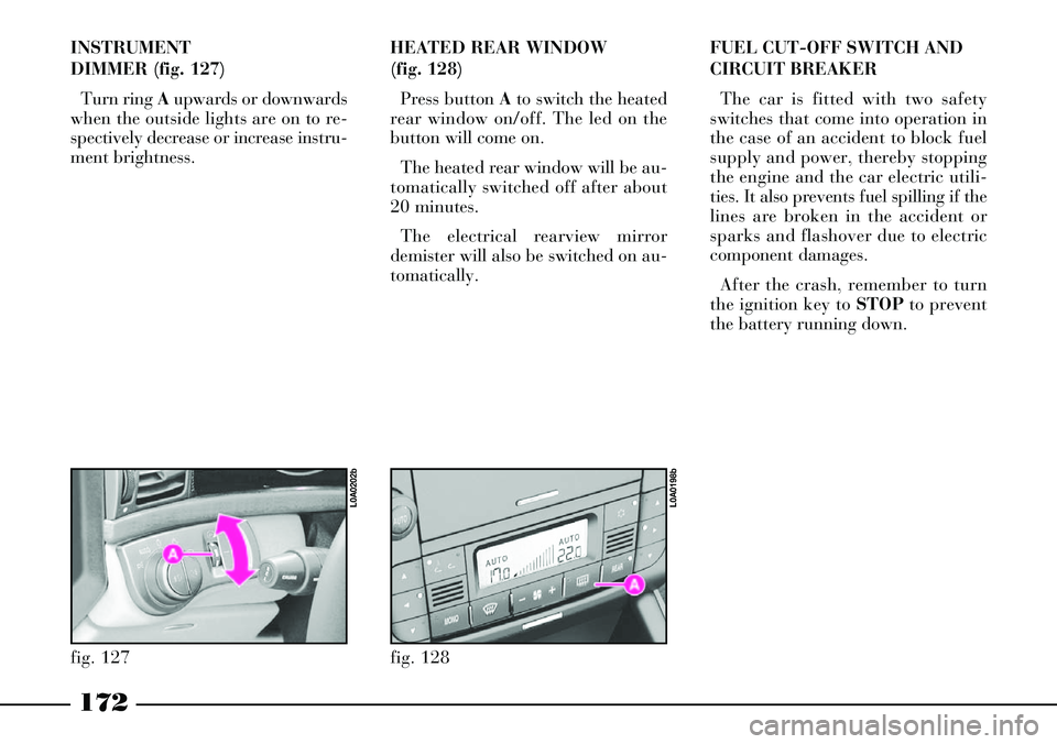
INSTRUMENT
DIMMER (fig. 127)
Turn ring Aupwards or downwards
when the outside lights are on to re-
spectively decrease or increase instru-
ment brightness.HEATED REAR WINDOW
(fig. 128)
Press button Ato switch the heated
rear window on/off. The led on the
button will come on.
The heated rear window will be au-
tomatically switched off after about
20 minutes.
The electrical rearview mirror
demister will also be switched on au-
tomatically.
fig. 127
L0A0202b
fig. 128
L0A0198b
FUEL CUT-OFF SWITCH AND
CIRCUIT BREAKER
The car is fitted with two safety
switches that come into operation in
the case of an accident to block fuel
supply and power, thereby stopping
the engine and the car electric utili-
ties. It also prevents fuel spilling if the
lines are broken in the accident or
sparks and flashover due to electric
component damages.
After the crash, remember to turn
the ignition key to STOPto prevent
the battery running down.
Page 175 of 386

174
Lift cover Aset at the driver's left
and press button Bto reset the fuel
cut-off switch.
Resetting the circuit breaker
Before resetting the cir-
cuit breaker, carefully
check for any fuel leaks or
damages to the car electric devices
(e.g.: headlights).Circuit breaker is located on the left
side of the boot, inside a box directly
set and connected to the battery pos-
itive terminal.
To reach the circuit breaker:
1) Open the tailgate.
2) Loosen knob A(fig. 130) and re-
move the battery cover B.
3) Press tabs A(fig. 131) and re-
move cover B.
4) Press button A(fig. 132) to reset
the circuit breaker.Initialising the control units of
the door locks, air conditioner
and ESP system
After resetting the circuit breaker, to
restore correct door locking, air con-
ditioning and ESP system, perform
the following operations:
1) Close the doors and the tailgate,
fit the key into the lock of one of the
front doors and perform a door cen-
tralised opening/closing cycle.
2) Start the engine and turn on the
compressor of the conditioner, setting
a lower temperature value than that
of the environment and check
whether the led on the disconnection
push button of the conditioner com-
pressor òis lit.
3) Turn the steering wheel one
fourth turn at least (the car can be at
standstill but the engine shall be run-
ning) and start running the car for a
few metres in a straight line until the
ESP warning light
áis off.
fig. 131
L0A0031b
fig. 132
L0A0347b
Page 179 of 386

178
fig. 135
L0A0275b
fig. 134
L0A0274b
Fault indication
The system is controlled by an elec-
tronic control unit signalling possible
failures by turning on the s! warn-
ing light on the multifunction display
together with the message “EPB
FAULT - GO TO DEALER”.
For a higher safety, every time the
parking brake button is pressed dur-
ing a failure, a buzzer will sound to
draw the driver’s attention and the
xwarning light will turn on.
If the parking brake does not reach
the required working force (e.g.
when the battery is partially flat),
the instrument panel warning light
xstarts flashing.
In case of instrument panel warn-
ing light xfault, the s!warning
light on the multifunction display
turns on together with the message
“EPB INDICATOR FAULT - GO TO
DEALER” to informthe driver
about the dangerous situation. In case of failure indi-
cated by the related
warning light and mes-
sage turning on, drive carefully to
a Lancia Dealership because the
parking brake might not work.
Emergency disengagement
The electric parking brake is fitted
with an independent battery which
can be used to disengage the brake,
for instance when the car main bat-
tery is completely flat or it has bro-
ken after an accident.The additional battery, always
kept charged by a dedicated elec-
tronic control unit, can engage and
disengage the parking brake when it
is necessary to push manually the
car.
To engage and disengage the elec-
tric parking brake when the car
main battery is completely flat, turn
the key to MARand press the main
button on the central console.