Lancia Thesis 2007 Owner handbook (in English)
Manufacturer: LANCIA, Model Year: 2007, Model line: Thesis, Model: Lancia Thesis 2007Pages: 386, PDF Size: 8.69 MB
Page 271 of 386

270
– Reconnect the negative battery
terminal (-) after checking the bat-
tery charge.
IMPORTANT Before connecting
the battery again carefully read and
comply with instructions contained
in the paragraph “If battery is to be
disconnected” in the chapter “In an
emergency”.
– With the gear lever to neutral,
start the engine and let it idle a few
minutes, pressing the clutch pedal
repeatedly.
This operation must be
carried out outdoor.
Exhaust gas contains car-
bon monoxide, an extremely
toxic gas.USEFUL
ACCESSORIES
In addition to the legal require-
ments we recommend keeping the
following in the car (fig. 2):
– first-aid kit with non-alcoholic
base disinfectant, sterile gauze, a roll
of gauze bandage, plasters, etc.,
– torch,
– round-nosed scissors,
– work gloves,
- fire extinguisher.
These articles are all available from
Lineaccessori Lancia range.
fig. 2
L0A0170b
Page 272 of 386

271
EMERGENCY
START-UP
If the Lancia CODE system cannot
deactivate the engine immobilising
system, symbols Yand Uwill
remain lit on the multifunction dis-
play together with messages
“ELECTRONIC KEY NOT
RECOGNISED” and “ENGINE
CONTROL SYSTEM FAULT”, and
the engine will not start. Follow the
emergency start-up procedure to
start the engine.
Read the whole procedure care-
fully before trying to carry it out.
If you make a mistake in the emer-
gency procedure you must turn the
ignition key back to STOP and
repeat the whole operation from the
beginning (step 1).
1) Read the five-digit electronic
code on the CODE card.
2) Turn the ignition key to MAR.3) Press and hold down the accel-
erator pedal. The warning light U
on the instrument panel will light up
for about 8 seconds, and then go
out. At this point release the acceler-
ator pedal and get ready to count the
flashes of the warning light U.
4) Count the number of flashes
that corresponds to the first figure of
the code on the CODE card, then
press the accelerator pedal and keep
it down until the Uwarning light
comes on for four seconds and then
goes out. Release the accelerator
pedal.
5) The Uwarning light will start
flashing again: after it has flashed
the number of times that corre-
sponds to the second figure on the
CODE card, press the accelerator
pedal to the floor and keep it there.
6) Do the same for the remaining
digits on the CODE card.7) Once the final figure has been
entered, keep the accelerator pedal
pressed. The Uwarning light will
light up for 4 seconds and then go
out. Release the accelerator pedal.
8) The Uwarning light will flash
rapidly for about 4 seconds to indi-
cate that the operation has been
completed correctly.
9) Start the engine by turning the
ignition key from MARto AVV
(without turning it to STOP).
If, however, warning light Ustays
on, turn the ignition key to STOP
and repeat the procedure from step
1).
IMPORTANTAfter an emergency
start, you should contact a Lancia
Dealershipimmediately as you will
have to repeat the procedure
described each time you want to
start the engine.
IN AN EMERGENCY
Page 273 of 386

272
JUMP STARTING
If the battery is flat, you can use
another battery to start the engine.
Its capacity must be the same or
slightly greater than the flat battery
(see the “Technical Specification”
chapter).
The battery is placed on the left
side of the boot, protected by a
cover.Before opening the lug-
gage compartment bonnet
to reload the battery or to
connect an auxiliary battery,
carefully read and comply with
the instructions contained in the
paragraph “If battery is to be dis-
connected” in the chapter “In an
emergency”.
Jump starting does not damage the
Lancia CODE system. Proceed as
follows:
1) Disconnect all electrical devices
that are not strictly useful.
2) Lift the boot tailgate by turning
the key metal insert clockwise in the
latch.3) Loosen the knob A(fig. 1) and
remove the protective cover B.
4) Press flanges A(fig. 2) and
remove the cover B.
5) Connect the positive terminals
(+) A(fig. 3) and Bof the two bat-
teries with a jump lead.
6) With a second lead connect first
the negative terminal (–) Cof the
auxiliary battery and then the earth
braid Dof the car to be started.
fig. 1
L0A0030b
fig. 2
L0A0031b
fig. 3
L0A0032b
Page 274 of 386

273
7) Start the engine.
8) When the engine has started,
remove the leads in the reverse order
to before: D, C, Band finally A.
IMPORTANT If the engine fails to
start after a few attempts, do not keep
turning the key but have the car seen
to at a Lancia Dealership.
9) Put the cover back on the bat-
tery positive terminal by fitting the
lock flanges in.
10) Put the cover back and retight-
en the knob.
11) Close the boot tailgate.IMPORTANTWhen the tailgate is
closed, the boot latch is not locked.
To lock it, turn the metal insert of
the key anticlockwise in the latch.
Do not carry out this
procedure if you lack
experience: if it is not
done correctly it can cause very
intense electrical discharges and
the battery might even explode.
Do not to put naked flames or
lighted cigarettes near the battery
and do not cause sparks: risk of
explosion and fire.
Never use a battery
charger to jump start the
engine: you could damage
the electronic system, with spe-
cial reference to ignition and
injection control unit.
BUMP STARTING
Do not bump start by pushing,
towing or coasting downhill. This
way of starting could cause a rush of
fuel into the catalytic converter and
damage it beyond repair.
Remember that ifthe engine is not
running, the brake booster and the
power steering will not work. You
therefore have to use considerably
more effort on both the brake pedal
and the steering wheel.
Never connect the nega-
tive terminals of the two
batteries directly: sparks
could ignite the flammable gas
from the battery. If the auxiliary
battery is installed on another
car, prevent accidental contact
between the metal parts of the
two vehicles.
Page 275 of 386

274
Signal the presence of
the stopped car according
to the laws in force: haz-
ard lights, reflecting triangle, etc.
Passengers should get out of the
car and stay clear from oncoming
traffic while the wheel is being
changed.
IF A TYRE
IS PUNCTURED
Follow the instructions on this and
the following pages to use the jack
and the spare wheel correctly.If the wheel is being
changed on a steep or
badly surfaced road,
place wedges or other suitable
material under the wheels to stop
the car from moving.
Have the punctured tyre
repaired and fitted back as soon
as possible. Do not lubricate the
bolt threads before fitting them
back: they could come loose.
Wheel bolts are specific
for the type of rim (alloy
or steel) fitted. Never use,
also if in an emergency, wheel
bolts for another type of rim.
When changing rims (alloy rims
instead of steel ones or vice
versa), also the whole wheel bolt
set shall be changed with other
bolts specific for the new type of
rim adopted.The jack should only be
used to change a wheel on
the car for which it was
designed. It should not be put to
other uses or employed to raise
other models of car. Under no
circumstances should it be used
when carrying out repairs under
the car.
An incorrectly positioned jack
may cause the car to fall.
Do not use the jack to lift loads
exceeding those indicated on the
label attached to the jack itself.
The wheel cap may fly off when
the car is moving if it is not fas-
tened correctly. Never tamper
with the inflation valve. Do not
insert tools between the rim and
the tyre.
Check the tyre and spare wheel
pressure regularly. Tyre pressure
is shown in the “Technical
Specifications” chapter.
Page 276 of 386

275
CHANGING
A WHEEL
Please note:
– the jack weighs 2.100 kg;
– the jack requires no adjustments;
– the jack cannot be repaired. If it
breaks, it must be replaced with a
genuine spare part;
– no other tool, part from the
ratchet wrench, can be fitted to the
jack.Change the wheel as follows:
1) Stop the car so that it is not a
hazard for other road users or your-
self when changing the wheel. The
ground should be as flat and firm as
possible.
2) Turn engine off and engage the
electric parking brake.
3) Engage first gear or reverse. On
versions with automatic gearbox
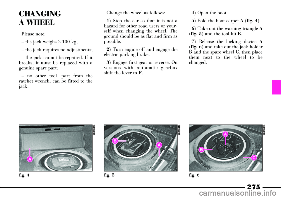
shift the lever to P.4) Open the boot.
5) Fold the boot carpet A(fig. 4).
6) Take out the warning triangle A
(fig. 5) and the tool kit B.
7) Release the locking device A
(fig. 6) and take out the jack holder
Band the spare wheel C, then place
them next to the wheel to be
changed.
fig. 4
L0A0033b
fig. 5
L0A0034b
fig. 6
L0A0035b
Page 277 of 386

276
8) Unscrew manually the jack han-
dle A(fig. 7) and remove it from the
container B.9) Open the tool bag and take out
the tools to be used (fig. 8):
1 – tow ring
2 – flat/cross-head screwdriver
3 – ratchet wrench
4 – ratchet wrench bush
5 – wheel bolt (for versions with
alloy rims)
6 – tool for removing the hub cap
(for versions with alloy rims)
7 – bush for unscrewing/screwing
the wheel bolts by hand8 – wrench for power steering re-
servoir cap screws
9 – wrench for actuating the sun-
roof in an emergency (where fitted)
10) On versions with alloy rims,
remove the press-fit wheel hub cap
A(fig. 9), pulling it by tool Bfitted
into C. On versions with steel rims,
remove the press-fit wheel cap A
(fig. 10).
fig. 8
L0A0326b
fig. 7
L0A0038b
fig. 9
L0A0327b
fig. 10
L0A0367b
Page 278 of 386

277
13) Position the jack under the car
near the wheel to be replaced in the
point shown on the panelling at
approximately 20 cm from the fend-
er edge, as shown in (fig. 12). 11) Place the bushing A(fig. 11)
for the wheel bolts on the ratchet
wrench B.
IMPORTANTThe ratchet wrench
must be used on one side to unscrew
and on the other side to screw.
12) Loosen the wheel bolts by
about one turn, then rock the car to
make it easier to remove the rim
from the wheel hub.Warn anyone nearby
that the car is about to be
lifted. They must stay
clear and not touch the car until
it is back on the ground.
fig. 12
L0A0039b
fig. 11
L0A0037b
Page 279 of 386

278
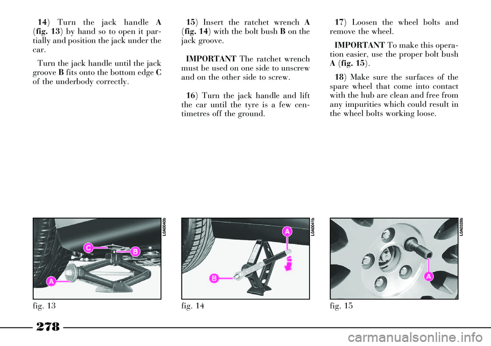
15) Insert the ratchet wrench A
(fig. 14) with the bolt bush Bon the
jack groove.
IMPORTANTThe ratchet wrench
must be used on one side to unscrew
and on the other side to screw.
16) Turn the jack handle and lift
the car until the tyre is a few cen-
timetres off the ground.17) Loosen the wheel bolts and
remove the wheel.
IMPORTANTTo make this opera-
tion easier, use the proper bolt bush
A(fig. 15).
18) Make sure the surfaces of the
spare wheel that come into contact
with the hub are clean and free from
any impurities which could result in
the wheel bolts working loose.
fig. 15
L0A0328b
fig. 13
L0A0040b
14) Turn the jack handle A
(fig. 13) by hand so to open it par-
tially and position the jack under the
car.
Turn the jack handle until the jack
groove Bfits onto the bottom edge C
of the underbody correctly.
fig. 14
L0A0041b
Page 280 of 386

279
19) On versions with alloy rims, to
make the wheel fitting easier, screw
the pin A(fig. 16), provided in the
tool kit, to the hub and then place
the wheel and tighten up the four
bolts in the free holes. Finally,
unscrew pin Aand screw the last
bolt.
On versions with steel rims, fit the
wheel making pin A(fig. 17) coin-
cide with one of the holes B.
IMPORTANTTo make bolt tight-
ening easier, use the proper bolt
bush A(fig. 15).Wheel bolts are specific
for the type of rim (alloy
or steel) fitted. Never use,
also if in an emergency, wheel
bolts for another type of rim.
When changing rims (alloy rims
instead of steel ones or vice
versa), also the whole wheel bolt
set shall be changed with other
bolts specific for the new type of
rim adopted.20) Lower the car and remove the
jack (fig. 18).
fig. 16
L0A0043b
fig. 17
L0A0366b
fig. 18
L0A0044b