engine Lancia Thesis 2007 Owner handbook (in English)
[x] Cancel search | Manufacturer: LANCIA, Model Year: 2007, Model line: Thesis, Model: Lancia Thesis 2007Pages: 386, PDF Size: 8.69 MB
Page 95 of 386
94
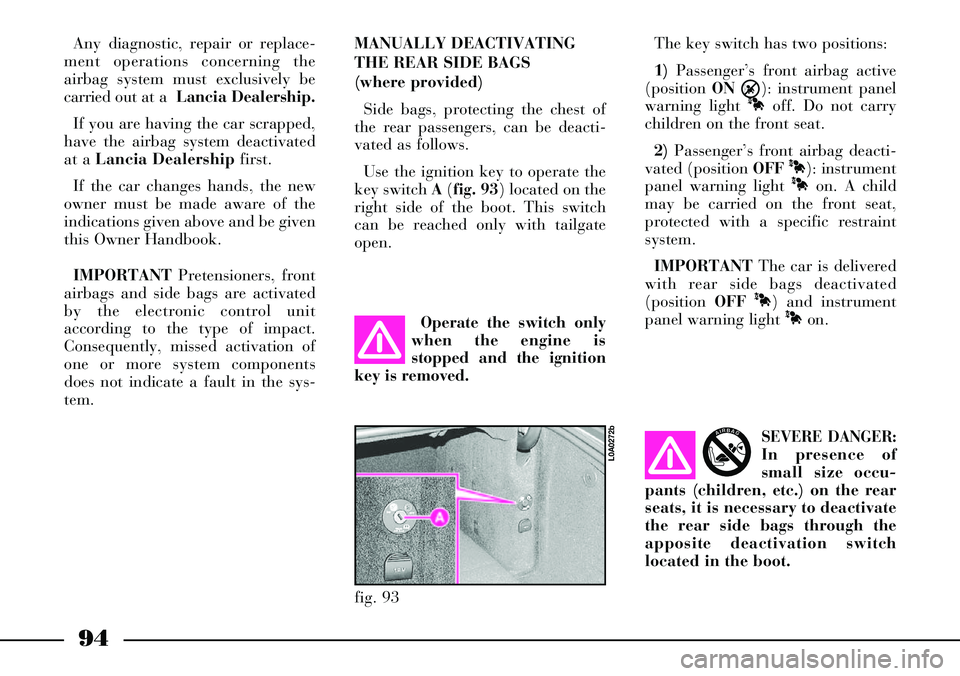
fig. 93
L0A0272b
Any diagnostic, repair or replace-
ment operations concerning the
airbag system must exclusively be
carried out at a Lancia Dealership.
If you are having the car scrapped,
have the airbag system deactivated
at a Lancia Dealershipfirst.
If the car changes hands, the new
owner must be made aware of the
indications given above and be given
this Owner Handbook.
IMPORTANTPretensioners, front
airbags and side bags are activated
by the electronic control unit
according to the type of impact.
Consequently, missed activation of
one or more system components
does not indicate a fault in the sys-
tem.MANUALLY DEACTIVATING
THE REAR SIDE BAGS
(where provided)
Side bags, protecting the chest of
the rear passengers, can be deacti-
vated as follows.
Use the ignition key to operate the
key switch A(fig. 93) located on the
right side of the boot. This switch
can be reached only with tailgate
open.The key switch has two positions:
1)Passenger’s front airbag active
(position ON
Õ): instrument panel
warning light
Àoff. Do not carry
children on the front seat.
2)Passenger’s front airbag deacti-
vated (position OFF
À): instrument
panel warning light
Àon. A child
may be carried on the front seat,
protected with a specific restraint
system.
IMPORTANTThe car is delivered
with rear side bags deactivated
(position OFF
À) and instrument
panel warning light
Àon.
Operate the switch only
when the engine is
stopped and the ignition
key is removed.
SEVERE DANGER:
In presence of
small size occu-
pants (children, etc.) on the rear
seats, it is necessary to deactivate
the rear side bags through the
apposite deactivation switch
located in the boot.
AIRBAG
Page 100 of 386
99
Twilight sensor
It is composed by an infrared led
sensor installed on the windscreen in
order to detect the changes of the
external light intensity of the car , as
a function of the light sensitivity set;
greater is the sensitivity, smaller is
the amount of external light neces-
sary to control the switching-on of
the exterior headlights.
It consists of two sensors: a global
sensor for evaluating environment
light intensity and a directional one
for evaluating light intensity in run-
ning direction in order to recognize
tunnels, dark road sections, etc.When ring Ais turned to AUTO
(automatic light switching on), and
the twilight sensor is malfunction-
ing, side/taillights and dipped beam
headlights are switched on regard-
less of the light intensity and the dis-
play on the instrument panel shows
the message “TWILIGHT SENSOR
FAULT – GO TO DEALER”.
Failure indication will stay on as
long as ring Ais turned to AUTO. In
this case it is recommended to deac-
tivate the automatic function and
switch on the lights manually; con-
tact a Lancia Dealershipas soon as
possible.Delayed light switching off
(“Follow me home” device)
This device allows the illumination
of the space in front of the car for a
length of time of 30 seconds (or a
multiple of 30) and is activated with
the ignition key at STOPor
removed.
This device is activated by pulling
towards the steering wheel and then
releasing the left-hand stalk within 2
minutes from when the engine is
turned off. At each operation of the
stalk, the staying on of the lights is
extended by 30 seconds, up to a
maximum of 210 seconds that corre-
spond to 7 stalk operations, then the
lights are switched off automatical-
ly.
Total set time (in seconds) is
shown on the instrument panel dis-
play for about 20 seconds.
Page 101 of 386
100
After activating the device, the set
time can be extended also within 2
minutes from when the engine is
turned off by pulling the stalk.
Keeping the stalk pulled for over 2
seconds will deactivate this function
with immediate light turning off as a
consequence.
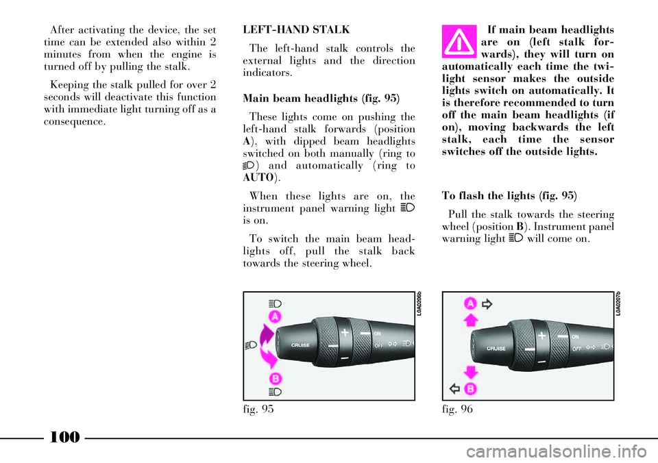
To flash the lights (fig. 95)
Pull the stalk towards the steering
wheel (position B). Instrument panel
warning light 1will come on. LEFT-HAND STALK
The left-hand stalk controls the
external lights and the direction
indicators.
Main beam headlights (fig. 95)
These lights come on pushing the
left-hand stalk forwards (position
A), with dipped beam headlights
switched on both manually (ring to
2) and automatically (ring to
AUTO).
When these lights are on, the
instrument panel warning light 1
is on.
To switch the main beam head-
lights off, pull the stalk back
towards the steering wheel.If main beam headlights
are on (left stalk for-
wards), they will turn on
automatically each time the twi-
light sensor makes the outside
lights switch on automatically. It
is therefore recommended to turn
off the main beam headlights (if
on), moving backwards the left
stalk, each time the sensor
switches off the outside lights.
fig. 95
L0A0206b
fig. 96
L0A0207b
Page 104 of 386
103
Operating the windscreen washer
with the rain sensor activated (stalk
at position 1) the normal washing
cycle is performed at the end of
which the rain sensor resumes its
normal automatic function.
The rain sensor is switched off
when the key is turned to STOP. It
will not come on again at the follow-
ing engine start-up (key at MAR)
even if the stalk is at position 1. This
will avoid accidental activation when
starting the engine that could result
in dangerous situations (e.g. manual
windscreen washing, wiper blades
sticking due to ice and risk of dam-
aging the windscreen wiper motor).
In this case to activate the rain sen-
sor, just take the stalk to position 0
or2and then to 1again, or change
sensitivity (increase or decrease)
through knurled ring A. When the rain sensor is again acti-
vated in this way, at least one wind-
screen wiper stroke occurs, even if
the windscreen is dry, to signal the
occurred re-activation.
The rain sensor is located behind
the driving mirror in contact with
the windscreen and inside the area
cleaned by the wiper and it controls
an electronic control unit which in
turns controls the wiper motor.
At starting, the rain sensor auto-
matically provides to stabilize at
about 40°C temperature to elimi-
nate, from the control surface, the
possible condensate and to prevent
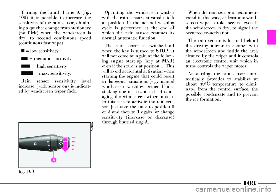
the ice formation. Turning the knurled ring A(fig.
100) it is possible to increase the
sensitivity of the rain sensor, obtain-
ing a quicker change from stationary
(no flick) when the windscreen is
dry, to second continuous speed
(continuous fast wipe):
■= low sensitivity
■■= medium sensitivity
■■■= high sensitivity
■■■■= max. sensitivity.
Rain sensor sensitivity level
increase (with sensor on) is indicat-
ed by windscreen wiper flick.
fig. 100
L0A0205b
Page 106 of 386
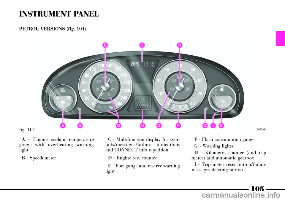
INSTRUMENT PANEL
PETROL VERSIONS (fig. 101)
A- Engine coolant temperature
gauge with overheating warning
light
B- SpeedometerC- Multifunction display for sym-
bols/messages/failure indications
and CONNECT info repetition
D- Engine rev. counter
E- Fuel gauge and reserve warning
lightF- Flash consumption gauge
G- Warning lights
H- Kilometre counter (and trip
meter) and automatic gearbox
I- Trip meter reset button/failure
messages deleting button
fig. 101L0A0230b
105
Page 107 of 386
106
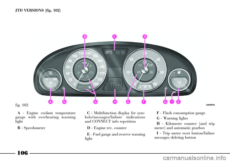
JTD VERSIONS (fig. 102)
fig. 102L0A0231b
A- Engine coolant temperature
gauge with overheating warning
light
B- SpeedometerC- Multifunction display for sym-
bols/messages/failure indications
and CONNECT info repetition
D - Engine rev. counter
E- Fuel gauge and reserve warning
lightF- Flash consumption gauge
G- Warning lights
H- Kilometre counter (and trip
meter) and automatic gearbox
I- Trip meter reset button/failure
messages deleting button
Page 108 of 386

107
INSTRUMENTS
SPEEDOMETER (fig. 103)
The speedometer shows the car
speed expressed in kilometres per
hour (km/h) and starts signalling
the speed when the car speed
exceeds approx. 4 km/h (see the
indications given in paragraph “At
the filling station").REV COUNTER (fig. 104)
If the needle is in the hazard sector
(the section with red lines) it shows
that the engine is over-revving. Do
not travel with the needle in this sec-
tor.
When the engine is idling, the rev
counter may show a gradual or sud-
den increase in engine speed,
according to the case. This is normal
and indicates the operation of the
climate control compressor or fans,
etc. In particular, a gradual varia-
tion in engine revolution speed safe-
guards battery charge.IMPORTANTThe hazard sectors
can present different widths and dif-
ferent full scale values according to
the various car versions.
IMPORTANTThe electronic injec-
tion control system will progressive-
ly cut off the flow of fuel when the
engine is over-revving and the
engine will consequently lose power.
fig. 103
L0A0232b
fig. 104
L0A0233b
Page 109 of 386
108
fig. 106
L0A0236b
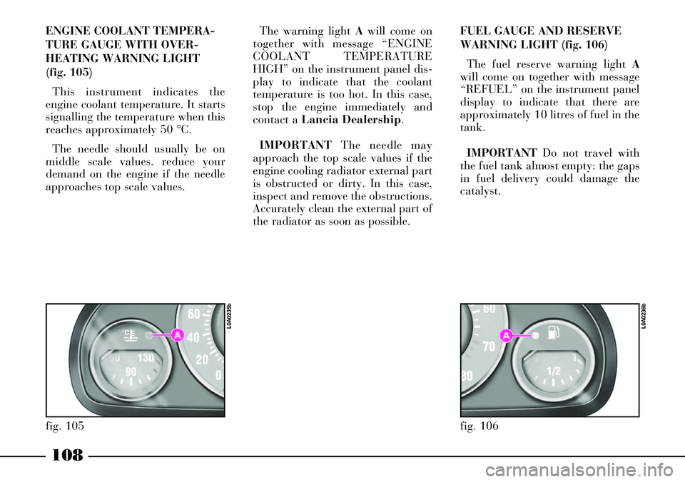
ENGINE COOLANT TEMPERA-
TURE GAUGE WITH OVER-
HEATING WARNING LIGHT
(fig. 105)
This instrument indicates the
engine coolant temperature. It starts
signalling the temperature when this
reaches approximately 50 °C.
The needle should usually be on
middle scale values. reduce your
demand on the engine if the needle
approaches top scale values.The warning light Awill come on
together with message “ENGINE
COOLANT TEMPERATURE
HIGH” on the instrument panel dis-
play to indicate that the coolant
temperature is too hot. In this case,
stop the engine immediately and
contact a Lancia Dealership.
IMPORTANTThe needle may
approach the top scale values if the
engine cooling radiator external part
is obstructed or dirty. In this case,
inspect and remove the obstructions.
Accurately clean the external part of
the radiator as soon as possible.FUEL GAUGE AND RESERVE
WARNING LIGHT (fig. 106)
The fuel reserve warning light A
will come on together with message
“REFUEL” on the instrument panel
display to indicate that there are
approximately 10 litres of fuel in the
tank.
IMPORTANTDo not travel with
the fuel tank almost empty: the gaps
in fuel delivery could damage the
catalyst.
fig. 105
L0A0235b
Page 110 of 386

109
IMPORTANTRefuelling shall
always be performed with engine off
and ignition key to STOP. If the
engine is off but the key is to MAR,
a wrong fuel level could temporarily
be indicated. This is due to the inter-
nal system control logic and cannot
be considered as a system malfunc-
tioning.FLASH CONSUMPTION GAUGE
(fig. 107)
Gauge Ashows the flash consump-
tion: to prevent excessively variable
values the gauge shows the average
consumption of the last minutes of
travel expressed in l/100 km (litres
per 100 km).
This is helpful for the driver for
learning the fuel consumption in
relation to the driving style.The gauge needle has the following
position:
– value 0 l/100 km with car sta-
tionary
– near value 2 l/100 km when the
car speed is between 4 and 20 km/h
and when releasing the accelerator
pedal during driving
– actual consumption value
(between 2 and 20 l/100 km) for
speeds exceeding 20 km/h.
fig. 107
L0A0234b
Page 112 of 386
111
Driver’s aiding system
information
– Cruise Control info
– Radar Cruise Control info
The language used for indicating
failures and messages on the multi-
function display is the same as the
CONNECT language (where it is
possible to set it). Car conditions
– Scheduled servicing
– Engine oil level (JTD versions
only)
– Instrument dimmer
– Failure message display
– Display of warning messages with
corresponding symbols (e.g.
“WARNING ICE HAZARD”, “ASR
OFF”, etc.).CONNECT information
Information managed by CONNECT:
– AUDIO function info
– NAVIGATOR info (symbol repe-
tition)
– TELEPHONE function info
– VOICE BOX info
– SMS messages reception.