sensor Lancia Voyager 2013 Owner handbook (in English)
[x] Cancel search | Manufacturer: LANCIA, Model Year: 2013, Model line: Voyager, Model: Lancia Voyager 2013Pages: 360, PDF Size: 4.21 MB
Page 139 of 360
WARNING!
Electronic Speed Control can be
dangerous where the system cannot
maintain a constant speed. Your ve-
hicle could go too fast for the con-
ditions, and you could lose control
and have an accident. Do not use
Electronic Speed Control in heavy
traffic or on roads that are winding,
icy, snow-covered or slippery.
PARKSENSE® REAR
PARK ASSIST (for
versions/markets, where
provided)
The ParkSense® Rear Park Assist
system provides visual and audible
indications of the distance between
the rear fascia and a detected obstacle
when backing up, e.g. during a park-
ing maneuver. Refer to ParkSense®
System Usage Precautions for limita-
tions of this system and recommenda-
tions. ParkSense® will retain the last sys-
tem state (enabled or disabled) from
the last ignition cycle when the igni-
tion is changed to the ON/RUN posi-
tion.
ParkSense® can be active only when
the shift lever is in REVERSE. If
ParkSense® is enabled at this shift
lever position, the system will remain
active until the vehicle speed is in-
creased to approximately 18 km/h or
above. The system will become active
again if the vehicle speed is decreased
to speeds less than approximately
16 km/h.
PARKSENSE® SENSORS
The four ParkSense® sensors, located
in the rear fascia/bumper, monitor the
area behind the vehicle that is within
the sensors’ field of view. The sensors
can detect obstacles from approxi-
mately 30 cm up to 200 cm from the
rear fascia/bumper in the horizontal
direction, depending on the location,
type and orientation of the obstacle.PARKSENSE® WARNING
DISPLAY
The ParkSense® Warning screen will
only be displayed if Sound and Dis-
play is selected from the Customer-
Programmable Features section of the
Electronic Vehicle Information Center
(EVIC). Refer to “Electronic Vehicle
Information Center (EVIC)/Personal
Settings (Customer- Programmable
Features)” in “Understanding Your
Instrument Panel” for further infor-
mation.
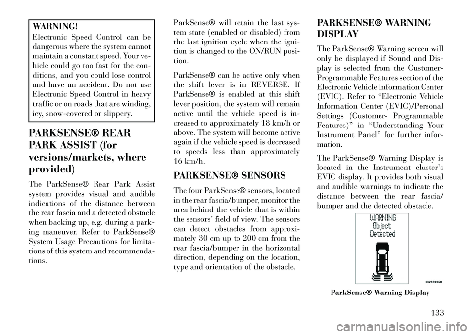
The ParkSense® Warning Display is
located in the Instrument cluster’s
EVIC display. It provides both visual
and audible warnings to indicate the
distance between the rear fascia/
bumper and the detected obstacle.
ParkSense® Warning Display
133
Page 141 of 360
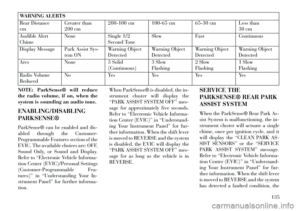
WARNING ALERTS
Rear Distance
cmGreater than
200 cm200-100 cm 100-65 cm 65-30 cm Less than
30 cm
Audible Alert
Chime None
Single 1/2
Second Tone Slow
FastContinuous
Display Message Park Assist Sys- tem ONWarning Object
DetectedWarning Object
DetectedWarning Object
DetectedWarning Object
Detected
Arcs None3 Solid
(Continuous) 3 Slow
Flashing2 Slow
Flashing1 Slow
Flashing
Radio Volume
Reduced No
YesYesYesYes
NOTE: ParkSense® will reduce
the radio volume, if on, when the
system is sounding an audio tone.
ENABLING/DISABLING
PARKSENSE®
ParkSense® can be enabled and dis-
abled through the Customer-
Programmable Features section of the
EVIC. The available choices are: OFF,
Sound Only, or Sound and Display.
Refer to “Electronic Vehicle Informa-
tion Center (EVIC)/Personal Settings
(Customer-Programmable Fea-
tures)” in “Understanding Your In-
strument Panel” for further informa-
tion. When ParkSense® is disabled, the in-
strument cluster will display the
“PARK ASSIST SYSTEM OFF” mes-
sage for approximately five seconds.
Refer to “Electronic Vehicle Informa-
tion Center (EVIC)” in “Understand-
ing Your Instrument Panel” for fur-
ther information. When the shift lever
is moved to REVERSE and the system
is disabled, the EVIC will display the
“PARK ASSIST SYSTEM OFF” mes-
sage for as long as the vehicle is in
REVERSE.
SERVICE THE
PARKSENSE® REAR PARK
ASSIST SYSTEM
When the ParkSense® Rear Park As-
sist System is malfunctioning, the in-
strument cluster will actuate a single
chime, once per ignition cycle, and it
will display the “CLEAN PARK AS-
SIST SENSORS” or the “SERVICE
PARK ASSIST SYSTEM” message.
Refer to “Electronic Vehicle Informa-
tion Center (EVIC)” in “Understand-
ing Your Instrument Panel” for fur-
ther information. When the shift lever
is moved to REVERSE and the system
has detected a faulted condition, the
135
Page 142 of 360
EVIC will display the “CLEAN PARK
ASSIST SENSORS” or the “SER-
VICE PARK ASSIST SYSTEM” mes-
sage for as long as the vehicle is in
REVERSE. Under this condition,
ParkSense® will not operate.
If “CLEAN PARK ASSIST SEN-
SORS” appears in the EVIC after
making sure the rear fascia/bumper is
free from snow, ice, mud, dirt or other
obstruction, see your authorized
dealer.
If “SERVICE PARK ASSIST SYS-
TEM” appears in the EVIC, see your
authorized dealer.
CLEANING THE
PARKSENSE® SYSTEM
Clean the ParkSense® sensors with
water, car wash soap and a soft cloth.
Do not use rough or hard cloths. Do
not scratch or poke the sensors. Oth-
erwise, you could damage the sensors.PARKSENSE® SYSTEM
USAGE PRECAUTIONS
NOTE:
Ensure that the rear bumper is
free of snow, ice, mud, dirt and
debris to keep the ParkSense®
system operating properly.
Jackhammers, large trucks, and other vibrations could affect the
performance of ParkSense®.
When you turn ParkSense® off, the instrument cluster will dis-
play “PARK ASSIST SYSTEM
OFF.” Furthermore, once you
turn ParkSense® off, it remains
off until you turn it on again,
even if you cycle the ignition key.
When you move the shift lever to the REVERSE position and
ParkSense® is turned off, the
EVIC will display “PARK AS-
SIST SYSTEM OFF” message for
as long as the vehicle is in
REVERSE. ParkSense®, when on, will re-
duce the radio volume when it is
sounding a tone.
Clean the ParkSense® sensors regularly, taking care not to
scratch or damage them. The
sensors must not be covered
with ice, snow, slush, mud, dirt
or debris. Failure to do so can
result in the system not working
properly. The ParkSense® sys-
tem might not detect an obstacle
behind the fascia/bumper, or it
could provide a false indication
that an obstacle is behind the
fascia/bumper.
Objects such as bicycle carriers, trailer hitches, etc., must not be
placed within 30 cm from the
rear fascia/bumper while driv-
ing the vehicle. Failure to do so
can result in the system misin-
terpreting a close object as a
sensor problem, causing the
“SERVICE PARK ASSIST SYS-
TEM” message to be displayed
in the EVIC.
136
Page 143 of 360

On vehicles equipped with atailgate, ParkSense® should be
disabled when the tailgate is in
the lowered or open position
and the vehicle is in REVERSE.
A lowered tailgate could provide
a false indication that an ob-
stacle is behind the vehicle.CAUTION!
ParkSense® is only a parking aidand it is unable to recognize every
obstacle, including small ob-
stacles. Parking curbs might be
temporarily detected or not de-
tected at all. Obstacles located
above or below the sensors will
not be detected when they are in
close proximity.
The vehicle must be driven slowly when using ParkSense® in order
to be able to stop in time when an
obstacle is detected. It is recom-
mended that the driver looks over
his/her shoulder when using
ParkSense®.
WARNING!
Drivers must be careful whenbacking up even when using the
Rear Park Assist system. Always
check carefully behind your ve-
hicle, look behind you, and be
sure to check for pedestrians, ani-
mals, other vehicles, obstruc-
tions, and blind spots before
backing up. You are responsible
for safety and must continue to
pay attention to your surround-
ings. Failure to do so can result in
serious injury or death.
(Continued)
WARNING!(Continued)
Before using the Rear Park Assist system, it is strongly recom-
mended that the ball mount and
hitch ball assembly is discon-
nected from the vehicle when the
vehicle is not used for towing.
Failure to do so can result in in-
jury or damage to vehicles or ob-
stacles because the hitch ball will
be much closer to the obstacle
than the rear fascia when the
loudspeaker sounds the continu-
ous tone. Also, the sensors could
detect the ball mount and hitch
ball assembly, depending on its
size and shape, giving a false in-
dication that an obstacle is be-
hind the vehicle.
137
Page 177 of 360

illuminated. This sequence will con-
tinue upon subsequent vehicle start-
ups as long as the malfunction exists.
When the malfunction indicator is il-
luminated, the system may not be
able to detect or signal low tire pres-
sure as intended. TPMS malfunctions
may occur for a variety of reasons,
including the installation of replace-
ment or alternate tires or wheels on
the vehicle that prevent the TPMS
from functioning properly. Always
check the TPMS malfunction telltale
after replacing one or more tires or
wheels on your vehicle, to ensure that
the replacement or alternate tires and
wheels allow the TPMS to continue to
function properly.CAUTION!
The TPMS has been optimized for
the original equipment tires and
wheels. TPMS pressures and warn-
ing have been established for the
tire size equipped on your vehicle.
Undesirable system operation or
sensor damage may result when us-
ing replacement equipment that is(Continued)
CAUTION!(Continued)
not of the same size, type, and/or
style. Aftermarket wheels can cause
sensor damage. Do not use tire seal-
ant from a can or balance beads if
your vehicle is equipped with a
TPMS, as damage to the sensors
may result.
9. Malfunction Indicator Light
(MIL) The Malfunction Indicator
Light (MIL) is part of an on-
board diagnostic system,
called OBD, that monitors engine and
automatic transmission control sys-
tems. The light will illuminate when
the key is in the ON/RUN position,
before engine start. If the bulb does
not come on when turning the key
from OFF to ON/RUN, have the con-
dition checked promptly.
Certain conditions, such as a loose or
missing gas cap, poor fuel quality,
etc., may illuminate the MIL after en-
gine start. The vehicle should be ser-
viced if the light stays on through
several of your typical driving cycles. In most situations, the vehicle will
drive normally and will not require
towing.
CAUTION!
Prolonged driving with the MIL on
could cause damage to the engine
control system. It also could affect
fuel economy and drivability. If the
MIL is flashing, severe catalytic
converter damage and power loss
will soon occur. Immediate service
is required.WARNING!
A malfunctioning catalytic con-
verter, as referenced above, can
reach higher temperatures than in
normal operating conditions. This
can cause a fire if you drive slowly
or park over flammable substances
such as dry plants, wood, card-
board, etc. This could result in
death or serious injury to the driver,
occupants or others.
171
Page 186 of 360
Five Second Unstored Messages
When the appropriate conditions oc-
cur, this type of message takes control
of the main display area for five sec-
onds and then returns to the previous
screen. Examples of this message type
are "Memory System Unavailable -
Not in Park" and "Automatic High
Beams On".
The Reconfigurable Telltales section
is divided into the white telltales area
on the right, amber telltales in the
middle, and red telltales on the left.
When the appropriate conditions ex-
ist, the EVIC displays the following
messages:
Key in ignition
Ignition or Accessory On
Wrong Key
Damaged Key
Key not programmed
Vehicle Not in Park
Key Left Vehicle
Key Not Detected Press Brake Pedal and Push Button
to Start
Liftgate Ajar (chime will sound when vehicle starts moving)
Low Tire Pressure
Service TPM System (refer to “Tire Pressure Monitoring System” in
“Starting And Operating”)
Turn Signal On
RKE Battery Low
Service Keyless System
LOW WASHER FLUID
Oil Change Required
Check Gascap
Left Front Turn Signal Lamp Out
Left Rear Turn Signal Lamp Out
Right Front Turn Signal Lamp Out
Right Rear Turn Signal Lamp Out
Park Assist Disabled
Service Park Assist System Personal Settings Not Available —
Vehicle Not in Park
Blind Spot System Off — This mes- sage is displayed when the ignition
is turned to ON to indicate the Blind
Spot System has been turned off.
Blind Spot System Not Available — This message is displayed to indi-
cate the Blind Spot Monitor (BSM)
system is temporarily unavailable
due to sensor blockage, electronic
interference, or other "temporary"
conditions. When this message is
displayed both outside rear view
icons will be illuminated. If elec-
tronic interference is present, the
BSM system will illuminate the icon
only on the side of interference as
long as interference is present.
Service Blind Spot System — This message is displayed to indicate the
Blind Spot Monitor (BSM) system is
permanently unavailable. The
driver will receive an EVIC mes-
sage and the BSM display warning
in both mirrors will be permanently
illuminated. If this message is pres-
ent see an authorized dealer.
180
Page 199 of 360
NOTE: If your vehicle has experi-
enced any damage in the area
where the sensor is located, even if
the fascia is not damaged, the sen-
sor may have become misaligned.
Take your vehicle to an authorized
dealer to verify sensor alignment.
Having a sensor that is misaligned
will result in the BSM not operat-
ing to specification.
Calibrate Compass (for
versions/markets, where
provided)
Refer to “Compass Display” for more
information.
Compass Variance (for
versions/markets, where
provided)
Refer to “Compass Display” for more
information.
Turn Menu Off
Press and release SELECT to turn the
menu off.SOUND SYSTEMS
Refer to your Sound Systems Booklet.
NAVIGATION SYSTEM
(for versions/markets,
where provided)
Refer to your Uconnect Touch™ User
Manual.
iPod®/USB/MP3
CONTROL (for
versions/markets, where
equipped)
NOTE: This section is for sales
code RES and REQ/REL/RET ra-
dios only with Uconnect™. For
sales code RBZ/RHB, RHR, RHP,
RHW or RB2 touch-screen radio
iPod®/USB/MP3 control feature,
refer to the separate RBZ/RHB,
RHR, RHP, RHW or RB2 User's
Manual. iPod®/USB/MP3 control
is available only for versions/
markets, where provided with
these radios.This feature allows an iPod® or exter-
nal USB device to be plugged into the
USB port, located in the glove com-
partment.
iPod® control supports Mini, 4G,
Photo, Nano, 5G iPod® and iPhone®
devices. Some iPod® software ver-
sions may not fully support the iPod®
control features. Please visit Apple’s
website for software updates.
NOTE:
If the radio has a USB port, refer
to the appropriate Uconnect™
Multimedia radio User’s Manual
for iPod® or external USB de-
vice support capability.
Connecting an iPod® or con- sumer electronic audio device to
the AUX port located in the ra-
dio faceplate, plays media, but
does not use the iPod® /MP3
control feature to control the
connected device.
193
Page 251 of 360
WARNING!
The BAS cannot prevent thenatural laws of physics from act-
ing on the vehicle, nor can it in-
crease the traction afforded by
prevailing road conditions.
The BAS cannot prevent colli-
sions, including those resulting
from excessive speed in turns,
driving on very slippery surfaces,
or hydroplaning.
The capabilities of a BAS- equipped vehicle must never be
exploited in a reckless or danger-
ous manner which could jeopar-
dize the user's safety or the safety
of others. ELECTRONIC STABILITY
CONTROL (ESC)
The Electronic Stability Control (ESC)
enhances directional control and sta-
bility of the vehicle under various driv-
ing conditions. ESC corrects for over/
under steering of the vehicle by
applying the brake of the appropriate
wheel to assist in counteracting the
over/under steer condition. Engine
power may also be reduced to help the
vehicle maintain the desired path.ESC uses sensors in the vehicle to
determine the vehicle path intended
by the driver and compares it to the
actual path of the vehicle. When the
actual path does not match the in-
tended path, ESC applies the brake of
the appropriate wheel to assist in
counteracting the oversteer or under-
steer condition.
Oversteer - when the vehicle is
turning more than appropriate for
the steering wheel position.
Understeer - when the vehicle is turning less than appropriate for
the steering wheel position.
WARNING!
The Electronic Stability Control
(ESC) cannot prevent the natural
laws of physics from acting on the
vehicle, nor can it increase the trac-
tion afforded by prevailing road
conditions. ESC cannot prevent ac-
cidents, including those resulting
from excessive speed in turns, driv-
ing on very slippery surfaces, or
hydroplaning. ESC also cannot
prevent accidents resulting from
loss of vehicle control due to inap-
propriate driver input for the con-
ditions. Only a safe, attentive, and
skillful driver can prevent acci-
dents. The capabilities of an ESC
equipped vehicle must never be ex-
ploited in a reckless or dangerous
manner which could jeopardize the
user’s safety or the safety of others.WARNING!
In partial ESC mode, the engine
power reduction feature of ESC is
disabled. Therefore, enhanced ve-
hicle stability offered by the ESC
system is reduced.
245
Page 268 of 360

For example, your vehicle may have a
recommended cold (parked for more
than three hours) tire pressure of 2.4
BAR. If the ambient temperature is
20°C and the measured tire pressure
is 2.1 BAR, a temperature drop to
7°C will decrease the tire pressure to
approximately 1.8 BAR. This tire
pressure is sufficiently low enough to
turn on the “Tire Pressure Monitoring
Telltale Light.” Driving the vehicle
may cause the tire pressure to rise to
approximately 2.1 BAR, but the “Tire
Pressure Monitoring Telltale Light”
will still be on. In this situation, the
“Tire Pressure Monitoring Telltale
Light” will turn off only after the tires
have been inflated to the vehicle’s rec-
ommended cold tire pressure value.
CAUTION!
The TPMS has been optimizedfor the original equipment tires
and wheels. TPMS pressures have
been established for the tire size
equipped on your vehicle. Unde-
sirable system operation or sensor
damage may result when using
replacement equipment that is
not of the same size, type, and/or
style. Aftermarket wheels can
cause sensor damage. Do not use
aftermarket sealants or balance
beads if your vehicle is equipped
with a TPMS, as damage to the
sensors may result.
After inspecting or adjusting the tire pressure always reinstall the
valve stem cap. This will prevent
moisture and dirt from entering
the valve stem, which could dam-
age the TPMS sensor.
NOTE:
The TPMS is not intended to re- place normal tire care and
maintenance, or to provide
warning of a tire failure or con-
dition. The TPMS should not be used as
a tire pressure gauge while ad-
justing your tire pressure.
Driving on a significantly under- inflated tire causes the tire to
overheat and can lead to tire
failure. Under-inflation also re-
duces fuel efficiency and tire
tread life, and may affect the ve-
hicle’s handling and stopping
ability.
The TPMS is not a substitute for proper tire maintenance, and it
is the driver's responsibility to
maintain correct tire pressure,
using an accurate tire pressure
gage, even if under-inflation has
not reached the level to trigger
illumination of the “Tire Pres-
sure Monitoring Telltale Light.”
Seasonal temperature changes will affect tire pressure, and the
TPMS will monitor the actual
tire pressure in the tire.
262
Page 269 of 360

BASE SYSTEMThe TPMS uses wireless technology
with wheel rim mounted electronic sen-
sors to monitor tire pressure levels. Sen-
sors, mounted to each wheel as part of
the valve stem, transmit tire pressure
readings to the Receiver Module.NOTE: It is particularly impor-
tant for you to check the tire pres-
sure in all of your tires regularly
and to maintain the proper pres-
sure.
The Basic TPMS consists of the fol-
lowing components:
Receiver Module
Four Tire Pressure MonitoringSensors
TPMS Telltale Warning Light
Tire Pressure Monitoring Low
Tire Pressure Warnings
The “Tire Pressure Moni-
toring Telltale Light” will
illuminate in the instru-
ment cluster, an “Inflate
Tire to XX” message and a "TIRE LOW PRESSURE" message will dis-
play in the instrument cluster, and an
audible chime will be activated when
one or more of the four active road tire
pressures are low. The recommended
cold placard pressure inflation value
is the pressure value displayed in the
"Inflate Tire to XX" message dis-
played in the EVIC. Should this occur,
you should stop as soon as possible,
check the inflation pressure of each
tire on your vehicle, and inflate each
tire to the vehicle's recommended cold
tire pressure value (located on the
placard on the driver's-side B-Pillar).
The system will automatically update
and the “Tire Pressure Monitoring
Telltale Light” will extinguish once
the updated tire pressures have been
received.
NOTE: The vehicle may need to
be driven for up to 20 minutes
above 24 km/h to receive this in-
formation.
The “Tire Pressure Monitoring Tell-
tale Light” will flash on and off for 75
seconds, and remain on solid when a
system fault is detected. The system
fault will also sound a chime. If the
ignition switch is cycled, this se-
quence will repeat, providing the sys-
tem fault still exists. The “Tire Pres-
sure Monitoring Telltale Light” will
turn off when the fault condition no
longer exists. A system fault can occur
with any of the following scenarios:
1. Jamming due to electronic devices
or driving next to facilities emitting
the same radio frequencies as the
TPMS sensors.
2. Installing some form of aftermar-
ket window tinting that affects radio
wave signals.
3. Accumulation of excessive snow
and/or ice around the wheels or wheel
housings.
4. Using tire chains on the vehicle.
5. Using wheels/tires not equipped
with TPMS sensors.
263