weight Lancia Voyager 2013 Owner handbook (in English)
[x] Cancel search | Manufacturer: LANCIA, Model Year: 2013, Model line: Voyager, Model: Lancia Voyager 2013Pages: 360, PDF Size: 4.21 MB
Page 61 of 360

Mass Group Seating Position (or other site)Front Passenger Rear Outboard Rear Center Intermediate OutboardIntermediate
Center
Group 0 - Up to
10 kg X
UUUX
Group 0+ - Up to
13 kg X
UUUX
Group 1 - 9 to
18 kg X
UUUX
Group II - 15 to
25 kg X
UUUX
Group III - 22 to
36 kg X
UUUX
Key of letters used in the table above:
U = Suitable for “universal” cat- egory restraints approved for use in
this age/weight group.
UF = Suitable for forward-facing “universal” category restraints ap-
proved for use in this mass group. L = Suitable for particular child
restraints given on attached list.
These restraints may be of the “spe-
cific vehicle”, “restricted” or
“semi-universal” categories.
B = Built-in restraint approved for the age/weight group. X = Seat position not suitable for
children in this age/weight group.
55
Page 64 of 360

Infants And Small Children
Safety experts recommend that chil-
dren ride rearward-facing in the ve-
hicle until they are two years old or
until they reach either the height or
weight limit of their rear facing child
safety seat. Two types of child re-
straints can be used rearward-facing:
infant carriers and convertible child
seats.
The infant carrier is only used
rearward-facing in the vehicle. It is
recommended for children from birth
until they reach the weight or height
limit of the infant carrier. Convertible
child seats can be used either
rearward-facing or forward-facing in
the vehicle. Convertible child seats of-
ten have a higher weight limit in the
rearward-facing direction than infant
carriers do, so they can be used
rearward-facing by children who
have outgrown their infant carrier but
are still less than at least two years
old. Children should remain
rearward-facing until they reach the
highest weight or height allowed by
their convertible child seat. Both
types of child restraints are held in thevehicle by the lap/shoulder belt or the
ISOFIX child restraint anchor system.
Refer to “ISOFIX — Child Seat An-
chorage System”.
WARNING!
Rearward-facing child seats must
never be used in the front seat of a
vehicle with a front passenger air
bag. An air bag deployment could
cause severe injury or death to in-
fants in this position.
Older Children And Child
Restraints
Children who are two years old or who
have outgrown their rear-facing con-
vertible child seat can ride forward-
facing in the vehicle. Forward-facing
child seats and convertible child seats
used in the forward-facing direction
are for children who are over two
years old or who have outgrown the
rear-facing weight or height limit of
their rear-facing convertible child
seat. Children should remain in a
forward-facing child seat with a har-
ness for as long as possible, up to the
highest weight or height allowed by the child seat. These child seats are
also held in the vehicle by the lap/
shoulder belt or the ISOFIX child re-
straint anchorage system. Refer to
“ISOFIX — Child Seat Anchorage
System”.
All children whose weight or height is
above the forward-facing limit for the
child seat should use a belt-
positioning booster seat until the ve-
hicle’s seat belts fit properly. If the
child cannot sit with knees bent over
the vehicle's seat cushion while the
child's back is against the seatback,
they should use a belt-positioning
booster seat. The child and belt-
positioning booster seat are held in
the vehicle by the lap/shoulder belt.
Children Too Large For Booster
Seats
Children who are large enough to
wear the shoulder belt comfortably,
and whose legs are long enough to
bend over the front of the seat when
their back is against the seatback,
should use the lap/shoulder belt in a
rear seat.
58
Page 65 of 360

Make sure that the child is uprightin the seat.
The lap portion should be low on the hips and as snug as possible.
Check belt fit periodically. A child's squirming or slouching can move
the belt out of position.
If the shoulder belt contacts the face or neck, move the child closer
to the center of the vehicle. If this
doesn't help, move the child to the
center rear seating position and use
both the lap and shoulder belt.
Never allow a child to put the
shoulder belt under an arm or be-
hind their back.WARNING!
Improper installation can lead tofailure of an infant or child re-
straint. It could come loose in a
collision. The child could be
badly injured or killed. Follow
the manufacturer's directions ex-
actly when installing an infant or
child restraint.
(Continued)
WARNING!(Continued)
A rearward-facing child restraint should only be used in a rear seat.
A rearward-facing child restraint
in the front seat may be struck by
a deploying passenger air bag
which may cause severe or fatal
injury to the infant.
Here are some tips on getting the
most out of your child restraint:
Before buying any restraint system, make sure that it has a label certi-
fying that it meets all applicable
Safety Standards. LANCIA also
recommends that you make sure
that you can install the child re-
straint in the vehicle where you will
use it, before you buy it.
The restraint must be appropriate for your child's weight and height.
Check the label on the restraint for
weight and height limits.
Carefully follow the instructions that come with the restraint. If you
install the restraint improperly, it
may not work when you need it. Passenger seat belts are equipped
with an Automatic Locking Retrac-
tor (ALR) designed to keep the lap
portion tight around the child re-
straint so that it is not necessary to
use a locking clip. In seating posi-
tions that are equipped with an
ALR retractor, it will make a ratch-
eting noise after all the webbing is
extracted and allowed to return
back. For additional information,
refer to “Automatic Locking
Mode”.
In the rear seat, you may have trouble tightening the lap/shoulder
belt on the child restraint because
the buckle or latch plate is too close
to the belt path opening on the re-
straint. Disconnect the latch plate
from the buckle and twist the short
buckle end of the belt several times
to shorten it. Insert the latch plate
into the buckle with the release but-
ton facing out.
If the belt still can't be tightened, or if pulling and pushing on the re-
straint loosens the belt, disconnect
the latch plate from the buckle,
59
Page 125 of 360
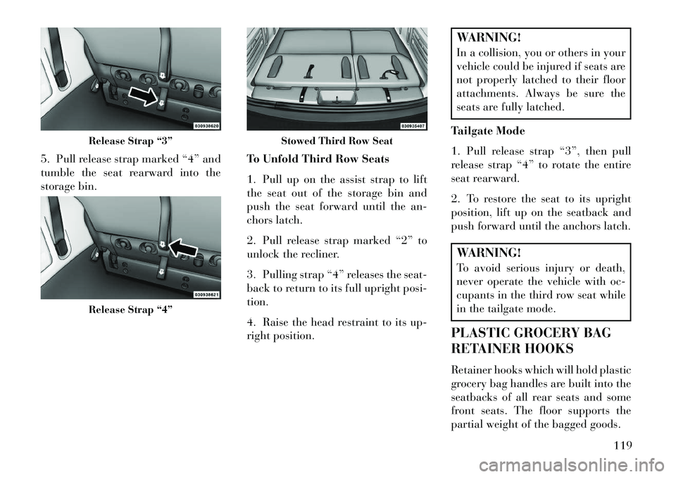
5. Pull release strap marked “4” and
tumble the seat rearward into the
storage bin.To Unfold Third Row Seats
1. Pull up on the assist strap to lift
the seat out of the storage bin and
push the seat forward until the an-
chors latch.
2. Pull release strap marked “2” to
unlock the recliner.
3. Pulling strap “4” releases the seat-
back to return to its full upright posi-
tion.
4. Raise the head restraint to its up-
right position.
WARNING!
In a collision, you or others in your
vehicle could be injured if seats are
not properly latched to their floor
attachments. Always be sure the
seats are fully latched.
Tailgate Mode
1. Pull release strap “3”, then pull
release strap “4” to rotate the entire
seat rearward.
2. To restore the seat to its upright
position, lift up on the seatback and
push forward until the anchors latch.WARNING!
To avoid serious injury or death,
never operate the vehicle with oc-
cupants in the third row seat while
in the tailgate mode.
PLASTIC GROCERY BAG
RETAINER HOOKS
Retainer hooks which will hold plastic
grocery bag handles are built into the
seatbacks of all rear seats and some
front seats. The floor supports the
partial weight of the bagged goods.
Release Strap “3”Release Strap “4”
Stowed Third Row Seat
119
Page 133 of 360
NOTE: This system will not acti-
vate until the vehicle is at, or
above, 40 km/h.
HEADLIGHT LEVELING
SYSTEM (for versions/
markets, where provided)Your vehicle may be
equipped with a headlight
leveling system. This sys-
tem allows the driver to
maintain proper headlight beam posi-
tion with the road surface regardless
of vehicle load. The control switch is
located on the instrument panel next
to the dimmer control.
To operate, rotate the control switch
until the appropriate number, which
corresponds to the load listed on the
chart, aligns with the indicator line on
the switch.
0 Driver only, or driver and front passenger.
1
2 All seating positions
occupied, plus an
evenly distributed
load in the luggage
compartment. The
total weight of pas-
sengers and load does
not exceed the maxi-
mum load capacity of
the vehicle.
Driver, plus an evenly
distributed load in the
luggage compartment.
The total weight of
the driver and load
does not exceed the
maximum load capac-
ity of the vehicle.
Calculations based on a passenger
weight of 75 kg. WINDSHIELD WIPERS
AND WASHERS
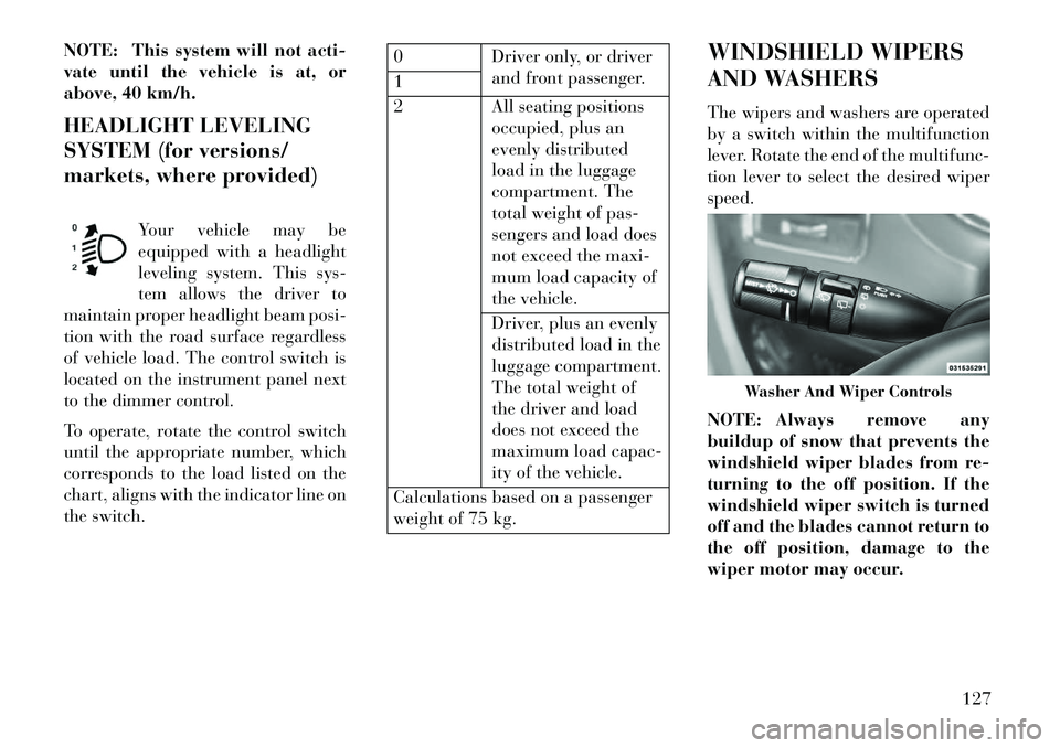
The wipers and washers are operated
by a switch within the multifunction
lever. Rotate the end of the multifunc-
tion lever to select the desired wiper
speed.
NOTE: Always remove any
buildup of snow that prevents the
windshield wiper blades from re-
turning to the off position. If the
windshield wiper switch is turned
off and the blades cannot return to
the off position, damage to the
wiper motor may occur.
Washer And Wiper Controls
127
Page 161 of 360
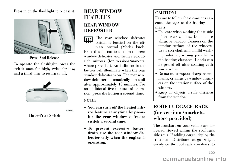
Press in on the flashlight to release it.
To operate the flashlight, press the
switch once for high, twice for low,
and a third time to return to off.REAR WINDOW
FEATURES
REAR WINDOW
DEFROSTER
The rear window defroster
button is located on the cli-
mate control (Mode) knob.
Press this button to turn on the rear
window defroster and the heated out-
side mirrors (for versions/markets,
where provided). An indicator in the
button will illuminate when the rear
window defroster is on. The rear win-
dow defroster automatically turns off
after approximately 10 minutes. For
an additional five minutes of opera-
tion, press the button a second time.
NOTE:
You can turn off the heated mir- ror feature at anytime by press-
ing the rear window defroster
switch a second time.
To prevent excessive battery drain, use the rear window de-
froster only when the engine is
operating.
CAUTION!
Failure to follow these cautions can
cause damage to the heating ele-
ments:
Use care when washing the insideof the rear window. Do not use
abrasive window cleaners on the
interior surface of the window.
Use a soft cloth and a mild wash-
ing solution, wiping parallel to
the heating elements. Labels can
be peeled off after soaking with
warm water.
Do not use scrapers, sharp instru- ments, or abrasive window clean-
ers on the interior surface of the
window.
Keep all objects a safe distance
from the window.
ROOF LUGGAGE RACK
(for versions/markets,
where provided)
The crossbars on your vehicle are de-
livered stowed within the roof rack
side rails. If adding cargo, deploy the
crossbars. Distribute cargo weight
evenly on the roof rack crossbars, to
Press And ReleaseThree-Press Switch
155
Page 162 of 360
maximum of 68 kg. The roof rack
does not increase the total load carry-
ing capacity of the vehicle. Be sure the
total load of cargo inside the vehicle
plus that on the external rack does not
exceed the maximum vehicle load ca-
pacity.
The crossbars and side rails are de-
signed to carry weight on vehicles
equipped with a luggage rack. The
load must not exceed 68 kg, and
should be uniformly distributed over
the luggage rack crossbars.
NOTE:
Crossbars are error-proofed andcannot be deployed or stowed in
the incorrect positions. To help control wind noise, stow
the crossbars in the side rails
when they are not in use.
DEPLOYING THE
CROSSBARS
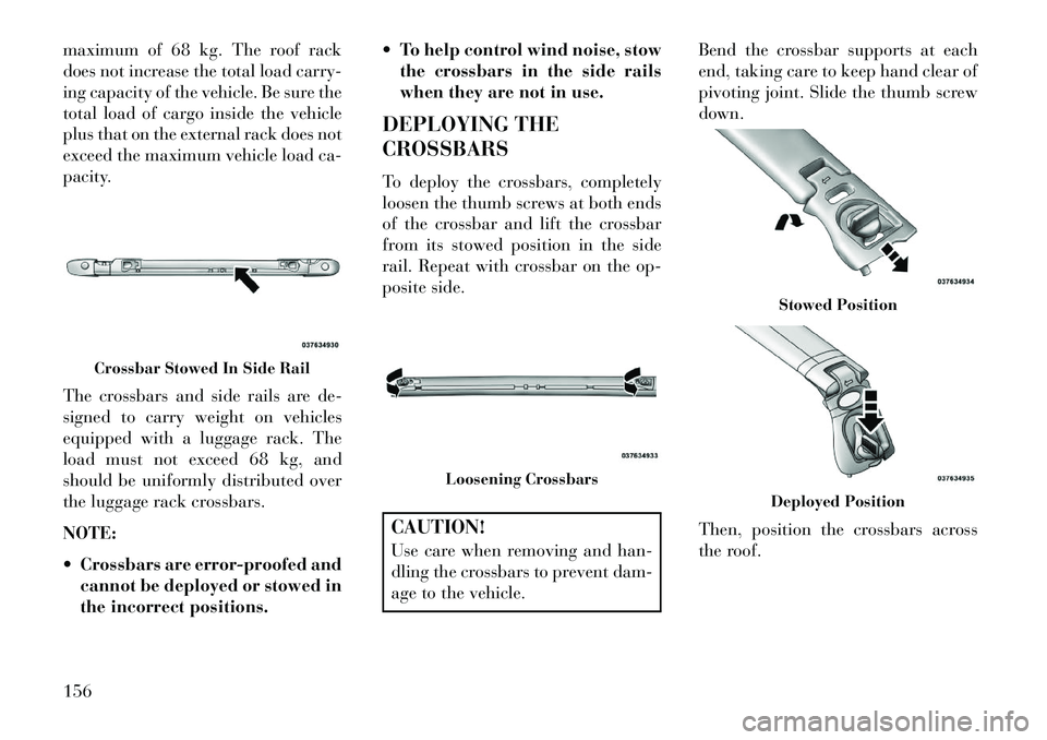
To deploy the crossbars, completely
loosen the thumb screws at both ends
of the crossbar and lift the crossbar
from its stowed position in the side
rail. Repeat with crossbar on the op-
posite side.
CAUTION!
Use care when removing and han-
dling the crossbars to prevent dam-
age to the vehicle. Bend the crossbar supports at each
end, taking care to keep hand clear of
pivoting joint. Slide the thumb screw
down.
Then, position the crossbars across
the roof.
Crossbar Stowed In Side Rail
Loosening Crossbars
Stowed PositionDeployed Position
156
Page 190 of 360

may occur with severe usage, such as
trailer towing. If this light turns on,
safely pull over and stop the vehicle.
Then, shift the transmission into
NEUTRAL and run the engine at idle
or faster until the light turns off.CAUTION!
Continuous driving with the Trans-
mission Temperature Warning
Light illuminated will eventually
cause severe transmission damage
or transmission failure.WARNING!
If the Transmission Temperature
Warning Light is illuminated and
you continue operating the vehicle,
in some circumstances you could
cause the fluid to boil over, come in
contact with hot engine or exhaust
components and cause a fire.
OIL CHANGE DUE
Your vehicle is equipped with an en-
gine oil change indicator system. The
“Oil Change Due” message will flash in the EVIC display for approxi-
mately 10 seconds after a single chime
has sounded to indicate the next
scheduled oil change interval. The en-
gine oil change indicator system is
duty cycle based, which means the
engine oil change interval may fluctu-
ate dependent upon your personal
driving style.
Unless reset, this message will continue
to display each time you cycle the igni-
tion to the ON/RUN position. To turn
off the message temporarily, press and
release the BACK button. To reset the
oil change indicator system please refer
to a Lancia Dealership.FUEL ECONOMY
Press and release the UP or DOWN
button until “Fuel Economy” displays
highlighted in the EVIC and press the
SELECT button. The following Fuel
Economy functions display in the
EVIC:
Average Fuel Economy (AVG)
Distance To Empty (DTE)
Liters Per 100km (L/100km)Average Fuel Economy
Shows the average fuel economy since
the last reset. The Average Fuel
Economy can be reset by following
the prompt in the EVIC to use the
SELECT button. When the fuel
economy is reset, the display will read
“zero” for two seconds. Then, the his-
tory information will be erased, and
the averaging will continue from the
last fuel average reading before the
reset.
Distance To Empty (DTE)
Shows the estimated distance that can
be traveled with the fuel remaining in
the tank. This estimated distance is
determined by a weighted average of
the instantaneous and average fuel
economy, according to the current
Average Fuel Economy Display
184
Page 264 of 360
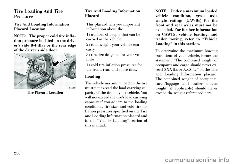
Tire Loading And Tire
Pressure
Tire And Loading Information
Placard Location
NOTE: The proper cold tire infla-
tion pressure is listed on the driv-
er’s side B-Pillar or the rear edge
of the driver's side door.Tire And Loading Information
Placard
This placard tells you important
information about the:
1) number of people that can be
carried in the vehicle
2) total weight your vehicle can
carry
3) tire size designed for your ve-
hicle
4) cold tire inflation pressures for
the front, rear, and spare tires.
Loading
The vehicle maximum load on the tire
must not exceed the load carrying ca-
pacity of the tire on your vehicle. You
will not exceed the tire's load carrying
capacity if you adhere to the loading
conditions, tire size, and cold tire in-
flation pressures specified on the Tire
and Loading Information placard and
in the “Vehicle Loading” section of
this manual. NOTE: Under a maximum loaded
vehicle condition, gross axle
weight ratings (GAWRs) for the
front and rear axles must not be
exceeded. For further information
on GAWRs, vehicle loading, and
trailer towing, refer to “Vehicle
Loading” in this section.
To determine the maximum loading
conditions of your vehicle, locate the
statement “The combined weight of
occupants and cargo should never ex-
ceed XXX lbs or XXX kg” on the Tire
and Loading Information placard.
The combined weight of occupants,
cargo/luggage and trailer tongue
weight (if applicable) should never
exceed the weight referenced here.
Tire Placard Location
258
Page 265 of 360

Steps For Determining Correct
Load Limit
1. Locate the statement “The com-
bined weight of occupants and cargo
should never exceed XXX lbs or
XXX kg” on your vehicle's placard.
2. Determine the combined weight of
the driver and passengers that will be
riding in your vehicle.
3. Subtract the combined weight of
the driver and passengers from
XXX lbs or XXX kg.4. The resulting figure equals the
available amount of cargo and lug-
gage load capacity. For example, if
“XXX” amount equals 1,400 lbs
(635 kg) and there will be five 150 lb
(68 kg) passengers in your vehicle,
the amount of available cargo and
luggage load capacity is 650 lbs
(295 kg) (since 5 x 150 = 750, and
1400 – 750 = 650 lbs [295 kg]).
5. Determine the combined weight of
luggage and cargo being loaded on the
vehicle. That weight may not safely
exceed the available cargo and lug-
gage load capacity calculated in Step
4.
6. If your vehicle will be towing a
trailer, load from your trailer will be
transferred to your vehicle. Consult
this manual to determine how this
reduces the available cargo and lug-
gage load capacity of your vehicle.NOTE:
The following table shows ex-
amples on how to calculate total
load, cargo/luggage, and towing
capacities of your vehicle with
varying seating configurations
and number and size of occu-
pants. This table is for illustra-
tion purposes only and may not
be accurate for the seating and
load carry capacity of your ve-
hicle.
For the following example, the combined weight of occupants
and cargo should never exceed
865 lbs (392 kg).
259