steering Lancia Voyager 2014 Owner handbook (in English)
[x] Cancel search | Manufacturer: LANCIA, Model Year: 2014, Model line: Voyager, Model: Lancia Voyager 2014Pages: 364, PDF Size: 3.49 MB
Page 84 of 364
RAIN SENSING WIPERS (for versions/markets,where provided) ....................... .134
TILT/TELESCOPING STEERING COLUMN .....135
ADJUSTABLE PEDALS (for versions/markets, where provided) .............................. .135
ELECTRONIC SPEED CONTROL ............136
TO ACTIVATE ......................... .137
TO SET A DESIRED SPEED ...............137
TO DEACTIVATE ...................... .137
TO RESUME SPEED .................... .137
TO VARY THE SPEED SETTING ...........137
TO ACCELERATE FOR PASSING ...........138
PARKSENSE® REAR PARK ASSIST (for versions/markets, where provided) ...........138
PARK ASSIST SENSORS .................138
PARKSENSE® WARNING DISPLAY .........138
PARKSENSE® DISPLAY .................139
ENABLING/DISABLING PARKSENSE® ......140
SERVICE THE PARKSENSE® REAR PARK ASSIST SYSTEM ...................... .140
CLEANING THE PARK ASSIST SYSTEM .....141
PARKSENSE® SYSTEM USAGE PRECAUTIONS ........................ .141
PARKVIEW® REAR BACK UP CAMERA (for versions/markets, where provided) ...........143
TURNING PARKVIEW® ON OR OFF — WITH NAVIGATION/MULTIMEDIA RADIO .........144
78
Page 95 of 364
Blind Spot Alert Off
When the BSM system is turned off
there will be no visual or audible
alerts from either the BSM or RCP
systems.
NOTE: The BSM system will store
the current operating mode when
the vehicle is shut off. Each time
the vehicle is started the previ-
ously stored mode will be recalled
and used
Uconnect® PHONE
NOTE: For Uconnect® Phone
with Navigation or Multimedia ra-
dio, refer to the Navigation or Mul-
timedia radio's User's Manual
(separate booklet) Uconnect®
Phone section.
Uconnect® Phone is a voice-
activated, hands-free, in-vehicle com-
munications system. Uconnect®
Phone allows you to dial a phone
number with your mobile phone* us-
ing simple voice commands (e.g.,
“Call”…“Jim”… “Work” or
“Dial”…“151-1234 -5555”). Your
mobile phone's audio is transmittedthrough your vehicle's audio system;
the system will automatically mute
your radio when using the Uconnect®
Phone.
Uconnect® Phone allows you to
transfer calls between the Uconnect®
Phone and your mobile phone as you
enter or exit your vehicle and enables
you to mute the Uconnect® Phone's
microphone for private conversation.
The Uconnect® Phone is driven
through your Bluetooth® “Hands-
Free profile” mobile phone.
Uconnect® Phone features
Bluetooth® technology - the global
standard that enables different elec-
tronic devices to connect to each other
without wires or a docking station, so
Uconnect® Phone works no matter
where you stow your mobile phone
(be it your purse, pocket, or brief-
case), as long as your phone is turned
on and has been paired to the vehicle's
Uconnect® Phone. The Uconnect®
Phone allows up to seven mobile
phones to be linked to the system.
Only one linked (or paired) mobile
phone can be used with the
Uconnect® Phone at a time. The
Uconnect® Phone is available in Eng-
lish, Dutch, French, German, Italian
or Spanish languages (as equipped).
WARNING!
Any voice commanded system
should be used only in safe driving
conditions following all applicable
laws, including laws regarding
phone use. Your attention should be
focused on safely operating the ve-
hicle. Failure to do so may result in
a collision causing serious injury or
death.
Uconnect® Phone Button The radio or steering wheel
controls will contain the
two control buttons
(Uconnect® Phone
but-
ton and Voice Command
button)
that will enable you to access the sys-
tem. When you press the button you
will hear the word Uconnect® fol-
lowed by a BEEP. The beep is your
signal to give a command.
89
Page 96 of 364
Voice Command Button
Actual button location may
vary with radio. The indi-
vidual buttons are described
in the “Operation” section.
The Uconnect® Phone can be used
with Hands-Free Profile certified
Bluetooth® mobile phones. Some
phones may not support all the
Uconnect® Phone features. Refer to
your mobile service provider or the
phone manufacturer for details.
The Uconnect® Phone is fully inte-
grated with the vehicle's audio sys-
tem. The volume of the Uconnect®
Phone can be adjusted either from the
radio volume control knob or from the
steering wheel radio control, if so
equipped.
The radio display will be used for
visual prompts from the Uconnect®
Phone such as CELL or caller ID on
certain radios.
COMPATIBLE PHONES
* The Uconnect® Phone requires a
mobile phone equipped with the
Bluetooth® “Hands-Free Profile”,
version 1.0 or higher.
See Uconnect® website for supported
phones.
www.UconnectPhone.com
To find the list of compatible phones
navigate through the following
menus:
Select model year for the vehicle
Select type of the vehicle
In the getting started tab, selectcompatible phones
OPERATION
Voice commands can be used to oper-
ate the Uconnect® Phone and to navi-
gate through the Uconnect® Phone
menu structure. Voice commands are
required after most Uconnect® Phone
prompts. You will be prompted for a
specific command and then guided
through the available options. Prior to giving a voice command,
one must wait for the beep, which
follows the “Ready” prompt or an-
other prompt.
For certain operations, compound commands can be used. For ex-
ample, instead of saying “Setup”
and then “Phone Pairing”, the fol-
lowing compound command can be
said: “Setup Phone Pairing”.
For each feature explanation in this section, only the compound form of
the voice command is given. You
can also break the commands into
parts and say each part of the com-
mand when you are asked for it.
For example, you can use the com-
pound form voice command
“Phonebook New Entry”, or you
can break the compound form
command into two voice com-
mands: “Phonebook” and “New
Entry”. Please remember, the
Uconnect® Phone works best when
you talk in a normal conversational
tone, as if speaking to someone sit-
ting a few meters away from you.
90
Page 134 of 364
you. For details, refer to “Elec-
tronic Vehicle Information Center
(EVIC)/Customer-Programmable
Features” in “Understanding Your
Instrument Panel” for further in-
formation.
TO OPEN AND CLOSE
THE HOOD
To open the hood, two latches must be
released.
1. Pull the hood release lever located
on the instrument panel, below the
steering column.
2. Move to the front of the vehicle
and look inside the center of the hood
opening. Locate, then push the safety
catch lever downward while raising
the hood at the same time.Use the hood prop rod to secure the
hood in the open position.
CAUTION!
To prevent possible damage, do not
slam the hood to close it. Lower the
hood until it is open approximately
30 cm and then drop it. This should
secure both latches. Never drive
your vehicle unless the hood is fully
closed, with both latches engaged.
WARNING!
Be sure the hood is fully latched
before driving your vehicle. If the
hood is not fully latched, it could
open when the vehicle is in motion
and block your vision. Failure to
follow this warning could result in
serious injury or death.
LIGHTS
All of the lights, except the Hazard
Warning lights, headlight high beams
and flash-to-pass, are controlled by
switches to the left of the steering
column on the instrument panel.
Hood Release Lever
Safety Lever Location
Headlight Switch With Halo Control
Assembly
128
Page 137 of 364
come on. Press the switch a second
time and the rear fog lights will come
on (front fog lights stay on). Press the
switch a third time and the rear fog
lights turn off (front fog stays on).
Press the switch a fourth times and
the front fog turns off. For vehicles
without front fog, rear fog will acti-
vate on the first press.
An indicator light in the instrument
cluster illuminates when the fog lights
are turned on.
NOTE: The headlight switch must
be in parking lights or headlights
position to activate the front and
rear fog lamps.
BATTERY PROTECTION
This feature provides battery protec-
tion to avoid wearing down the bat-
tery if the headlights, parking lights,
or front fog lights are left on for ex-
tended periods of time when the igni-
tion switch is in the LOCK position.
After eight minutes of the ignition
switch being in the LOCK position
and the headlight switch in any posi-
tion other than OFF or AUTO, thelights will turn off automatically until
the next cycle of the ignition switch or
headlight switch.
The battery protection feature will be
disabled if the ignition switch is
turned to any other position other
than LOCK during the eight minute
delay.
MULTIFUNCTION LEVER
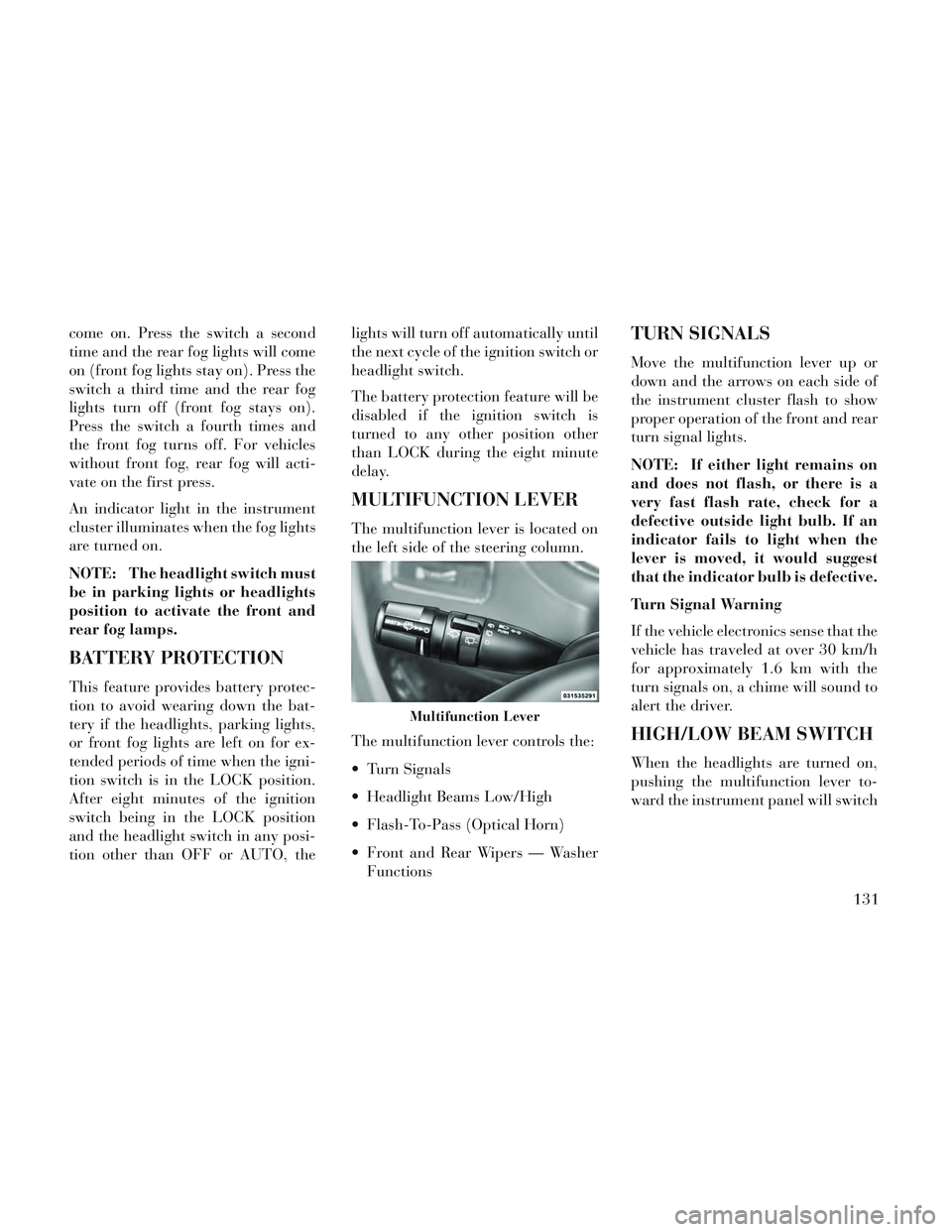
The multifunction lever is located on
the left side of the steering column.
The multifunction lever controls the:
Turn Signals
Headlight Beams Low/High
Flash-To-Pass (Optical Horn)
Front and Rear Wipers — Washer
Functions
TURN SIGNALS
Move the multifunction lever up or
down and the arrows on each side of
the instrument cluster flash to show
proper operation of the front and rear
turn signal lights.
NOTE: If either light remains on
and does not flash, or there is a
very fast flash rate, check for a
defective outside light bulb. If an
indicator fails to light when the
lever is moved, it would suggest
that the indicator bulb is defective.
Turn Signal Warning
If the vehicle electronics sense that the
vehicle has traveled at over 30 km/h
for approximately 1.6 km with the
turn signals on, a chime will sound to
alert the driver.
HIGH/LOW BEAM SWITCH
When the headlights are turned on,
pushing the multifunction lever to-
ward the instrument panel will switch
Multifunction Lever
131
Page 139 of 364

2All seating positions occupied,
plus an evenly distributed
load in the luggage compart-
ment. The total weight of pas-
sengers and load does not ex-
ceed the maximum load
capacity of the vehicle.
Calculations based on a passenger weight of 75 kg.
WINDSHIELD WIPERS
AND WASHERS
The wipers and washers are operated
by a switch within the multifunction
lever. Rotate the end of the multifunc-
tion lever to select the desired wiper
speed. NOTE: Always remove any
buildup of snow that prevents the
windshield wiper blades from re-
turning to the off position. If the
windshield wiper switch is turned
off and the blades cannot return to
the off position, damage to the
wiper motor may occur.
WARNING!
Sudden loss of visibility through
the windshield could lead to a col-
lision. You might not see other ve-
hicles or other obstacles. To avoid
sudden icing of the windshield dur-
ing freezing weather, warm the
windshield with the defroster be-
fore and during windshield washer
use.
MIST, FRONT WIPER AND
WASHER
Use the Mist feature when weather
conditions make occasional usage of
the wipers necessary.
Press the end of the multifunction lever
inward (toward the steering column) to
the first detent and release for a single wiping cycle. To use the Washer, push
on the end of the lever to the second
detent and hold while spray is desired.
If the lever is pushed while on the in-
termittent setting, the wipers will turn
on and operate for several wipe cycles
after the lever is released, and then
resume the intermittent interval previ-
ously selected. If the lever is pushed
while the wipers are in the off position,
the wipers will operate several wipe
cycles, then turn off.
INTERMITTENT, LOW AND
HIGH SPEED WIPERS
Rotate the end of the lever to one of
the first five detent positions for inter-
mittent wiper operation, the sixth de-
tent for low wiper operation and the
seventh detent for high wiper opera-
tion.
Use one of the five intermittent wiper
settings when weather conditions
make a single wiping cycle, with a
variable delay between cycles, desir-
able. At driving speeds above
16 km/h, the delay can be regulated
from a maximum of approximately
Washer And Wiper Controls
133
Page 141 of 364
(Customer-Programmable Fea-
tures)” in “Understanding Your
Instrument Panel” for further
information.
The Rain Sensing system has protec-
tive features for the wiper blades and
arms. It will not operate under the
following conditions:
Low Temperature Wipe Inhibit
— The Rain Sensing feature will
not operate when the ignition is
first switched ON, and the vehicle is
stationary, and the outside tem-
perature is below 0°C, unless the
wiper control on the multifunction
lever is moved, or the vehicle speed
becomes greater than 0 km/h, or
the outside temperature rises above
freezing.
Neutral Wipe Inhibit — The Rain
Sensing feature will not operate
when the ignition is ON, and the
transmission shift lever is in the
NEUTRAL position, and the ve-
hicle speed is less than 8 km/h, unless the wiper control on the mul-
tifunction lever is moved or the
shift lever is moved out of the NEU-
TRAL position.
TILT/TELESCOPING
STEERING COLUMN
This feature allows you to tilt the
steering column upward or down-
ward. It also allows you to lengthen or
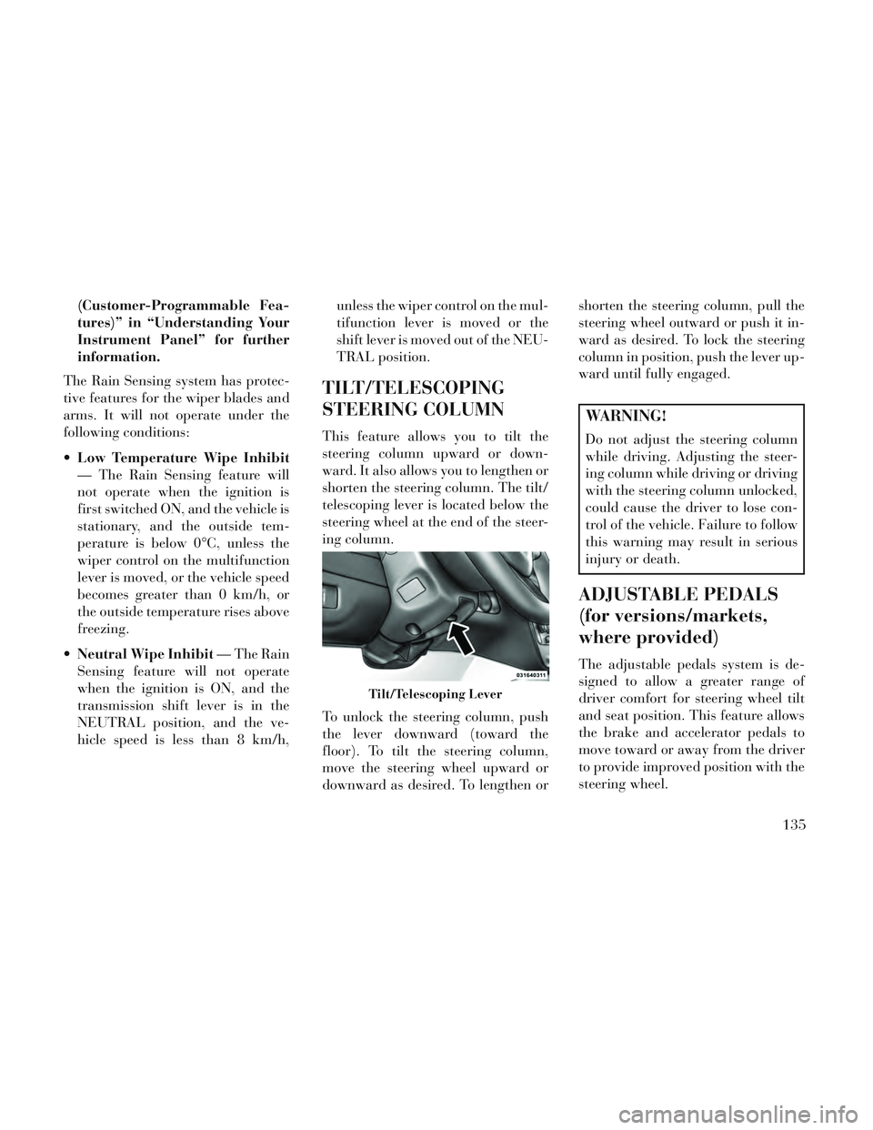
shorten the steering column. The tilt/
telescoping lever is located below the
steering wheel at the end of the steer-
ing column.
To unlock the steering column, push
the lever downward (toward the
floor). To tilt the steering column,
move the steering wheel upward or
downward as desired. To lengthen orshorten the steering column, pull the
steering wheel outward or push it in-
ward as desired. To lock the steering
column in position, push the lever up-
ward until fully engaged.
WARNING!
Do not adjust the steering column
while driving. Adjusting the steer-
ing column while driving or driving
with the steering column unlocked,
could cause the driver to lose con-
trol of the vehicle. Failure to follow
this warning may result in serious
injury or death.
ADJUSTABLE PEDALS
(for versions/markets,
where provided)
The adjustable pedals system is de-
signed to allow a greater range of
driver comfort for steering wheel tilt
and seat position. This feature allows
the brake and accelerator pedals to
move toward or away from the driver
to provide improved position with the
steering wheel.
Tilt/Telescoping Lever
135
Page 142 of 364
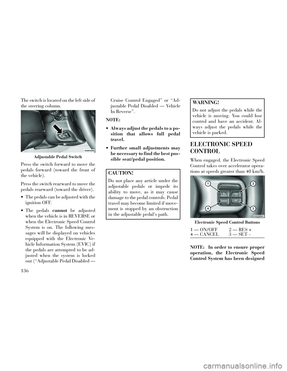
The switch is located on the left side of
the steering column.
Press the switch forward to move the
pedals forward (toward the front of
the vehicle).
Press the switch rearward to move the
pedals rearward (toward the driver).
The pedals can be adjusted with theignition OFF.
The pedals cannotbe adjusted
when the vehicle is in REVERSE or
when the Electronic Speed Control
System is on. The following mes-
sages will be displayed on vehicles
equipped with the Electronic Ve-
hicle Information System (EVIC) if
the pedals are attempted to be ad-
justed when the system is locked
out (“Adjustable Pedal Disabled — Cruise Control Engaged” or “Ad-
justable Pedal Disabled — Vehicle
In Reverse”.
NOTE:
Always adjust the pedals to a po- sition that allows full pedal
travel.
Further small adjustments may be necessary to find the best pos-
sible seat/pedal position.
CAUTION!
Do not place any article under the
adjustable pedals or impede its
ability to move, as it may cause
damage to the pedal controls. Pedal
travel may become limited if move-
ment is stopped by an obstruction
in the adjustable pedal's path.
WARNING!
Do not adjust the pedals while the
vehicle is moving. You could lose
control and have an accident. Al-
ways adjust the pedals while the
vehicle is parked.
ELECTRONIC SPEED
CONTROL
When engaged, the Electronic Speed
Control takes over accelerator opera-
tions at speeds greater than 40 km/h.
NOTE: In order to ensure proper
operation, the Electronic Speed
Control System has been designedAdjustable Pedal Switch
Electronic Speed Control Buttons
1 — ON/OFF 2 — RES +
4 — CANCEL 3 — SET -
136
Page 169 of 364

CAUTION!
Check deployed crossbars fre-quently and retighten thumb
screws as necessary.
To avoid damage to the roof rack and vehicle, do not exceed the
maximum roof rack load capacity
of 68 kg. Always distribute heavy
loads as evenly as possible and
secure the load appropriately.
To prevent damage to the roof of your vehicle, DO NOT carry any
loads on the roof rack without the
crossbars deployed.
(Continued)
CAUTION!(Continued)
The load should be secured andplaced on top of the crossbars, not
directly on the roof. If it is neces-
sary to place the load on the roof,
place a blanket or other protec-
tive layer between the load and
the roof surface.
Long loads which extend over the windshield, such as wood panels
or surfboards, or loads with large
frontal area should be secured to
both the front and rear of the
vehicle.
Travel at reduced speeds and turn corners carefully when carrying
large or heavy loads on the roof
rack. Wind forces, due to natural
causes or nearby truck traffic,
can add sudden upward lift to a
load. This is especially true on
large flat loads and may result in
damage to the cargo or your ve-
hicle.
WARNING!
Cargo must be securely tied before
driving your vehicle. Improperly
secured loads can fly off the vehicle,
particularly at high speeds, result-
ing in personal injury or property
damage. Follow the roof rack cau-
tions when carrying cargo on your
roof rack.
HEADLIGHT WASHER
(for versions/markets,
where provided)
The multifunction lever operates the
headlight washers when the ignition
switch is in the ON position and the
headlights are turned on. The multi-
function lever is located on the left
side of the steering column.
To use the headlight washers, push
the multifunction lever inward (to-
ward the steering column) to the sec-
ond detent and release it. The head-
light washers will spray a timed high-
pressure spray of washer fluid onto
each headlight lens. In addition, the
Rail Tie Loops
163
Page 174 of 364

INFORMATION MODE DISPLAY...........209
NUMERIC KEYPAD MENU ................209
DISC MENU .......................... .209
DISPLAY SETTINGS ................... .209
LISTENING TO AUDIO WITH THE SCREEN CLOSED ............................. .210
DISC FORMATS ....................... .210
DISPLAY ............................ .213
PRODUCT AGREEMENT .................215
STEERING WHEEL AUDIO CONTROLS .......217
RADIO OPERATION .................... .218
CDPLAYER...........................218
CD/DVD DISC MAINTENANCE ..............218
RADIO OPERATION AND MOBILE PHONES . . . .218
CLIMATE CONTROLS .................... .219
AUTOMATIC TEMPERATURE CONTROL (ATC) ............................... .219
SUMMER OPERATION ...................224
WINTER OPERATION ...................225
VACATION/STORAGE ...................225
WINDOW FOGGING ................... .225
OUTSIDE AIR INTAKE ...................225
A/CAIRFILTER .......................225
OPERATING TIPS ..................... .225
168