stop start Lancia Voyager 2014 Owner handbook (in English)
[x] Cancel search | Manufacturer: LANCIA, Model Year: 2014, Model line: Voyager, Model: Lancia Voyager 2014Pages: 364, PDF Size: 3.49 MB
Page 238 of 364
ignition switch to the LOCK position,
wait 10 to 15 seconds, then repeat the
“Normal Starting” procedure.
KEYLESS ENTER-N-GO™
(for versions/markets,
where provided)
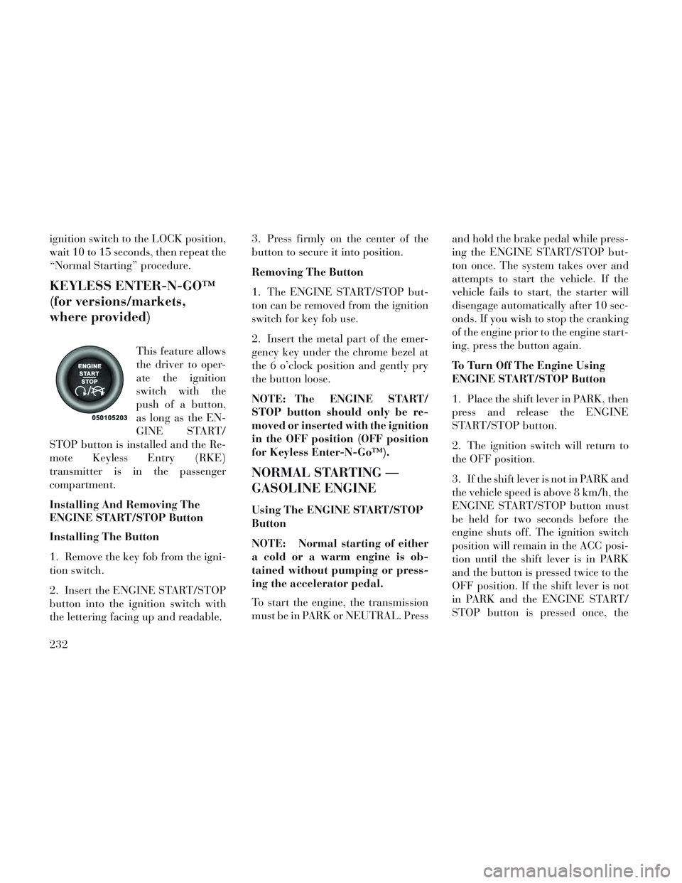
This feature allows
the driver to oper-
ate the ignition
switch with the
push of a button,
as long as the EN-
GINE START/
STOP button is installed and the Re-
mote Keyless Entry (RKE)
transmitter is in the passenger
compartment.
Installing And Removing The
ENGINE START/STOP Button
Installing The Button
1. Remove the key fob from the igni-
tion switch.
2. Insert the ENGINE START/STOP
button into the ignition switch with
the lettering facing up and readable. 3. Press firmly on the center of the
button to secure it into position.
Removing The Button
1. The ENGINE START/STOP but-
ton can be removed from the ignition
switch for key fob use.
2. Insert the metal part of the emer-
gency key under the chrome bezel at
the 6 o’clock position and gently pry
the button loose.
NOTE: The ENGINE START/
STOP button should only be re-
moved or inserted with the ignition
in the OFF position (OFF position
for Keyless Enter-N-Go™).
NORMAL STARTING —
GASOLINE ENGINE
Using The ENGINE START/STOP
Button
NOTE: Normal starting of either
a cold or a warm engine is ob-
tained without pumping or press-
ing the accelerator pedal.
To start the engine, the transmission
must be in PARK or NEUTRAL. Press
and hold the brake pedal while press-
ing the ENGINE START/STOP but-
ton once. The system takes over and
attempts to start the vehicle. If the
vehicle fails to start, the starter will
disengage automatically after 10 sec-
onds. If you wish to stop the cranking
of the engine prior to the engine start-
ing, press the button again.
To Turn Off The Engine Using
ENGINE START/STOP Button
1. Place the shift lever in PARK, then
press and release the ENGINE
START/STOP button.
2. The ignition switch will return to
the OFF position.
3. If the shift lever is not in PARK and
the vehicle speed is above 8 km/h, the
ENGINE START/STOP button must
be held for two seconds before the
engine shuts off. The ignition switch
position will remain in the ACC posi-
tion until the shift lever is in PARK
and the button is pressed twice to the
OFF position. If the shift lever is not
in PARK and the ENGINE START/
STOP button is pressed once, the
232
Page 239 of 364
EVIC will display a “Vehicle Not In
Park” message and the engine will
remain running. Never leave a vehicle
out of the PARK position, or it could
roll.
NOTE: If the ignition switch is left
in the ACC or RUN (engine not run-
ning) position and the transmis-
sion is in PARK, the system will
automatically time out after 30
minutes of inactivity and the igni-
tion will switch to the OFF posi-
tion.
Keyless Enter-N-Go™ Functions –
With Driver’s Foot OFF The
Brake Pedal (In PARK Or
NEUTRAL Position)
The Keyless Enter-N-Go™ feature
operates similar to an ignition switch.
It has four positions, OFF, ACC, RUN
and START. To change the ignition
switch positions without starting the
vehicle and use the accessories follow
these steps. Starting with the ignition switch in
the OFF position:
Press the ENGINE START/STOP button once to change the ignition
switch to the ACC position (EVIC
displays “IGNITION MODE
ACCESSORY”),
Press the ENGINE START/STOP button a second time to change the
ignition switch to the RUN position
(EVIC displays “IGNITION MODE
RUN”),
Press the ENGINE START/STOP button a third time to return the
ignition switch to the OFF position
(EVIC displays “IGNITION MODE
OFF”).
EXTREME COLD
WEATHER (BELOW �29°C)
To ensure reliable starting at these
temperatures, use of an externally
powered electric engine block heater
is recommended.
IF ENGINE FAILS TO
START
WARNING!
Never pour fuel or other flam-mable liquids into the throttle
body air inlet opening in an at-
tempt to start the vehicle. This
could result in a flash fire causing
serious personal injury.
Do not attempt to push or tow your vehicle to get it started. Ve-
hicles equipped with an auto-
matic transmission cannot be
started this way. Unburned fuel
could enter the catalytic con-
verter and once the engine has
started, ignite and damage the
converter and vehicle.
(Continued)
233
Page 240 of 364
WARNING!(Continued)
If the vehicle has a dischargedbattery, booster cables may be
used to obtain a start from a
booster battery or the battery in
another vehicle. This type of start
can be dangerous if done improp-
erly. Refer to “Jump Starting” in
“What To Do In Emergencies” for
further information.
Clearing A Flooded Engine (Using
ENGINE START/STOP Button)
If the engine fails to start after you
have followed the “Normal Starting”
or “Extreme Cold Weather" proce-
dures, it may be flooded. To clear any
excess fuel:
1. Press and hold the brake pedal.
2. Press the accelerator pedal all the
way to the floor and hold it.
3. Press and release the ENGINE
START/STOP button once.
The starter motor will engage auto-
matically, run for 10 seconds, and then
disengage. Once this occurs, release the accelerator pedal and the brake pedal,
wait 10 to 15 seconds, then repeat the
“Normal Starting” procedure.
Clearing A Flooded Engine (Using
Fob With Integrated Key)
If the engine fails to start after you
have followed the “Normal Starting”
or “Extreme Cold Weather” proce-
dures, it may be flooded. To clear any
excess fuel:
1. Press the accelerator pedal all the
way to the floor and hold it.
2. place the ignition in the START
position and release it as soon as the
starter engages.
The starter motor will disengage auto-
matically in 10 seconds. Once this oc-
curs, release the accelerator pedal, turn
the ignition switch to the LOCK posi-
tion, wait 10 to 15 seconds, then repeat
the “Normal Starting” procedure.
CAUTION!
To prevent damage to the starter,
wait 10 to 15 seconds before trying
again.
AFTER STARTING
The idle speed is controlled automati-
cally and it will decrease as the engine
warms up.
NORMAL STARTING –
DIESEL ENGINE
1. Turn the ignition switch to the ON
position.
2. Watch for the “Wait To Start
Light” in the instrument cluster. Refer
to “Instrument Cluster” in “Under-
standing Your Instrument Panel” for
further information. It will illuminate
for two to ten seconds or more, de-
pending on engine temperature.
When the “Wait To Start Light” goes
out, the engine is ready to start.
3. DO NOT press the accelerator.
Turn the ignition switch to the START
position and release when the engine
starts.
234
Page 241 of 364

CAUTION!
To prevent damage to the starter,
DO NOT crank the engine for more
than 15 second intervals at one
time. Wait 10 to 15 seconds before
trying again.
4. After the engine starts, allow it to
idle for approximately 30 seconds be-
fore driving. This allows oil to circu-
late and lubricate the turbocharger. Starting And Operating Cautions
– Diesel Engine
WARNING!
NEVER pour fuel or other flam-
mable liquid into the air inlet open-
ing in an attempt to start the ve-
hicle. This could result in a flash
fire causing serious personal injury.
Running a cold engine at high speeds during driving or idling may
damage engine components.
Before turning off your turbo diesel engine, always allow the engine to
return to normal idle speed and run
for several seconds. This assures proper lubrication of the turbo-
charger. This is particularly neces-
sary after any period of hard driv-
ing.
Turbocharger Cool Down
NOTE: Letting the engine idle af-
ter extended operation allows the
turbine housing to cool to normal
operating temperature.
The following chart should be used as
a guide in determining the amount of
engine idle time required to suffi-
ciently cool down the turbocharger
before shut down, depending upon
the type of driving and the amount of
cargo.
Turbocharger "Cool Down" Chart
Driving
Conditions
Load Turbocharger
Temperature
Idle Time (in minutes)
Before Shut Down
Stop & Go EmptyCoolLess than 1
Stop & Go MediumWarm 1
Highway Speeds MediumWarm 2
City Traffic Max. GCWR Warm3
Highway Speeds Max. GCWR Warm4
Uphill Grade Max. GCWR Hot5
235
Page 243 of 364

KEY IGNITION PARK
INTERLOCK
This vehicle is equipped with a Key
Ignition Park Interlock which re-
quires the transmission to be in PARK
before the ignition switch can be
turned to the LOCK position. The key
fob can only be removed from the
ignition when the ignition is in the
LOCK position, and the transmission
is locked in PARK whenever the igni-
tion switch is in the LOCK position.
NOTE: If a malfunction occurs,
the system will trap the key fob in
the ignition switch to warn you
that this safety feature is inoper-
able. The engine can be started
and stopped but the key fob cannot
be removed until you obtain ser-
vice.
BRAKE/TRANSMISSION
SHIFT INTERLOCK
SYSTEM
This vehicle is equipped with a Brake
Transmission Shift Interlock System
(BTSI) that holds the shift lever in
PARK unless the brakes are applied.To shift the transmission out of PARK,
the ignition switch must be turned to
the ON/RUN position (engine run-
ning or not) and the brake pedal must
be pressed.
SIX-SPEED AUTOMATIC
TRANSMISSION
The transmission gear position dis-
play (located in the instrument clus-
ter) indicates the transmission gear
range. You must press the brake pedal
to move the shift lever out of PARK
(Refer to Brake/Transmission Shift
Interlock System in this section). To
drive, move the shift lever from PARK
or NEUTRAL to the DRIVE position.
The electronically-controlled trans-
mission provides a precise shift sched-
ule. The transmission electronics are
self-calibrating; therefore, the first
few shifts on a new vehicle may be
somewhat abrupt. This is a normal
condition, and precision shifts will de-
velop within a few hundred kilome-
ters.
Only shift from DRIVE to PARK or
REVERSE when the accelerator
pedal is released and the vehicle is
stopped. Be sure to keep your foot on
the brake pedal when shifting be-
tween these gears.
The transmission shift lever has only
PARK, REVERSE, NEUTRAL, and
DRIVE shift positions. Manual down-
shifts can be made using the Elec-
tronic Range Select (ERS) shift con-
trol (described later in this section).
Moving the shift lever to the left or
right (–/ +) while in the DRIVE posi-
tion will select the highest available
transmission gear, and will display
that gear in the instrument cluster as
6, 5, 4, 3, 2, 1.Shift Lever
237
Page 245 of 364
WARNING!(Continued)
When leaving the vehicle, alwaysremove the key fob and lock your
vehicle.
Never leave children alone in a vehicle, or with access to an un-
locked vehicle.
Allowing children to be in a ve- hicle unattended is dangerous for
a number of reasons. A child or
others could be seriously or fa-
tally injured. Children should be
warned not to touch the parking
brake, brake pedal or the shift
lever.
Do not leave the key fob in or near the vehicle, (or in a location ac-
cessible to children), and do not
leave the ignition (in a vehicle
equipped with Keyless Enter-N-
Go™) in the ACC or ON/RUN
position A child could operate
power windows, other controls, or
move the vehicle.
CAUTION!
Before moving the shift lever outof PARK, you must place the ig-
nition from the LOCK/OFF posi-
tion to the ON/RUN position, and
also press the brake pedal. Other-
wise, damage to the shift lever
could result.
DO NOT race the engine when shifting from PARK or NEU-
TRAL into another gear range, as
this can damage the drivetrain.
The following indicators should be
used to ensure that you have engaged
the transmission into the PARK posi-
tion:
When shifting into PARK, firmly move the shift lever all the way
forward and to the left until it stops
and is fully seated.
Look at the transmission gear posi- tion display and verify that it indi-
cates the PARK position.
With brake pedal released, verify that the shift lever will not move out
of PARK.
REVERSE (R)
This range is for moving the vehicle
backward. Shift into REVERSE only
after the vehicle has come to a com-
plete stop.
NEUTRAL (N)
Use this range when the vehicle is
standing for prolonged periods with
the engine running. The engine may
be started in this range. Apply the
parking brake and shift the transmis-
sion into PARK if you must leave the
vehicle.
WARNING!
Do not coast in NEUTRAL and
never turn off the ignition to coast
down a hill. These are unsafe prac-
tices that limit your response to
changing traffic or road conditions.
You might lose control of the ve-
hicle and have a collision.
239
Page 246 of 364
CAUTION!
Towing the vehicle, coasting, or
driving for any other reason with
the transmission in NEUTRAL can
cause severe transmission damage.
Refer to “Recreational Towing” in
“Starting And Operating” and
“Towing A Disabled Vehicle” in
“What To Do In Emergencies” for
further information.
DRIVE (D)
This range should be used for most
city and highway driving. It provides
the smoothest upshifts and down-
shifts, and the best fuel economy. The
transmission automatically upshifts
through all forward gears. The
DRIVE position provides optimum
driving characteristics under all nor-
mal operating conditions.
When frequent transmission shifting
occurs (such as when operating the
vehicle under heavy loading condi-
tions, in hilly terrain, traveling into
strong head winds, or while towing
heavy trailers), use the ElectronicRange Select (ERS) shift control (de-
scribed below) to select a lower gear
range. Under these conditions, using a
lower gear range will improve perfor-
mance and extend transmission life
by reducing excessive shifting and
heat buildup.
During cold temperatures, transmis-
sion operation may be modified de-
pending on engine and transmission
temperature as well as vehicle speed.
This feature improves warm up time
of the engine and transmission to
achieve maximum efficiency. Engage-
ment of the torque converter clutch is
inhibited until the transmission fluid
is warm (refer to the “Note” under
“Torque Converter Clutch” in this
section). During extremely cold tem-
peratures (-27°C or below), operation
may briefly be limited to third gear
only. Normal operation will resume
once the transmission temperature
has risen to a suitable level.
Transmission Limp Home Mode
Transmission function is monitored
electronically for abnormal condi-
tions. If a condition is detected thatcould result in transmission damage,
Transmission Limp Home Mode is ac-
tivated. In this mode, the transmis-
sion remains in third gear regardless
of which forward gear is selected.
PARK, REVERSE, and NEUTRAL
will continue to operate. The Mal-
function Indicator Light (MIL) may
be illuminated. Limp Home Mode al-
lows the vehicle to be driven to an
authorized dealer for service without
damaging the transmission.
In the event of a momentary problem,
the transmission can be reset to regain
all forward gears by performing the
following steps:
1. Stop the vehicle.
2. Shift the transmission into PARK.
3. Turn the ignition switch to the
LOCK/OFF position.
4. Wait approximately 10 seconds.
5. Restart the engine.
6. Shift into the desired gear range. If
the problem is no longer detected, the
transmission will return to normal op-
eration.
240
Page 250 of 364
CAUTION!(Continued)
Driving through standing watermay cause damage to your vehi-
cle’s drivetrain components. Al-
ways inspect your vehicle’s fluids
(i.e., engine oil, transmission,
axle, etc.) for signs of contamina-
tion (i.e., fluid that is milky or
foamy in appearance) after driv-
ing through standing water. Do
not continue to operate the ve-
hicle if any fluid appears con-
taminated, as this may result in
further damage. Such damage is
not covered by the New Vehicle
Limited Warranty.
Getting water inside your vehi- cle’s engine can cause it to lock up
and stall out, and cause serious
internal damage to the engine.
Such damage is not covered by
the New Vehicle Limited War-
ranty.
WARNING!
Driving through standing waterlimits your vehicle’s traction ca-
pabilities. Do not exceed 8 km/h
when driving through standing
water.
Driving through standing water limits your vehicle’s braking ca-
pabilities, which increases stop-
ping distances. Therefore, after
driving through standing water,
drive slowly and lightly press on
the brake pedal several times to
dry the brakes.
Getting water inside your vehi- cle’s engine can cause it to lock up
and stall out, and leave you
stranded.
Failure to follow these warnings may result in injuries that are se-
rious or fatal to you, your passen-
gers, and others around you.
POWER STEERING
The standard power steering system
will give you good vehicle response
and increased ease of maneuverability in tight spaces. The system will pro-
vide mechanical steering capability if
power assist is lost.
If for some reason the power assist is
interrupted, it will still be possible to
steer your vehicle. Under these condi-
tions, you will observe a substantial
increase in steering effort, especially
at very low vehicle speeds and during
parking maneuvers.
NOTE:
Increased noise levels at the end
of the steering wheel travel are
considered normal and do not
indicate that there is a problem
with the power steering system.
Upon initial start-up in cold weather, the power steering
pump may make noise for a
short amount of time. This is due
to the cold, thick fluid in the
steering system. This noise
should be considered normal,
and it does not in any way dam-
age the steering system.
244
Page 257 of 364
ESC Activation/Malfunction
Indicator Light And ESC OFF
Indicator Light
The “ESC Activation/
Malfunction Indicator
Light” in the instrument
cluster will come on when
the ignition switch is turned to the ON
position. It should turn off with the
engine running. If the “ESC
Activation/Malfunction Indicator
Light” comes on continuously with the
engine running, a malfunction has
been detected in the ESC system. If this
light remains on after several ignition
cycles, and the vehicle has been driven
several kilometers at speeds greater
than 48 km/h, see your authorized
dealer as soon as possible to have the
problem diagnosed and corrected.
The “ESC Activation/Malfunction In-
dicator Light” (located in the instru-
ment cluster) starts to flash as soon as
the tires lose traction and the ESC sys-
tem becomes active. The “ESC
Activation/Malfunction Indicator
Light” also flashes when TCS is active. If the “ESC Activation/Malfunction In-
dicator Light” begins to flash during
acceleration, ease up on the accelerator
and apply as little throttle as possible.
Be sure to adapt your speed and driving
to the prevailing road conditions.
NOTE:
The “ESC Activation/Malfunction
Indicator Light” and the “ESC
OFF Indicator Light” come on
momentarily each time the igni-
tion switch is turned ON.
Each time the ignition is turned
ON, the ESC system will be ON
even if it was turned off
previously.
The ESC system will make buzz- ing or clicking sounds when it is
active. This is normal; the
sounds will stop when ESC be-
comes inactive following the
maneuver that caused the ESC
activation.
The “ESC OFF Indicator
Light” indicates the Elec-
tronic Stability Control
(ESC) is off.
TRAILER SWAY CONTROL
(TSC)
TSC uses sensors in the vehicle to
recognize an excessively swaying
trailer and will take the appropriate
actions to attempt to stop the sway.
The system may reduce engine power
and apply the brake of the appropri-
ate wheel(s) to counteract the sway of
the trailer. TSC will become active
automatically once an excessively
swaying trailer is recognized. No
driver action is required. Note that
TSC cannot stop all trailers from
swaying. Always use caution when
towing a trailer and follow the trailer
tongue weight recommendations. Re-
fer to “Trailer Towing” in this section
for further information. When TSC is
functioning, the “ESC Activation/
Malfunction Indicator Light” will
flash, the engine power may be re-
duced and you may feel the brakes
being applied to individual wheels to
attempt to stop the trailer from sway-
ing. TSC is disabled when the ESC
system is in the “Partial Off” mode.
251
Page 258 of 364
WARNING!
If TSC activates while driving, slow
the vehicle down, stop at the near-
est safe location, and adjust the
trailer load to eliminate trailer
sway.
HILL START ASSIST (HSA)
The HSA system is designed to assist
the driver when starting a vehicle
from a stop on a hill. HSA will main-
tain the level of brake pressure the
driver applied for a short period of
time after the driver takes their foot
off of the brake pedal. If the driver
does not apply the throttle during this
short period of time, the system will
release brake pressure and the vehicle
will roll down the hill. The system will
release brake pressure in proportion
to the amount of throttle applied as
the vehicle starts to move in the in-
tended direction of travel.
TIRE SAFETY
INFORMATION
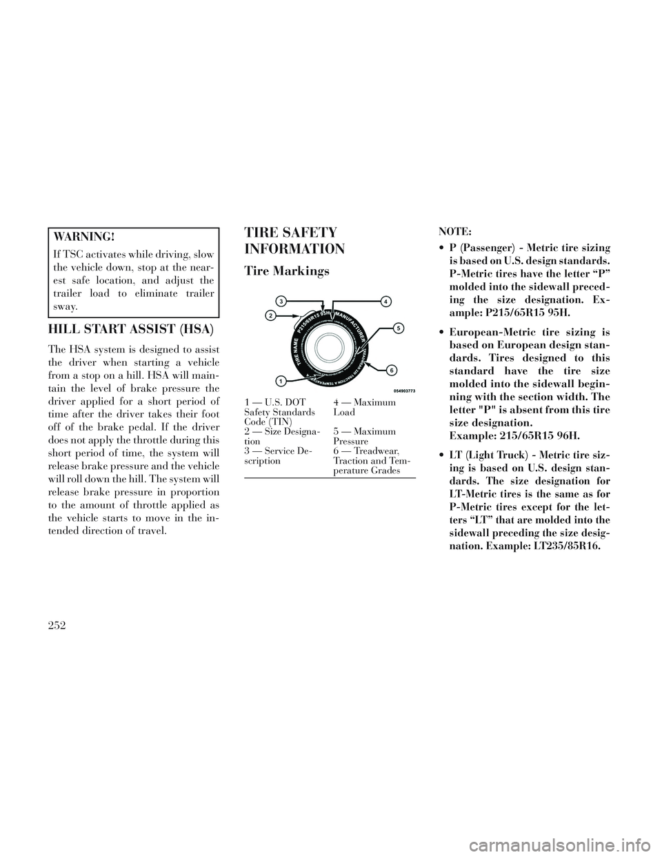
Tire Markings
NOTE:
P (Passenger) - Metric tire sizing
is based on U.S. design standards.
P-Metric tires have the letter “P”
molded into the sidewall preced-
ing the size designation. Ex-
ample: P215/65R15 95H.
European-Metric tire sizing isbased on European design stan-
dards. Tires designed to this
standard have the tire size
molded into the sidewall begin-
ning with the section width. The
letter "P" is absent from this tire
size designation.
Example: 215/65R15 96H.
LT (Light Truck) - Metric tire siz-
ing is based on U.S. design stan-
dards. The size designation for
LT-Metric tires is the same as for
P-Metric tires except for the let-
ters “LT” that are molded into the
sidewall preceding the size desig-
nation. Example: LT235/85R16.
1—U.S.DOT
Safety Standards
Code (TIN) 4 — Maximum
Load
2—
Size Designa-
tion5 — Maximum
Pressure
3 — Service De-
scription 6 — Treadwear,
Traction and Tem-
perature Grades
252