ECU Lancia Ypsilon 2002 Owner handbook (in English)
[x] Cancel search | Manufacturer: LANCIA, Model Year: 2002, Model line: Ypsilon, Model: Lancia Ypsilon 2002Pages: 191, PDF Size: 2.45 MB
Page 29 of 191

26
G
fig. 23
P4C00312
TRANSPORTING
CHILDREN SAFELY
For the best protection in the event
of a crash, all passengers must be
seated and wearing adequate restraint
systems.
This is especially relevant for chil-
dren.
A child’s head, in respect to that of
an adult, is larger and heavier in re-
lation to the body. Moreover the mus-
cular and bone structure is not fully
developed. For these reasons, children
require specific restraint systems, dif-
ferent to those required by adult pas-
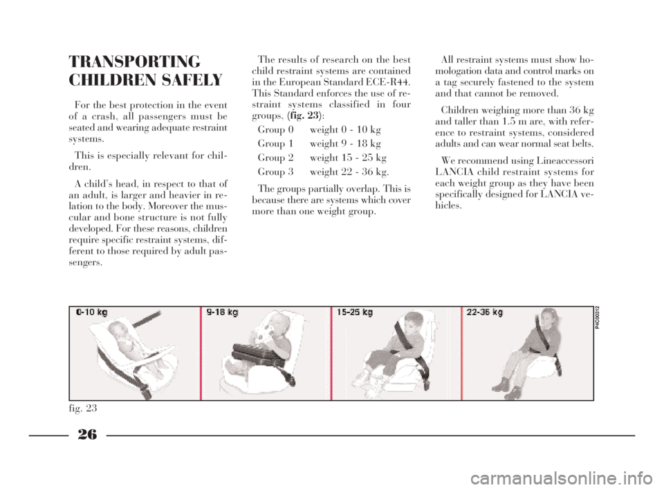
sengers.The results of research on the best
child restraint systems are contained
in the European Standard ECE-R44.
This Standard enforces the use of re-
straint systems classified in four
groups,(fig. 23):
Group 0 weight 0 - 10 kg
Group 1 weight 9 - 18 kg
Group 2 weight 15 - 25 kg
Group 3 weight 22 - 36 kg.
The groups partially overlap. This is
because there are systems which cover
more than one weight group.All restraint systems must show ho-
mologation data and control marks on
a tag securely fastened to the system
and that cannot be removed.
Children weighing more than 36 kg
and taller than 1.5 m are, with refer-
ence to restraint systems, considered
adults and can wear normal seat belts.
We recommend using Lineaccessori
LANCIA child restraint systems for
each weight group as they have been
specifically designed for LANCIA ve-
hicles.
4C001-067 ING 11-03-2008 11:57 Pagina 26
Page 30 of 191

27
G
fig. 24
P4C00310
fig. 25
P4C00311
We recommend sitting
children on the rear seat.
This is the most protected
position in the event of a crash.
Never fit child restraint systems in
the front passenger seat in vehicles
with a passenger airbag. The in-
flated airbag could cause even fa-
tal injury, regardless of the sever-
ity of the crash which triggered it
off.
Children can sit in the front pas-
senger seat in cars with passenger
side airbag only if the system has
been deactivated. In this case, al-
ways make sure that the amber in-
strument panel warning light is on
to confirm that the airbag has been
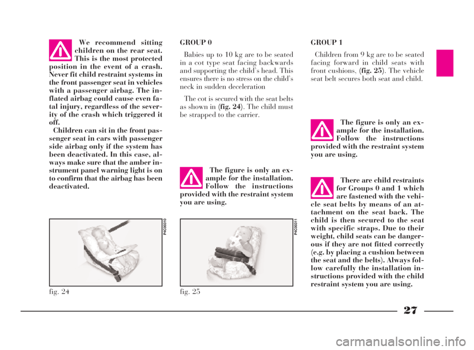
deactivated.GROUP 0
Babies up to 10 kg are to be seated
in a cot type seat facing backwards
and supporting the child’s head. This
ensures there is no stress on the child’s
neck in sudden deceleration
The cot is secured with the seat belts
as shown in (fig. 24). The child must
be strapped to the carrier.GROUP 1
Children from 9 kg are to be seated
facing forward in child seats with
front cushions, (fig. 25). The vehicle
seat belt secures both seat and child.
The figure is only an ex-
ample for the installation.
Follow the instructions
provided with the restraint system
you are using.
The figure is only an ex-
ample for the installation.
Follow the instructions
provided with the restraint system
you are using.
There are child restraints
for Groups 0 and 1 which
are fastened with the vehi-
cle seat belts by means of an at-
tachment on the seat back. The
child is then secured to the seat
with specific straps. Due to their
weight, child seats can be danger-
ous if they are not fitted correctly
(e.g. by placing a cushion between
the seat and the belts). Always fol-
low carefully the installation in-
structions provided with the child
restraint system you are using.
4C001-067 ING 11-03-2008 11:57 Pagina 27
Page 31 of 191

28
G
fig. 26
P4C00313
fig. 27
P4C00314
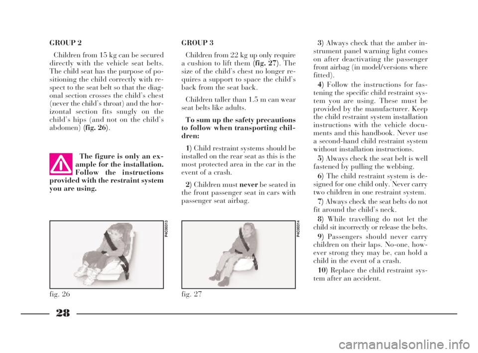
GROUP 2
Children from 15 kg can be secured
directly with the vehicle seat belts.
The child seat has the purpose of po-
sitioning the child correctly with re-
spect to the seat belt so that the diag-
onal section crosses the child’s chest
(never the child’s throat) and the hor-
izontal section fits snugly on the
child’s hips (and not on the child’s
abdomen)(fig. 26).GROUP 3
Children from 22 kg up only require
a cushion to lift them (fig. 27). The
size of the child’s chest no longer re-
quires a support to space the child’s
back from the seat back.
Children taller than 1.5 m can wear
seat belts like adults.
To sum up the safety precautions
to follow when transporting chil-
dren:
1)Child restraint systems should be
installed on the rear seat as this is the
most protected area in the car in the
event of a crash.
2)Children must neverbe seated in
the front passenger seat in cars with
passenger seat airbag.3)Always check that the amber in-
strument panel warning light comes
on after deactivating the passenger
front airbag (in model/versions where
fitted).
4)Follow the instructions for fas-
tening the specific child restraint sys-
tem you are using. These must be
provided by the manufacturer. Keep
the child restraint system installation
instructions with the vehicle docu-
ments and this handbook. Never use
a second-hand child restraint system
without installation instructions.
5)Always check the seat belt is well
fastened by pulling the webbing.
6)The child restraint system is de-
signed for one child only. Never carry
two children in one restraint system.
7)Always check the seat belts do not
fit around the child’s neck.
8)While travelling do not let the
child sit incorrectly or release the belts.
9)Passengers should never carry
children on their laps. No-one, how-
ever strong they may be, can hold a
child in the event of a crash.
10)Replace the child restraint sys-
tem after an accident. The figure is only an ex-
ample for the installation.
Follow the instructions
provided with the restraint system
you are using.
4C001-067 ING 11-03-2008 11:57 Pagina 28
Page 55 of 191

52
G
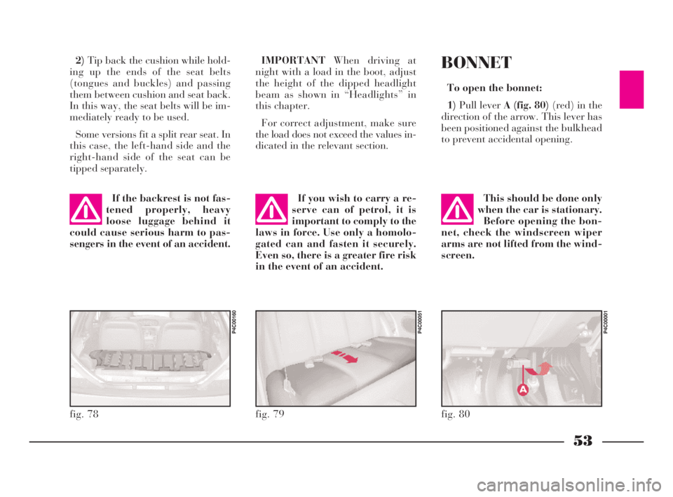
4)Fold the seat back forwards to
make a flat loading surface with the
boot floor (fig. 78).
If necessary, the cushion can also be
tilted(fig. 79). Consequently, before
releasing the seat back, lift the cush-
ion as shown and tip it against the
front seat backs; the rear seat back-
rest can then be released and tilted
forwards.
To return the seat to its normal po-
sition:
1)Return the seat back to the verti-
cal position and make sure it is prop-
erly locked into place; the red strip on
the hook-up button must disappear.
fig. 77
P4C00034
Removing the parcel shelf
If you wish to remove the parcel
shelf to extend the boot capacity, un-
hook the two tie-rods (one each side)
A (fig. 75)from the hooks B, then
pull the parcel shelf outwards so that
pinsCcome out.
The shelf can then be positioned be-
hind the front seats.INCREASING THE LOAD AREA
Proceed as follows:
1)Make sure that the side seat belts
A (fig. 76)have been inserted into the
corresponding bracket B.
2)Remove the rear head restraints
if required.
3)Release the seat back by pressing
buttonA (fig. 77)(one for each side)
located on the back seat back-rest
(even when a split back seat is fitted);
a red strip will appear on the short
side of the button (towards the inside
of the car) to indicate that it has been
released.
fig. 75
P4C00009
fig. 76
P4C00052
Heavy loads which are
not securely anchored
could seriously injure pas-
sengers in the event of an accident.
4C001-067 ING 11-03-2008 11:57 Pagina 52
Page 56 of 191

53
G
2)Tip back the cushion while hold-
ing up the ends of the seat belts
(tongues and buckles) and passing
them between cushion and seat back.
In this way, the seat belts will be im-
mediately ready to be used.
Some versions fit a split rear seat. In
this case, the left-hand side and the
right-hand side of the seat can be
tipped separately.IMPORTANTWhen driving at
night with a load in the boot, adjust
the height of the dipped headlight
beam as shown in “Headlights” in
this chapter.
For correct adjustment, make sure
the load does not exceed the values in-
dicated in the relevant section.
fig. 78
P4C00160
fig. 79
P4C00051
If the backrest is not fas-
tened properly, heavy
loose luggage behind it
could cause serious harm to pas-
sengers in the event of an accident.If you wish to carry a re-
serve can of petrol, it is
important to comply to the
laws in force. Use only a homolo-
gated can and fasten it securely.
Even so, there is a greater fire risk
in the event of an accident.
BONNET
To open the bonnet:
1)Pull lever A (fig. 80)(red) in the
direction of the arrow. This lever has
been positioned against the bulkhead
to prevent accidental opening.
fig. 80
P4C00001
This should be done only
when the car is stationary.
Before opening the bon-
net, check the windscreen wiper
arms are not lifted from the wind-
screen.
4C001-067 ING 11-03-2008 11:57 Pagina 53
Page 102 of 191

99
G
10)Ensure that the support surfaces
of the spare wheel are clean and free
from impurities which could succes-
sively cause the wheel bolts to loosen.
Mount the spare wheel so that the
holesI (fig. 4) coincide with the rela-
tive pinsL.
IMPORTANTDo not fit the wheel
cover on the space-saver spare wheel.
11)Tighten the 4 securing bolts.
12)Turn the jack handle to lower
the car, and remove the jack.
13)Tighten up the wheel bolts com-
pletely in criss-cross fashion following
the order shown in(fig. 5).
14)Put the punctured wheel in the
spare wheel compartment.The spare wheel is narrower than
normal wheels and must only be used
to travel to the nearest service station
so that the original tyre can be re-
paired.
Depending on whether the type of
wheels normally fitted to the car are
alloy or steel, the spare wheel (which
always has a steel rim) will differ in
construction so that it is compatible
with the wheel bolts which are specific
to each type of wheel.
If you wish to change the type of
wheel (alloy instead of steel and vice-
versa) the wheel bolts and a new
spare wheel must be employed.
Modifications or repairs
to the electrical system
carried out incorrectly and
without bearing the features of the
system in mind can cause mal-
functions with the risk of fire. REFITTING THE STANDARD
WHEEL
1)Following the above procedure,
raise the car and take off the space-
saver wheel.
4)Fit the wheel cover (1.2
16VM Nblueversion), mak-
ing sure that slit C (fig. 6)
corresponds with the inflation valve.
5)Insert the other three bolts, using
extensionF (fig. 2)(1.2
16VM Nblue
version).
6)Tighten the bolts using the spe-
cial wrench D (fig. 2).
fig. 8
P4C00404
4C090-119 ING 11-03-2008 12:00 Pagina 99
Page 104 of 191

101
fG
C Tubular bulbs
Release these bulbs from rela-
tive contacts to remove them.
D Halogen bulbs
Release the securing spring
from its seat to remove the
bulb.BULB Fig. 9 TYPE POWER
Main beam headlights
Dipped beam headlights
Front side lights
Front direction indicators
Side direction indicators
Rear direction indicators
Foglights
Reverse lights
Rear brake and side lights
Rear side lights
Rear fog lights
Third brake light
Number plate
Ceiling light (1.2 16VM Nblue- LS versions)
Ceiling light:
– with courtesy light
– with map light
BootD H3 12V-55W
D H7 12V-55W
A W5W 12V-5W
B PY21W 12V-21W
A W5W 12V-5W
B PY21W 12V-21W
D H1 12V-55W
B P21W 12V-21W
B R5W 12V-21/5W
B R5W 12V-21W
B P21W 12V-21W
A W5W 12V-5W
C C5W 12V-5W
C – 12V-10W
C – 12V-10W
A – 12V-6W
C C5W 12V-5W
4C090-119 ING 13-03-2008 12:51 Pagina 101
Page 105 of 191

102
fG
FRONT SIDE LIGHTS
To replace the 12V-5W bulb (type
W5W):
1)Remove the cover B (fig.10)by
turning partially in an anti-clockwise
direction.
2)Slide out bulb holder C (fig. 12)
by turning it slightly to make it easier
to release.
3)Remove the bulb.
4)Replace the press-fit bulb and re-
fit the bulb holder and cover.
fig. 12
P4C00025
HEADLIGHTS
To replace the halogen lights (12V-
55W):
1)Remove covers AandB (fig. 10)
by turning them partially in an anti-
clockwise direction.
2)Release the clips C-E (fig. 11)
and remove the burnt-out bulb D
(mainbeam headlight of type H3 with
printed wire already attached) or F
(dippedbeam headlight, type H7).
3)Insert the new bulb, making sure
it is positioned properly.
4)Reattach the securing clips and
close the covers.IF AN EXTERIOR
LIGHT BURNS OUT
fig. 10
P4C00027
fig. 11
P4C00026
Modifications or repairs
to the electrical system
carried out incorrectly and
without bearing the features of the
system in mind can cause mal-
functions with the risk of fire.
4C090-119 ING 13-03-2008 12:51 Pagina 102
Page 107 of 191

REAR LIGHT CLUSTER
1)From inside the car boot, lift the
carpeting and undo screw A (fig. 19)
securing the light cluster.
2)Remove the light cluster B.
3)Replace the burnt-out bulb by
pushing it slightly and turning anti-
clockwise.
Bulbs in (fig. 20):
C - 12V-21W (orange) (type PY21W)
for the direction indicators.
D - 12-21W (type P21W) for the re-
versing lights.
104
fG
3)Remove the bulb holder B
(fig. 16)fromCin the lens.
4)Remove press-fit bulb Dand re-
place it.
5)Refit the bulb holder into Cand
then fit the lens.
FRONT FOGLIGHTS
To replace the halogen bulb 12V-
55W (type H1):
1)Turn the wheels to the right to get
at the left light, and to the left to get
at the right light.
2)Unscrew screw A (fig. 17)in the
cover on the wheelarch.3)Turn cover Bin an anticlockwise
direction.
4)Release clip D (fig. 18)and re-
move bulbC.
5)Release the clip Dand screw
coverBback in.
fig. 16
P4C00383
fig. 17
P4C00152
fig. 18
P4C00406
fig. 19
P4C00038
4C090-119 ING 13-03-2008 12:51 Pagina 104
Page 109 of 191

106
fG
IF AN INTERIOR
LIGHT BURNS OUTrounding it, by inserting the tip of a
screwdriver between the cover frame
and the second frame as illustrated in
(fig. 25).
CEILING LIGHT
(all other versions)
To replace a bulb:
1)Remove the 2 plastic caps Aand
release cover B (fig. 26).
2)Unscrew the 4 screws securing the
ceiling light unit that can be seen.
3)Press tab A (fig. 27)to open the
bulb holder.
4)Replace the burnt-out bulb.
B- 12V-10W bulb for courtesy light.
C- 12V-6W bulb for map-reading
light. NUMBER PLATE LIGHTS
To replace the 12V-5W (type C5W)
bulb, unscrew the securing screws A
(fig. 24)and remove the lens.
CEILING LIGHT (1.2
16VM Nblue
- LS)
To replace the 12V-10W bulb in the
ceiling lamp, remove the transparent
cover, together with the frame sur-Modifications or repairs
to the electrical system
carried out incorrectly and
without bearing the features of the
system in mind can cause mal-
functions with the risk of fire.
fig. 24
P4C00147
fig. 25
P4C00164
fig. 26
P4C00064
4C090-119 ING 13-03-2008 12:51 Pagina 106