clock Lancia Ypsilon 2002 Owner handbook (in English)
[x] Cancel search | Manufacturer: LANCIA, Model Year: 2002, Model line: Ypsilon, Model: Lancia Ypsilon 2002Pages: 191, PDF Size: 2.45 MB
Page 32 of 191
29
G
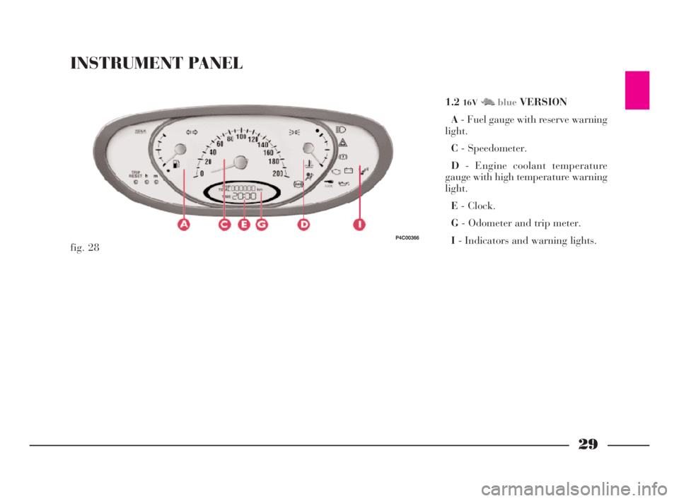
INSTRUMENT PANEL
1.216VM NblueVERSION
A- Fuel gauge with reserve warning
light.
C- Speedometer.
D- Engine coolant temperature
gauge with high temperature warning
light.
E- Clock.
G- Odometer and trip meter.
I- Indicators and warning lights.
fig. 28
P4C00366
4C001-067 ING 11-03-2008 11:57 Pagina 29
Page 33 of 191

30
G
LS-LX VERSIONS
A- Fuel gauge with reserve warning
light.
B- Rev counter.
C- Speedometer.
D- Engine coolant temperature gauge
with high temperature warning light.
E- Clock.
F- Outside temperature gauge.
G- Odometer.
H- Trip meter.
I- Indicators and warning lights.
fig. 29
P4C00367
1.216VM NredVERSION
A- Fuel gauge with reserve warning
light.
B- Rev counter.
C- Speedometer.
D- Engine coolant temperature gauge
with high temperature warning light.
E- Clock.
F- Outside temperature gauge.
G- Odometer.
H- Trip meter.
I- Indicators and warning lights.
fig. 30
P4C00368
4C001-067 ING 11-03-2008 11:57 Pagina 30
Page 35 of 191
32
G
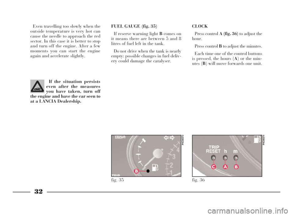
CLOCK
Press control A (fig. 36)to adjust the
hour.
Press control Bto adjust the minutes.
Each time one of the control buttons
is pressed, the hours (A) or the min-
utes (B) will move forwards one unit. Even travelling too slowly when the
outside temperature is very hot can
cause the needle to approach the red
sector. In this case it is better to stop
and turn off the engine. After a few
moments you can start the engine
again and accelerate slightly.FUEL GAUGE (fig. 35)
If reserve warning light Bcomes on
it means there are between 5 and 8
litres of fuel left in the tank.
Do not drive when the tank is nearly
empty: possible changes in fuel deliv-
ery could damage the catalyser.
If the situation persists
even after the measures
you have taken, turn off
the engine and have the car seen to
at a LANCIA Dealership.
fig. 36
P4C00374
fig. 35
P4C00373
4C001-067 ING 11-03-2008 11:57 Pagina 32
Page 70 of 191
67
G
Only change the fuel filler cap with
a genuine spare part in order not to
compromise the petrol fume recovery
system.FUEL TANK CAP
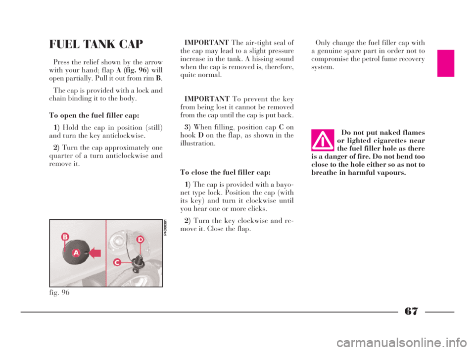
Press the relief shown by the arrow
with your hand; flapA (fig. 96)will
open partially. Pull it out from rim B.
The cap is provided with a lock and
chain binding it to the body.
To open the fuel filler cap:
1)Hold the cap in position (still)
and turn the key anticlockwise.
2)Turn the cap approximately one
quarter of a turn anticlockwise and
remove it.IMPORTANTThe air-tight seal of
the cap may lead to a slight pressure
increase in the tank. A hissing sound
when the cap is removed is, therefore,
quite normal.
IMPORTANTTo prevent the key
from being lost it cannot be removed
from the cap until the cap is put back.
3)When filling, position cap Con
hookDon the flap, as shown in the
illustration.
To close the fuel filler cap:
1)The cap is provided with a bayo-
net type lock. Position the cap (with
its key) and turn it clockwise until
you hear one or more clicks.
2)Turn the key clockwise and re-
move it. Close the flap.Do not put naked flames
or lighted cigarettes near
the fuel filler hole as there
is a danger of fire. Do not bend too
close to the hole either so as not to
breathe in harmful vapours.
fig. 96
P4C00381
4C001-067 ING 11-03-2008 11:57 Pagina 67
Page 105 of 191

102
fG
FRONT SIDE LIGHTS
To replace the 12V-5W bulb (type
W5W):
1)Remove the cover B (fig.10)by
turning partially in an anti-clockwise
direction.
2)Slide out bulb holder C (fig. 12)
by turning it slightly to make it easier
to release.
3)Remove the bulb.
4)Replace the press-fit bulb and re-
fit the bulb holder and cover.
fig. 12
P4C00025
HEADLIGHTS
To replace the halogen lights (12V-
55W):
1)Remove covers AandB (fig. 10)
by turning them partially in an anti-
clockwise direction.
2)Release the clips C-E (fig. 11)
and remove the burnt-out bulb D
(mainbeam headlight of type H3 with
printed wire already attached) or F
(dippedbeam headlight, type H7).
3)Insert the new bulb, making sure
it is positioned properly.
4)Reattach the securing clips and
close the covers.IF AN EXTERIOR
LIGHT BURNS OUT
fig. 10
P4C00027
fig. 11
P4C00026
Modifications or repairs
to the electrical system
carried out incorrectly and
without bearing the features of the
system in mind can cause mal-
functions with the risk of fire.
4C090-119 ING 13-03-2008 12:51 Pagina 102
Page 106 of 191

103
fG
FRONT DIRECTION
INDICATORS
To replace the 12V-21W bulb (type
PY21W):
1)Release spring clip A (fig. 13)
from support Bby turning in the di-
rection of the arrow.
2)Pull out the lens unit from the
front.
3)The bulb holder Cis connected to
the lens unit. To remove it, turn it
slightly.4)Remove bulbE (fig. 14), by push-
ing it gently and turning it in an an-
ticlockwise direction.
5)Replace the bulb, then refit the
bulb holder to the lens unit.
6)Reposition the lens unit, by intro-
ducing the two tabs Dinto the guides
at the side of the headlamp.
7)Reattach spring clip A.DIRECTION INDICATOR
REPEATERS
To replace the 12V-5W bulb (type
W5W):
1)Push the lens A (fig. 15)in the di-
rection of the arrow to release the fas-
tening tab. Be careful not to damage
the bodywork.
2)Take the unit out.
fig. 13
P4C00029
fig. 14
P4C00405
fig. 15
P4C00382
4C090-119 ING 13-03-2008 12:51 Pagina 103
Page 107 of 191

REAR LIGHT CLUSTER
1)From inside the car boot, lift the
carpeting and undo screw A (fig. 19)
securing the light cluster.
2)Remove the light cluster B.
3)Replace the burnt-out bulb by
pushing it slightly and turning anti-
clockwise.
Bulbs in (fig. 20):
C - 12V-21W (orange) (type PY21W)
for the direction indicators.
D - 12-21W (type P21W) for the re-
versing lights.
104
fG
3)Remove the bulb holder B
(fig. 16)fromCin the lens.
4)Remove press-fit bulb Dand re-
place it.
5)Refit the bulb holder into Cand
then fit the lens.
FRONT FOGLIGHTS
To replace the halogen bulb 12V-
55W (type H1):
1)Turn the wheels to the right to get
at the left light, and to the left to get
at the right light.
2)Unscrew screw A (fig. 17)in the
cover on the wheelarch.3)Turn cover Bin an anticlockwise
direction.
4)Release clip D (fig. 18)and re-
move bulbC.
5)Release the clip Dand screw
coverBback in.
fig. 16
P4C00383
fig. 17
P4C00152
fig. 18
P4C00406
fig. 19
P4C00038
4C090-119 ING 13-03-2008 12:51 Pagina 104
Page 113 of 191
110
fG
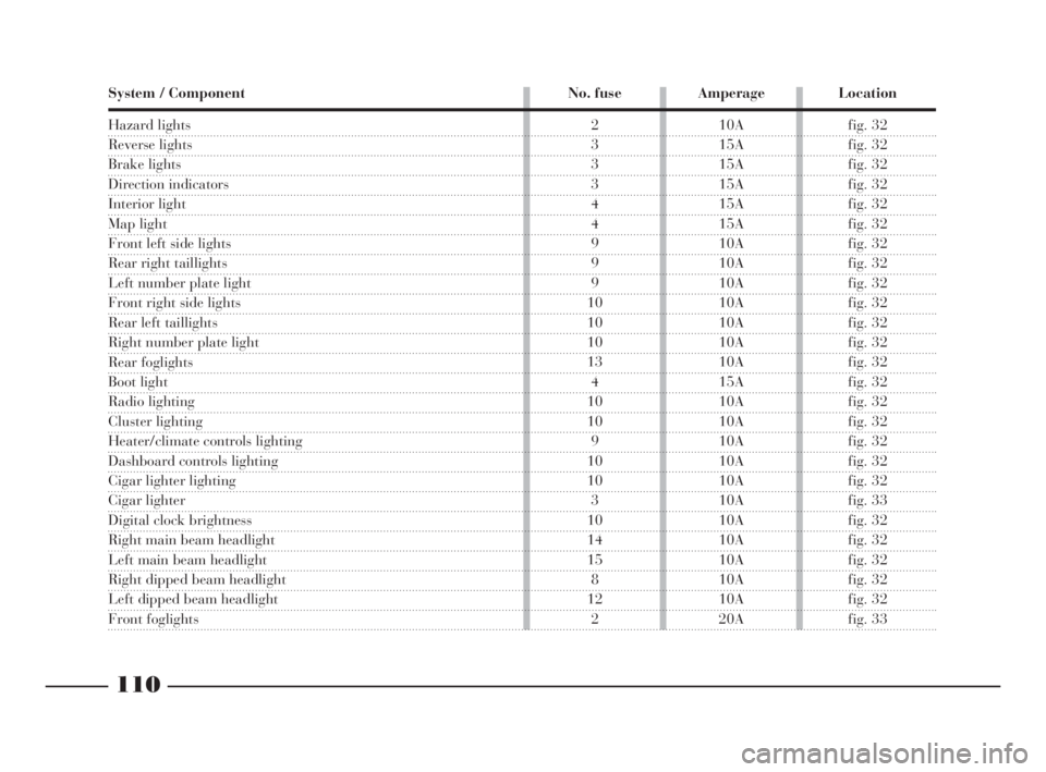
System / Component No. fuse Amperage Location
Hazard lights
Reverse lights
Brake lights
Direction indicators
Interior light
Map light
Front left side lights
Rear right taillights
Left number plate light
Front right side lights
Rear left taillights
Right number plate light
Rear foglights
Boot light
Radio lighting
Cluster lighting
Heater/climate controls lighting
Dashboard controls lighting
Cigar lighter lighting
Cigar lighter
Digital clock brightness
Right main beam headlight
Left main beam headlight
Right dipped beam headlight
Left dipped beam headlight
Front foglights
2 10A fig. 32
3 15A fig. 32
3 15A fig. 32
3 15A fig. 32
4 15A fig. 32
4 15A fig. 32
9 10A fig. 32
9 10A fig. 32
9 10A fig. 32
10 10A fig. 32
10 10A fig. 32
10 10A fig. 32
13 10A fig. 32
4 15A fig. 32
10 10A fig. 32
10 10A fig. 32
9 10A fig. 32
10 10A fig. 32
10 10A fig. 32
3 10A fig. 33
10 10A fig. 32
14 10A fig. 32
15 10A fig. 32
8 10A fig. 32
12 10A fig. 32
2 20A fig. 33
4C090-119 ING 13-03-2008 12:51 Pagina 110
Page 180 of 191
177
fdG
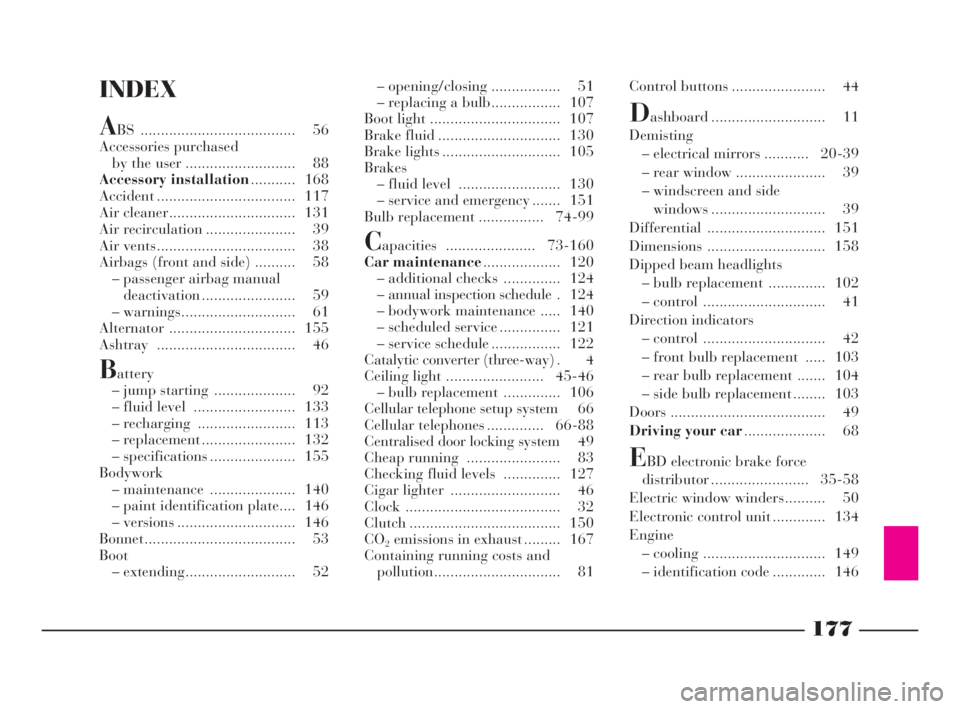
INDEX
ABS ...................................... 56
Accessories purchased
by the user ........................... 88
Accessory installation........... 168
Accident .................................. 117
Air cleaner............................... 131
Air recirculation ...................... 39
Air vents.................................. 38
Airbags (front and side) .......... 58
– passenger airbag manual
deactivation ....................... 59
– warnings............................ 61
Alternator ............................... 155
Ashtray .................................. 46
Battery
– jump starting .................... 92
– fluid level ......................... 133
– recharging ........................ 113
– replacement ....................... 132
– specifications ..................... 155
Bodywork
– maintenance ..................... 140
– paint identification plate.... 146
– versions ............................. 146
Bonnet..................................... 53
Boot
– extending........................... 52– opening/closing ................. 51
– replacing a bulb................. 107
Boot light ................................ 107
Brake fluid .............................. 130
Brake lights ............................. 105
Brakes
– fluid level ......................... 130
– service and emergency ....... 151
Bulb replacement ................ 74-99
Capacities ...................... 73-160
Car maintenance................... 120
– additional checks .............. 124
– annual inspection schedule . 124
– bodywork maintenance ..... 140
– scheduled service ............... 121
– service schedule ................. 122
Catalytic converter (three-way) . 4
Ceiling light ........................ 45-46
– bulb replacement .............. 106
Cellular telephone setup system 66
Cellular telephones .............. 66-88
Centralised door locking system 49
Cheap running ....................... 83
Checking fluid levels .............. 127
Cigar lighter ........................... 46
Clock ...................................... 32
Clutch ..................................... 150
CO
2emissions in exhaust ......... 167
Containing running costs and
pollution............................... 81Control buttons ....................... 44
Dashboard ............................ 11
Demisting
– electrical mirrors ........... 20-39
– rear window ...................... 39
– windscreen and side
windows ............................ 39
Differential ............................. 151
Dimensions ............................. 158
Dipped beam headlights
– bulb replacement .............. 102
– control .............................. 41
Direction indicators
– control .............................. 42
– front bulb replacement ..... 103
– rear bulb replacement ....... 104
– side bulb replacement ........ 103
Doors ...................................... 49
Driving your car.................... 68
EBD electronic brake force
distributor ........................ 35-58
Electric window winders.......... 50
Electronic control unit ............. 134
Engine
– cooling .............................. 149
– identification code ............. 146
4C177-184 Indice ING 13-03-2008 13:31 Pagina 177