tow Lancia Ypsilon 2002 Owner handbook (in English)
[x] Cancel search | Manufacturer: LANCIA, Model Year: 2002, Model line: Ypsilon, Model: Lancia Ypsilon 2002Pages: 191, PDF Size: 2.45 MB
Page 128 of 191

125
G
IMPORTANT - Battery
You should check the battery charge
preferably at the beginning of the
winter to avoid the possibility of the
electrolyte freezing up.
This check should be performed
more frequently if the car is mainly
used for short trips, or if it is fitted
with accessories that absorb energy
even when the ignition key is re-
moved, especially if they are after-
market accessories.
You should check the battery fluid
(electrolyte) level more frequently
than shown in the Service Schedule
(see “Car maintenance”) if the car is
used in hot climates or particularly
demanding conditions. IMPORTANT - Engine oil
Change the engine oil more fre-
quently than indicated in the Service
Schedule, if the car is normally driven
in one of the following particularly se-
vere conditions:
– towing a trailer or caravan
– on dusty roads
– short, repetitive trips (less than 7
or 8 kilometres) in outside tempera-
tures below zero
– engines that are frequently left to
idle or drive slowly over long dis-
tances.
IMPORTANT - Air cleaner
Change the air cleaner more often
than indicated in the Service Sched-
ule if you use the car on dusty roads.
If you are in doubt about how often
the engine oil or the air cleaner should
be changed in relation to how you use
the car, contact a LANCIA Dealer-
ship.IMPORTANT - Pollen filter
If the car is often used in dusty or
highly polluted areas, you should
change the pollen filtering element
more frequently, especially if you no-
tice that the amount of air entering
the passenger compartment is re-
duced.
IMPORTANT - Remote control
If the LED on the remote control
unit flashes only once when you press
the remote control button, you need
to replace the batteries.
4C120-143 ING 11-03-2008 12:01 Pagina 125
Page 160 of 191

157
G
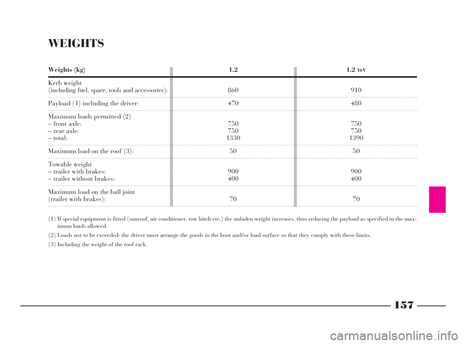
WEIGHTS
Weights (kg)
Kerb weight
(including fuel, spare, tools and accessories):
Payload (1) including the driver:
Maximum loads permitted (2)
– front axle:
– rear axle:
– total:
Maximum load on the roof (3):
Towable weight
– trailer with brakes:
– trailer without brakes:
Maximum load on the ball joint
(trailer with brakes):1.2
16V
910
480
750
750
1390
50
900
400
70 1.2
860
470
750
750
1330
50
900
400
70
(1) If special equipment is fitted (sunroof, air conditioner, tow hitch etc.) the unladen weight increases, thus reducing the payload as specified in the max-
imum loads allowed.
(2) Loads not to be exceeded: the driver must arrange the goods in the boot and/or load surface so that they comply with these limits.
(3) Including the weight of the roof rack.
4C144-167 ING 11-03-2008 12:02 Pagina 157
Page 171 of 191

ACCESSORY INSTALLATION
Genuine Lancia accessories have been designed
with the Lancia Y specifically in mind and have
been selected and tested on the car. They are easy
to use, reliable and practical: qualities that lead
to enhanced comfort and safety under all driving
conditions.
For child safety, the child seats in the Lineac-
cessori Lancia line meet the strictest current Eu-
ropean standards.
You can find the Lancia accessories described in
a catalogue available from Lancia Dealerships.
Just ask the staff to give you all the details.
The following pages show diagrams and give in-
structions for correctly fitting a number of acces-
sories. Installation must always be entrusted to the
experts. Lancia has specially trained its Dealer-
ship staff for work on the Lancia Y.SOUND SYSTEM/RADIO NAVIGATION
SYSTEM......................................................... 169
TOW HITCH .................................................. 172
RF REMOTE CONTROL:
MINISTERIAL HOMOLOGATION .................. 175
168
G
4C168-176 ING 11-03-2008 12:03 Pagina 168
Page 175 of 191

172
G
ELECTRICAL CONNECTION
DIAGRAM (fig. 4)
1- Connection on the branching box
for powering the relays
2- Terminal box
3- Left taillight
4- Relay for the power supply of the
trailer’s left-hand direction indicator
5- Relay for the power supply of the
trailer’s right-hand direction indicator
6- Right taillight
7- 7-pole socket
8- Rear left grounding point
9- Connection between dashboard
cables and rear cables
10- 7.5A fuse
List of cable colour codes
B=White - G- Yellow - L=Blue- M=Brown- N=Black- R=Red- V=Green
TOW HITCH
fig. 4
P4C00170
4C168-176 ING 11-03-2008 12:03 Pagina 172
Page 176 of 191

173
G
For mechanical connections, the fol-
lowing must be used:
– “CUNA 501” 1
stclass ball coupling
(CUNA NC 138-40 table);
– “CUNA 501” 1
stclass socket cou-
pling (CUNA NC 438-40 table).For the electric connection a 7-pole,
12 Volt coupling must be used
(CUNA UNI 9128).
The electric coupling must be fixed
on a special mount to be attached to
the ball coupling.
The electrical functions for the cou-
pling must be connected as illustrated
in(fig. 5).
In addition to the electrical connec-
tions (illustrated in the diagram that
follows), only the lead for powering
an electric brake and the lead to
power a light inside the trailer not ex-
ceeding 15W may be connected to the
car’s electrical system.
The electric brake must be powered
directly from the battery by means of
a lead with a cross-section no less
than 2.5 sq. mm.
Location of the components
on the car:
1.Left taillight (rear foglight con-
nection) - 2.Right taillight (brake
lights connection) - 3.Pole socket -
4.Trailer direction indicators power
supply relays - 5.High-amp fusebox
-6.Branching box. TOW HITCH INSTALLATION
(fig. 5)
The tow hitch must be fixed to the
body by an expert in accordance with
the following instructions and with
any additional instructions or infor-
mation provided by the tow hitch
manufacturer.
fig. 5
P4C00416
4C168-176 ING 11-03-2008 12:03 Pagina 173
Page 177 of 191

174
G
The underbody plate must be wider
than the plate in the boot. Further-
more, the edge of the plate must be
turned up to avoid sharp corners
coming into contact with the body.
The tow hitch must be anchored to
the body without any drilling or trim-
ming of the rear bumper that would
be visible when the tow hitch is re-
moved.
IMPORTANTA clearly visible plate
of a suitable size and made of suitable
material saying:
MAX LOAD ON THE BALL
COUPLING 70 kg
must be fixed at the height of the ball
coupling.
FITTING INSTRUCTIONS
The body of the tow hitch (fig. 6)
must be fixed using 7 M10 screws at
the points indicated with the sym-
bol
Ø.All the anchorage points must have
suitable internal reinforcements made
of steel, 3 mm thick
Æ.After installation, the
holes for the retaining
screws must be sealed to
prevent the infiltration of exhaust
gases.
(*) Alternative value according to the tow hitch fitted.
fig. 6
P4C00307
Min. area in contact with the plates: 150 cm2
Spare wheel
compartment flat centre
Outer rear
wall line
Ground
Min. area in contact
with the plates: 176 cm
2Vehicle centreline
(vehicle fully laden)Vehicle
centreline
Spare wheel
centre
Seen from X
Seen from A
4C168-176 ING 11-03-2008 12:03 Pagina 174
Page 183 of 191

180
fdG
Three-way catalytic converter . 4
Tools ....................................... 96
Top speeds .............................. 156
Towing a trailer
– tow hitch installation ... 172-174
– warnings .......................... 84
Towing the car ........................ 116
Transmission ratios ................. 150
Transporting children in safety 26
Tyre pressure .............. 74-136-163
Tyres...................... 74-94-136-153
Useful accessories .................. 89
Ventilation ........................... 39
Warning lights
– ABS anti-locking system
failure................................ 35
– airbag failure ..................... 34
– brake light failure .............. 36
– direction indicators ............ 36
– doors not closed properly ... 34
– EOBD self-diagnostic
system ............................... 35
– external lights .................... 36
– handbrake on ................... 34
– hazard lights...................... 35
– Lancia CODE ................... 35
– low battery recharging ....... 34
– low brake fluid .................. 34Warning lights
– low engine oil pressure....... 34
Warning lights
– main beam headlights........ 36
– passenger airbag off .......... 36
Washer fluid level.................... 129
Washer nozzles ........................ 139
Weights ................................... 157
Wheel
– replacing a wheel ............... 94
– spare ........................... 96-154
Wheel geometry (toe-in) ......... 155
Wheel rims .............................. 153
Windows (cleaning )................ 142
Windows (rear) ....................... 47
Windscreen washer
– control .............................. 42
– fluid level ......................... 129
Windscreen wiper
– control ............................. 42
– blades ................................ 138
Windscreen wiper
– nozzles............................... 139
Wiper blades ........................... 138
4C177-184 Indice ING 13-03-2008 13:31 Pagina 180