ad blue Lancia Ypsilon 2002 Owner handbook (in English)
[x] Cancel search | Manufacturer: LANCIA, Model Year: 2002, Model line: Ypsilon, Model: Lancia Ypsilon 2002Pages: 191, PDF Size: 2.45 MB
Page 32 of 191

29
G
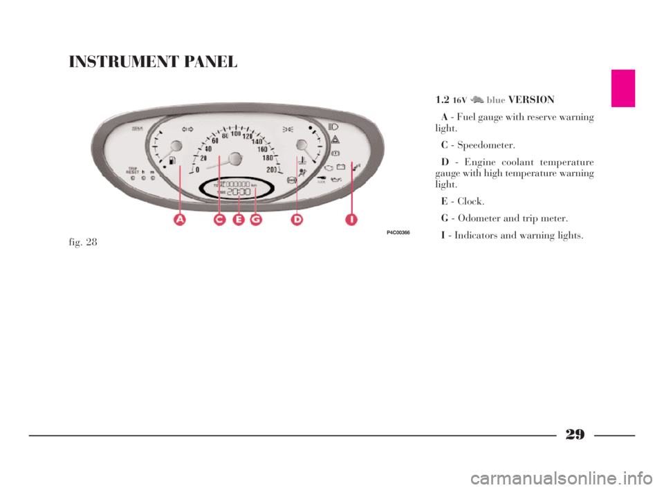
INSTRUMENT PANEL
1.216VM NblueVERSION
A- Fuel gauge with reserve warning
light.
C- Speedometer.
D- Engine coolant temperature
gauge with high temperature warning
light.
E- Clock.
G- Odometer and trip meter.
I- Indicators and warning lights.
fig. 28
P4C00366
4C001-067 ING 11-03-2008 11:57 Pagina 29
Page 34 of 191

31
G
INSTRUMENTS
SPEEDOMETER (fig. 31)ODOMETER AND TRIP
METER
For LS-LX - 1.216VM M Nredver-
sions(fig. 32)
A- Odometer.
B- Trip meter.
Press “Reset” button C (fig. 36)to
reset.
For the 1.2
16VM Nblueversion(fig.
33), only the odometer is displayed;
to display the trip meter, press button
C (fig. 36)slightly and release.
Press button C (fig. 36)for more
than 3 seconds to reset the trip
odometer.
Press button C (fig. 36) again to re-
turn to the odometer display.COOLANT TEMPERATURE
GAUGE (fig. 34)
If warning lamp Alights up, it
means that the engine coolant is too
hot.
Under normal conditions, the needle
of the temperature gauge should be-
tween 1/4 and 3/4 of the scale. If it
approaches the red section it means
the engine is being overtaxed and you
should reduce your demands on it.
IMPORTANTThe gauge will point
to low temperature and the excessive
temperature warning light Awill
come on to indicate a fault in the sys-
tem. Contact a LANCIA Dealership
to have the system checked.
fig. 32
P4C00370
fig. 33
P4C00371
fig. 31
P4C00369
fig. 34
P4C00372
4C001-067 ING 11-03-2008 11:57 Pagina 31
Page 36 of 191

33
G
REV COUNTER (fig. 39)
If the needle is in the red zone it
shows your car’s engine is over-
revving. This is only acceptable for a
few moments.
IMPORTANTThe electronic injec-
tion control system progressively
blocks the flow of fuel when the
pointer goes into the red zone leading
to a progressive loss of engine power.
fig. 37
P4C00375
fig. 38
P4C00376
–(fig. 37)- 1.2 16VM M Nblueversion.
–(fig. 38)- LS - LX - 1.2
16VMMN
red
versions.OUTSIDE TEMPERATURE
GAUGE (fig. 40)
The correct temperature reading is
given when the car is travelling.
fig. 40
P4C00378
When the temperature
displayed is near zero,
take great care as there is
the risk of ice on the road.
fig. 39
P4C00377
4C001-067 ING 11-03-2008 11:57 Pagina 33
Page 39 of 191

36
G
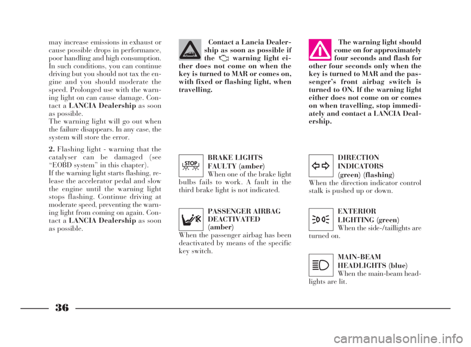
DIRECTION
INDICATORS
(green) (flashing)
When the direction indicator control
stalk is pushed up or down.
y
EXTERIOR
LIGHTING (green)
When the side-/taillights are
turned on.
3
MAIN-BEAM
HEADLIGHTS (blue)
When the main-beam head-
lights are lit.
1
may increase emissions in exhaust or
cause possible drops in performance,
poor handling and high consumption.
In such conditions, you can continue
driving but you should not tax the en-
gine and you should moderate the
speed. Prolonged use with the warn-
ing light on can cause damage. Con-
tact a LANCIA Dealershipas soon
as possible.
The warning light will go out when
the failure disappears. In any case, the
system will store the error.
2.Flashing light - warning that the
catalyser can be damaged (see
“EOBD system” in this chapter).
If the warning light starts flashing, re-
lease the accelerator pedal and slow
the engine until the warning light
stops flashing. Continue driving at
moderate speed, preventing the warn-
ing light from coming on again. Con-
tact a LANCIA Dealershipas soon
as possible.PASSENGER AIRBAG
DEACTIVATED
(amber)
When the passenger airbag has been
deactivated by means of the specific
key switch.The warning light should
come on for approximately
four seconds and flash for
other four seconds only when the
key is turned to MAR and the pas-
senger’s front airbag switch is
turned to ON. If the warning light
either does not come on or comes
on when travelling, stop immedi-
ately and contact a LANCIA Deal-
ership.Contact a Lancia Dealer-
ship as soon as possible if
the warning light ei-
ther does not come on when the
key is turned to MAR or comes on,
with fixed or flashing light, when
travelling.
BRAKE LIGHTS
FAULTY (amber)
When one of the brake light
bulbs fails to work. A fault in the
third brake light is not indicated.
T
4C001-067 ING 11-03-2008 11:57 Pagina 36
Page 42 of 191

39
G
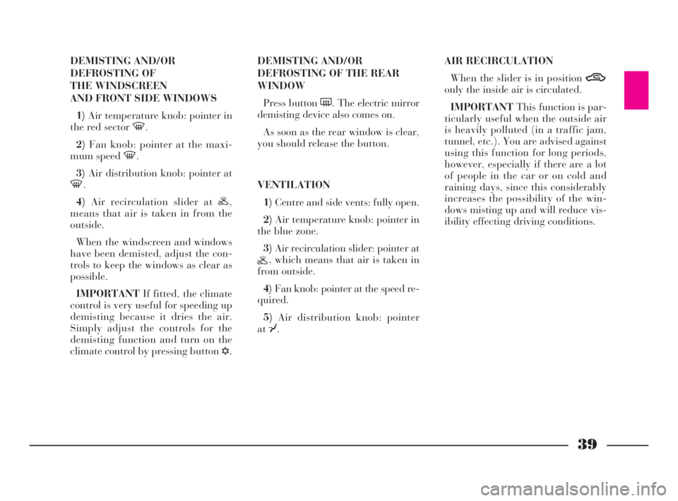
DEMISTING AND/OR
DEFROSTING OF
THE WINDSCREEN
AND FRONT SIDE WINDOWS
1)Air temperature knob: pointer in
the red sector -.
2)Fan knob: pointer at the maxi-
mum speed -.
3)Air distribution knob: pointer at
-.
4)Air recirculation slider at H,
means that air is taken in from the
outside.
When the windscreen and windows
have been demisted, adjust the con-
trols to keep the windows as clear as
possible.
IMPORTANTIf fitted, the climate
control is very useful for speeding up
demisting because it dries the air.
Simply adjust the controls for the
demisting function and turn on the
climate control by pressing button
√.DEMISTING AND/OR
DEFROSTING OF THE REAR
WINDOW
Press button (. The electric mirror
demisting device also comes on.
As soon as the rear window is clear,
you should release the button.
VENTILATION
1)Centre and side vents: fully open.
2)Air temperature knob: pointer in
the blue zone.
3)Air recirculation slider: pointer at
H, which means that air is taken in
from outside.
4)Fan knob: pointer at the speed re-
quired.
5)Air distribution knob: pointer
at¥.AIR RECIRCULATION
When the slider is in position T
only the inside air is circulated.
IMPORTANTThis function is par-
ticularly useful when the outside air
is heavily polluted (in a traffic jam,
tunnel, etc.). You are advised against
using this function for long periods,
however, especially if there are a lot
of people in the car or on cold and
raining days, since this considerably
increases the possibility of the win-
dows misting up and will reduce vis-
ibility effecting driving conditions.
4C001-067 ING 11-03-2008 11:57 Pagina 39
Page 43 of 191

40
G
CLIMATE CONTROL
SYSTEM
The climate control system is ad-
justed manually.
CONTROLS (fig. 45)
A- Air temperature knob (mixture
of warm and cold air).
B- Fan knob.
C- Air distribution knob.
D- Air recirculation slider, to elim-
inate external air.IMPORTANTThe recirculation
function allows to cool the air faster.
It is particularly useful when the out-
side air is heavily polluted (in a traf-
fic jam, tunnel, etc.). You are advised
against using this function for long
periods, however, especially if there
are a lot of people in the car or on
cold and raining days, since this con-
siderably increases the possibility of
the windows misting up and will re-
duce visibility effecting driving con-
ditions.
E- Climate control on/off switch.
When the climate control system is
on, the fan will automatically come on
at the first speed.COOLING
1)Air temperature knob: pointer in
the blue sector.
2)Climate control system: press
switch
√and move the air recircula-
tion slider to T.
3)Fan knob: pointer at required
speed.
4)Air distribution knob: pointer at
¥.
To reduce the cooling effect: move
the air recirculation slider to H, in-
crease the temperature and decrease
the fan speed.
fig. 45
P4C00326
The system uses R134a
refrigerating liquid. If it
accidentally leaks it will
not damage the environment.
Never use R12 fluid as it is incom-
patible with the system’s compo-
nents and also contains CFC.
4C001-067 ING 11-03-2008 11:57 Pagina 40
Page 77 of 191

LIGHT BULBS
Dipped beam headlights: 12V-55W.
Main beam headlights: 12V-55W.
Side and taillights: 12V-5W.
Front foglights: 12V-55W.
Front direction indicators: 12V-21W.
Rear direction indicators: 12V-21W.
Side direction indicators: 12V-5W.
Stop/taillights: 12V-21/5W.Reversing lights: 12V-21W.
Rear foglights: 12V-21W.
Number plate lights: 12V-5W.
Ceiling lights: 12V-10W.
Map reading light: 12V-6W
(LX version).
Boot light: 12V-10W.
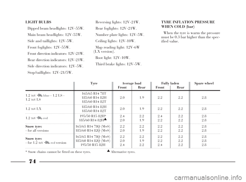
Third brake lights: 12V-5W.TYRE INFLATION PRESSURE
WHEN COLD (bar)
When the tyre is warm the pressure
must be 0.3 bar higher than the spec-
ified value.
74
G
TyreAverage loadFully laden Spare wheel
Front Rear Front Rear
1.2
16VM Nblue- 1.2 LS - 165/65 R14 78T
1.2
16VLS185/60 R14 82H 2.0 1.9 2.2 2.2 2.8185/60 R14 82T
1.2
16VLX185/60 R14 82H
2.0 1.9 2.2 2.2 2.8185/60 R14 82T
1.2
16VM Nred195/50 R15 82H* 2.4 2.2 2.4 2.2 2.8
185/60 R14 82H▲
2.0 1.9 2.2 2.2 2.8
Snow tyre:165/65 R14 78Q (M+S) 2.2 2.2 2.2 2.2 2.8
- for all versions 185/60 R14 82Q (M+S) 2.0 1.9 2.2 2.2 2.8
Snow tyre:165/65 R14 78Q (M+S) 2.2 2.2 2.2 2.2 2.8
- for 1.2
16VM Nredversion185/60 R14 82Q (M+S) 2.0 1.9 2.2 2.2 2.8195/50 R15 82H 2.4 2.2 2.4 2.2 2.8
* Snow chains cannot be fitted on these tyres.▲
Alternative tyres.
4C068-089 ING 11-03-2008 11:59 Pagina 74
Page 102 of 191

99
G
10)Ensure that the support surfaces
of the spare wheel are clean and free
from impurities which could succes-
sively cause the wheel bolts to loosen.
Mount the spare wheel so that the
holesI (fig. 4) coincide with the rela-
tive pinsL.
IMPORTANTDo not fit the wheel
cover on the space-saver spare wheel.
11)Tighten the 4 securing bolts.
12)Turn the jack handle to lower
the car, and remove the jack.
13)Tighten up the wheel bolts com-
pletely in criss-cross fashion following
the order shown in(fig. 5).
14)Put the punctured wheel in the
spare wheel compartment.The spare wheel is narrower than
normal wheels and must only be used
to travel to the nearest service station
so that the original tyre can be re-
paired.
Depending on whether the type of
wheels normally fitted to the car are
alloy or steel, the spare wheel (which
always has a steel rim) will differ in
construction so that it is compatible
with the wheel bolts which are specific
to each type of wheel.
If you wish to change the type of
wheel (alloy instead of steel and vice-
versa) the wheel bolts and a new
spare wheel must be employed.
Modifications or repairs
to the electrical system
carried out incorrectly and
without bearing the features of the
system in mind can cause mal-
functions with the risk of fire. REFITTING THE STANDARD
WHEEL
1)Following the above procedure,
raise the car and take off the space-
saver wheel.
4)Fit the wheel cover (1.2
16VM Nblueversion), mak-
ing sure that slit C (fig. 6)
corresponds with the inflation valve.
5)Insert the other three bolts, using
extensionF (fig. 2)(1.2
16VM Nblue
version).
6)Tighten the bolts using the spe-
cial wrench D (fig. 2).
fig. 8
P4C00404
4C090-119 ING 11-03-2008 12:00 Pagina 99
Page 104 of 191

101
fG
C Tubular bulbs
Release these bulbs from rela-
tive contacts to remove them.
D Halogen bulbs
Release the securing spring
from its seat to remove the
bulb.BULB Fig. 9 TYPE POWER
Main beam headlights
Dipped beam headlights
Front side lights
Front direction indicators
Side direction indicators
Rear direction indicators
Foglights
Reverse lights
Rear brake and side lights
Rear side lights
Rear fog lights
Third brake light
Number plate
Ceiling light (1.2 16VM Nblue- LS versions)
Ceiling light:
– with courtesy light
– with map light
BootD H3 12V-55W
D H7 12V-55W
A W5W 12V-5W
B PY21W 12V-21W
A W5W 12V-5W
B PY21W 12V-21W
D H1 12V-55W
B P21W 12V-21W
B R5W 12V-21/5W
B R5W 12V-21W
B P21W 12V-21W
A W5W 12V-5W
C C5W 12V-5W
C – 12V-10W
C – 12V-10W
A – 12V-6W
C C5W 12V-5W
4C090-119 ING 13-03-2008 12:51 Pagina 101
Page 109 of 191

106
fG
IF AN INTERIOR
LIGHT BURNS OUTrounding it, by inserting the tip of a
screwdriver between the cover frame
and the second frame as illustrated in
(fig. 25).
CEILING LIGHT
(all other versions)
To replace a bulb:
1)Remove the 2 plastic caps Aand
release cover B (fig. 26).
2)Unscrew the 4 screws securing the
ceiling light unit that can be seen.
3)Press tab A (fig. 27)to open the
bulb holder.
4)Replace the burnt-out bulb.
B- 12V-10W bulb for courtesy light.
C- 12V-6W bulb for map-reading
light. NUMBER PLATE LIGHTS
To replace the 12V-5W (type C5W)
bulb, unscrew the securing screws A
(fig. 24)and remove the lens.
CEILING LIGHT (1.2
16VM Nblue
- LS)
To replace the 12V-10W bulb in the
ceiling lamp, remove the transparent
cover, together with the frame sur-Modifications or repairs
to the electrical system
carried out incorrectly and
without bearing the features of the
system in mind can cause mal-
functions with the risk of fire.
fig. 24
P4C00147
fig. 25
P4C00164
fig. 26
P4C00064
4C090-119 ING 13-03-2008 12:51 Pagina 106