light Lancia Ypsilon 2002 Owner handbook (in English)
[x] Cancel search | Manufacturer: LANCIA, Model Year: 2002, Model line: Ypsilon, Model: Lancia Ypsilon 2002Pages: 191, PDF Size: 2.45 MB
Page 8 of 191
G
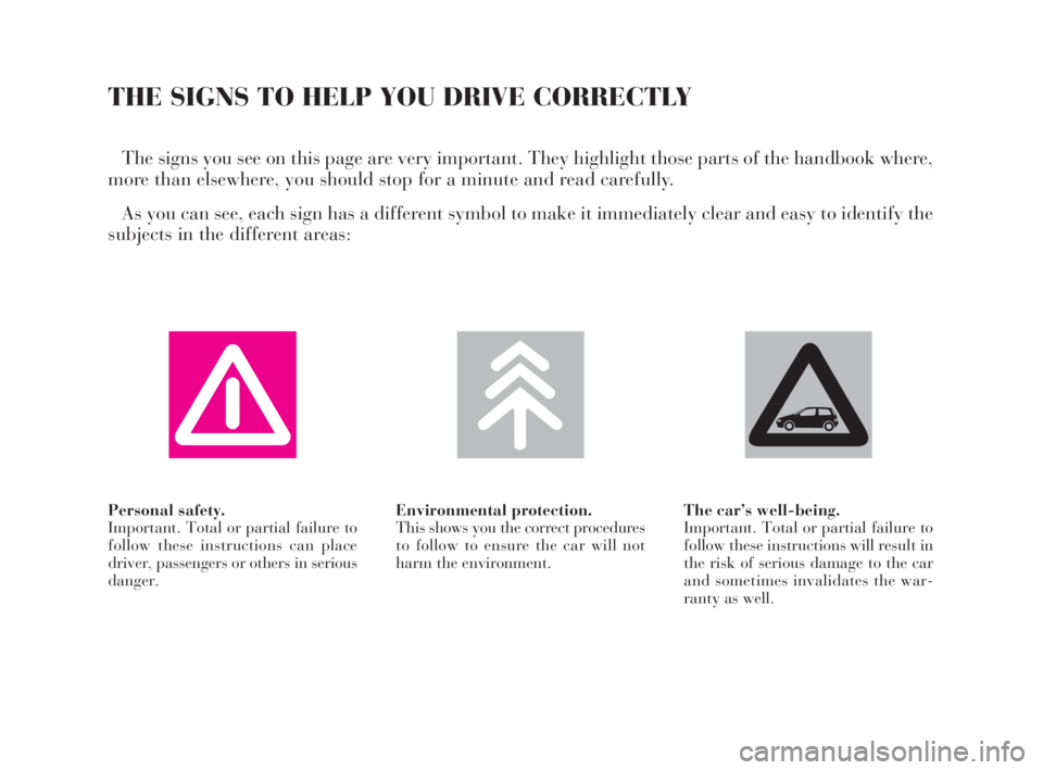
Personal safety.
Important. Total or partial failure to
follow these instructions can place
driver, passengers or others in serious
danger.Environmental protection.
This shows you the correct procedures
to follow to ensure the car will not
harm the environment.The car’s well-being.
Important. Total or partial failure to
follow these instructions will result in
the risk of serious damage to the car
and sometimes invalidates the war-
ranty as well.
THE SIGNS TO HELP YOU DRIVE CORRECTLY
The signs you see on this page are very important. They highlight those parts of the handbook where,
more than elsewhere, you should stop for a minute and read carefully.
As you can see, each sign has a different symbol to make it immediately clear and easy to identify the
subjects in the different areas:
4C001-067 ING 11-03-2008 11:57 Pagina 5
Page 13 of 191
You are recommended to read this chapter sit-
ting comfortably in your new Lancia Y. In this
way you will be able to identify the parts de-
scribed immediate and see for yourself what you
have just read.
In short, you will increase your knowledge of your
Lancia Y with its controls and other devices. Later,
when you start the engine and join the traffic you
will make a host of other pleasant discoveries.
DASHBOARD................................................. 11
THE LANCIA CODE SYSTEM....................... 13
IGNITION SWITCH ........................................ 16
INDIVIDUAL SETTINGS ............................... 17
SEAT BELTS .................................................. 21
TRANSPORTING CHILDREN SAFELY .......... 26
INSTRUMENT PANEL ................................... 29
INSTRUMENTS............................................. 31
WARNING LIGHTS ........................................ 34HEATING AND VENTILATION ..................... 37
CLIMATE CONTROL SYSTEM....................... 40
STEERING COLUMN STALKS ...................... 41
CONTROLS.................................................... 43
INTERIOR EQUIPMENT ................................ 45
SUNROOF...................................................... 48
DOORS........................................................... 49
BOOT ............................................................. 51
BONNET........................................................ 53
SKI AND ROOF RACKS................................. 55
HEADLIGHTS............................................... 55
ABS ................................................................ 56
FRONT AND SIDE AIRBAGS.......................... 58
EOBD SYSTEM............................................... 63
SOUND SYSTEM ........................................... 64
RADIO-NAVIGATION SYSTEM..................... 65
CELLULAR PHONE SETUP........................... 66
FUEL TANK CAP ............................................ 67
10
G
GETTING TO KNOW YOUR CAR
4C001-067 ING 11-03-2008 11:57 Pagina 10
Page 14 of 191
11
G
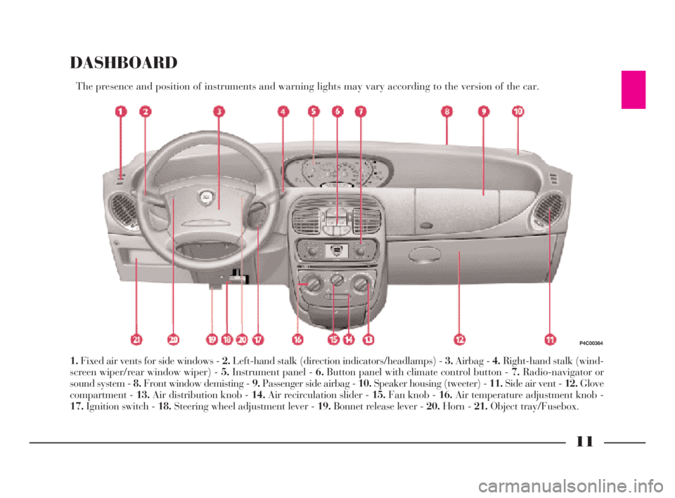
DASHBOARD
The presence and position of instruments and warning lights may vary according to the version of the car.
1.Fixed air vents for side windows - 2.Left-hand stalk (direction indicators/headlamps) - 3.Airbag - 4.Right-hand stalk (wind-
screen wiper/rear window wiper) - 5.Instrument panel - 6.Button panel with climate control button - 7.Radio-navigator or
sound system - 8.Front window demisting - 9.Passenger side airbag - 10.Speaker housing (tweeter) - 11.Side air vent - 12.Glove
compartment - 13.Air distribution knob - 14.Air recirculation slider - 15.Fan knob - 16.Air temperature adjustment knob -
17.Ignition switch - 18.Steering wheel adjustment lever - 19.Bonnet release lever - 20.Horn - 21.Object tray/Fusebox.
P4C00364
4C001-067 ING 11-03-2008 11:57 Pagina 11
Page 15 of 191
12
G
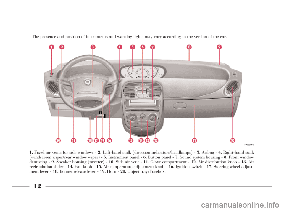
The presence and position of instruments and warning lights may vary according to the version of the car.
1.Fixed air vents for side windows - 2.Left-hand stalk (direction indicators/headlamps) - 3.Airbag - 4.Right-hand stalk
(windscreen wiper/rear window wiper) - 5.Instrument panel - 6.Button panel - 7.Sound system housing - 8.Front window
demisting - 9.Speaker housing (tweeter) - 10.Side air vent - 11.Glove compartment - 12.Air distribution knob - 13.Air
recirculation slider - 14.Fan knob - 15.Air temperature adjustment knob - 16.Ignition switch - 17.Steering wheel adjust-
ment lever - 18.Bonnet release lever - 19.Horn - 20.Object tray/Fusebox.
P4C00365
4C001-067 ING 11-03-2008 11:57 Pagina 12
Page 17 of 191
14
G
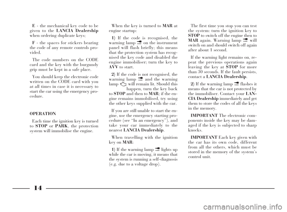
E- the mechanical key code to be
given to the LANCIA Dealership
when ordering duplicate keys;
F- the spaces for stickers bearing
the code of any remote controls pro-
vided.
The code numbers on the CODE
card and the key with the burgundy
grip must be kept in a safe place.
You should keep the electronic code
written on the CODE card with you
at all times in case it is necessary to
start the car using the emergency pro-
cedure.
OPERATION
Each time the ignition key is turned
toSTOPorPARK, the protection
system will immobilise the engine.When the key is turned to MARat
engine startup:
1)If the code is recognised, the
warning lamp ¢on the instrument
panel will flash briefly; this means
that the protection system has recog-
nised the key code and disabled the
engine immobiliser; turn the key to
AVVto start.
2)If the code is not recognised, the
warning lamp ¢and the warning
lamp will remain lit. Should this
happen, turn the key back
toSTOPand then to MAR; if the en-
gine remains immobilised, try using
the other keys supplied with the car.
If you are still unable to start the en-
gine, use the emergency starting pro-
cedure (see “In an emergency”), and
take your car immediately to the
nearestLANCIA Dealership.
When travelling with the ignition
key on MAR:
1)If the warning lamp ¢lights up
while the car is moving, it means that
the system is running a self-diagnosis
(e.g. due to a voltage drop). The first time you stop you can test
the system: turn the ignition key to
STOPto switch off the engine then to
MARagain. Warning lamp ¢will
switch on and should switch off again
after about 1 second.
If the warning light remains on, re-
peat the previous operations again
leaving the key at STOPfor more
than 30 seconds. If the fault persists,
contact a LANCIA Dealership.
2)If the warning lamp ¢flashes it
means that the car is not protected by
the immobiliser. Contact your LAN-
CIA Dealershipimmediately and get
them to store the codes of all the keys
in the memory.
IMPORTANTThe electronic com-
ponents inside the key may be dam-
aged if the key is subjected to sharp
knocks.
IMPORTANTEach key given with
the car has its own code, different
from all the others, which must be
stored in the memory of the system’s
control unit.
4C001-067 ING 11-03-2008 11:57 Pagina 14
Page 19 of 191
IGNITION SWITCH
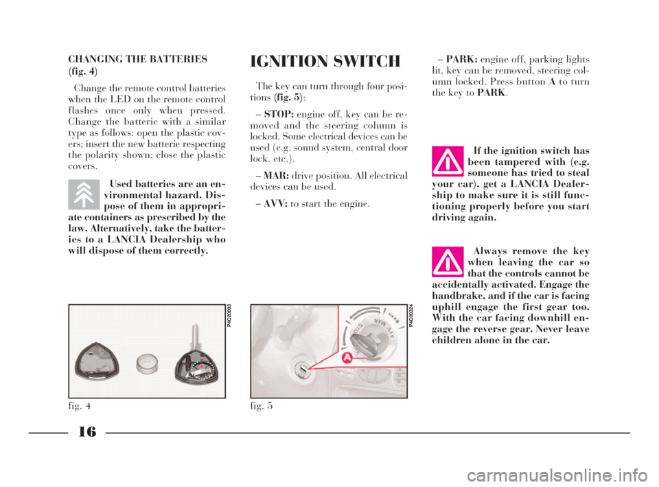
The key can turn through four posi-
tions(fig. 5):
–STOP:engine off, key can be re-
moved and the steering column is
locked. Some electrical devices can be
used (e.g. sound system, central door
lock, etc.).
–MAR:drive position. All electrical
devices can be used.
–AVV:to start the engine.–PARK:engine off, parking lights
lit, key can be removed, steering col-
umn locked. Press button Ato turn
the key to PARK.
fig. 5
P4C00324
If the ignition switch has
been tampered with (e.g.
someone has tried to steal
your car), get a LANCIA Dealer-
ship to make sure it is still func-
tioning properly before you start
driving again.
Always remove the key
when leaving the car so
that the controls cannot be
accidentally activated. Engage the
handbrake, and if the car is facing
uphill engage the first gear too.
With the car facing downhill en-
gage the reverse gear. Never leave
children alone in the car.
16
G
CHANGING THE BATTERIES
(fig. 4)
Change the remote control batteries
when the LED on the remote control
flashes once only when pressed.
Change the batterie with a similar
type as follows: open the plastic cov-
ers; insert the new batterie respecting
the polarity shown; close the plastic
covers.
Used batteries are an en-
vironmental hazard. Dis-
pose of them in appropri-
ate containers as prescribed by the
law. Alternatively, take the batter-
ies to a LANCIA Dealership who
will dispose of them correctly.
fig. 4
P4C20003
4C001-067 ING 11-03-2008 11:57 Pagina 16
Page 20 of 191
17
G
STEERING COLUMN LOCK
To set: remove the ignition key from
theSTOPorPARKposition, and
turn the steering wheel until it locks.
To release: move the steering wheel
slightly as you turn the ignition key to
MAR.
Never remove the ignition
key while the car is mov-
ing. The steering wheel
would automatically lock as soon
as you tried to turn it. This also
applies when the car is being
towed.INDIVIDUAL
SETTINGS
Adjustments must be
made only when the car is
stationary.
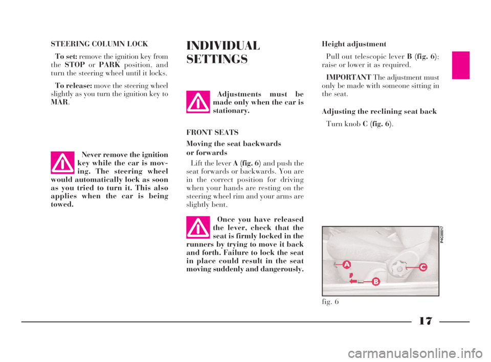
FRONT SEATS
Moving the seat backwards
or forwards
Lift the lever A (fig. 6)and push the
seat forwards or backwards. You are
in the correct position for driving
when your hands are resting on the
steering wheel rim and your arms are
slightly bent.Height adjustment
Pull out telescopic lever B (fig. 6);
raise or lower it as required.
IMPORTANTThe adjustment must
only be made with someone sitting in
the seat.
Adjusting the reclining seat back
Turn knob C (fig. 6).
fig. 6
P4C00017
Once you have released
the lever, check that the
seat is firmly locked in the
runners by trying to move it back
and forth. Failure to lock the seat
in place could result in the seat
moving suddenly and dangerously.
4C001-067 ING 11-03-2008 11:57 Pagina 17
Page 23 of 191

20
G
Electrically-adjustable (fig. 14)
The mirrors can only be adjusted
electrically when the ignition key is at
MAR.
All you need to do is press any of the
four directions on switch Ato perform
this operation.
Use switch Bto select the mirror
(right or left) you want to adjust.
Electrically folding mirrors have an
electrical device for demisting the
mirrors that comes on automatically
when you turn on the rear window
heater.
fig. 14
P4C00023
fig. 15
P4C00317
If the mirror makes it dif-
ficult to get through nar-
row gaps, fold it from po-
sition 1 to position 2 (fig. 15).
When driving the mirrors
should always be in ex-
tended position 1.
The external curved rear
view mirrors slightly alter
the perception of distance.
DOOR MIRRORS
Hand-adjustable (fig. 13)
Turn knob Ainside the car.
fig. 13
P4C00063
4C001-067 ING 11-03-2008 11:57 Pagina 20
Page 30 of 191
27
G
fig. 24
P4C00310
fig. 25
P4C00311
We recommend sitting
children on the rear seat.
This is the most protected
position in the event of a crash.
Never fit child restraint systems in
the front passenger seat in vehicles
with a passenger airbag. The in-
flated airbag could cause even fa-
tal injury, regardless of the sever-
ity of the crash which triggered it
off.
Children can sit in the front pas-
senger seat in cars with passenger
side airbag only if the system has
been deactivated. In this case, al-
ways make sure that the amber in-
strument panel warning light is on
to confirm that the airbag has been
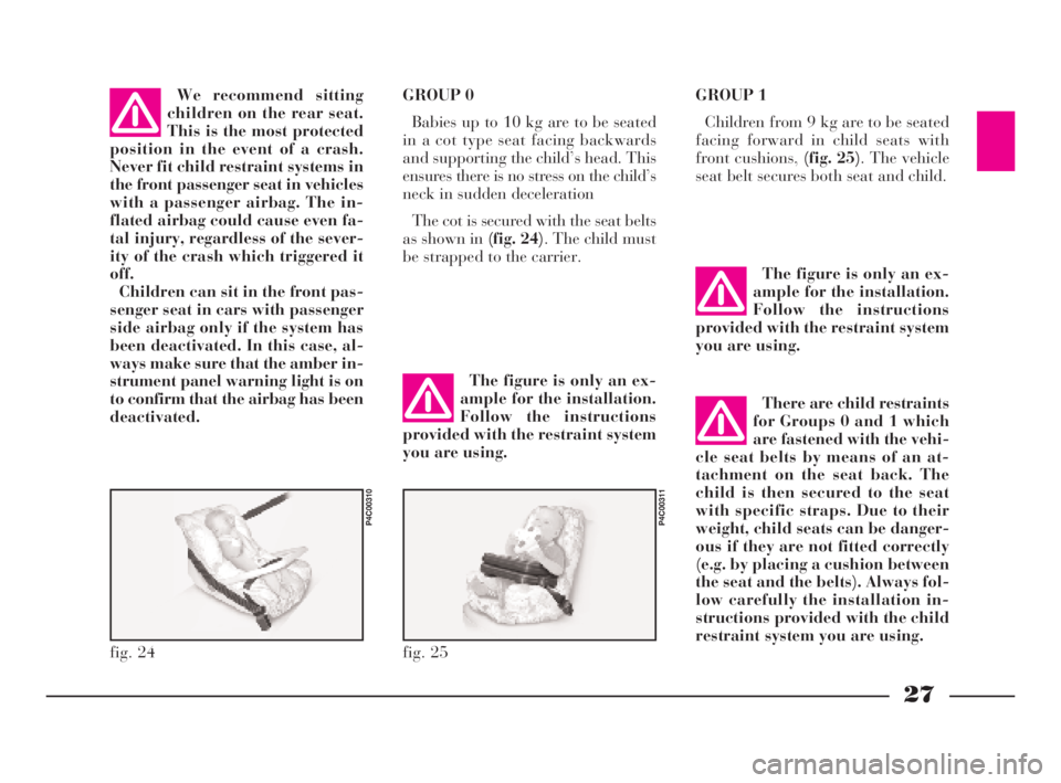
deactivated.GROUP 0
Babies up to 10 kg are to be seated
in a cot type seat facing backwards
and supporting the child’s head. This
ensures there is no stress on the child’s
neck in sudden deceleration
The cot is secured with the seat belts
as shown in (fig. 24). The child must
be strapped to the carrier.GROUP 1
Children from 9 kg are to be seated
facing forward in child seats with
front cushions, (fig. 25). The vehicle
seat belt secures both seat and child.
The figure is only an ex-
ample for the installation.
Follow the instructions
provided with the restraint system
you are using.
The figure is only an ex-
ample for the installation.
Follow the instructions
provided with the restraint system
you are using.
There are child restraints
for Groups 0 and 1 which
are fastened with the vehi-
cle seat belts by means of an at-
tachment on the seat back. The
child is then secured to the seat
with specific straps. Due to their
weight, child seats can be danger-
ous if they are not fitted correctly
(e.g. by placing a cushion between
the seat and the belts). Always fol-
low carefully the installation in-
structions provided with the child
restraint system you are using.
4C001-067 ING 11-03-2008 11:57 Pagina 27
Page 31 of 191
28
G
fig. 26
P4C00313
fig. 27
P4C00314
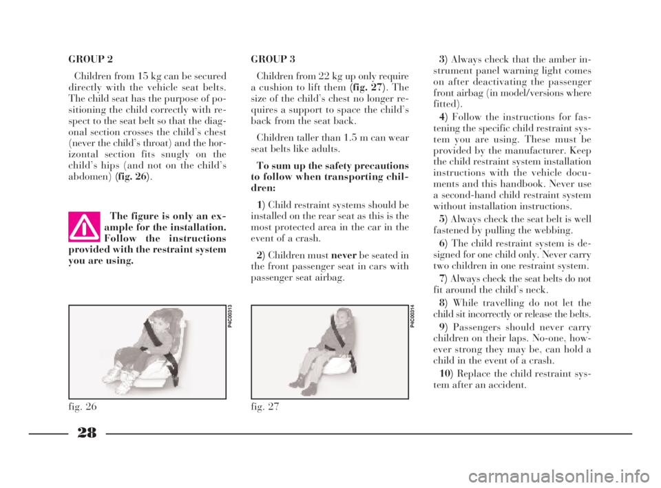
GROUP 2
Children from 15 kg can be secured
directly with the vehicle seat belts.
The child seat has the purpose of po-
sitioning the child correctly with re-
spect to the seat belt so that the diag-
onal section crosses the child’s chest
(never the child’s throat) and the hor-
izontal section fits snugly on the
child’s hips (and not on the child’s
abdomen)(fig. 26).GROUP 3
Children from 22 kg up only require
a cushion to lift them (fig. 27). The
size of the child’s chest no longer re-
quires a support to space the child’s
back from the seat back.
Children taller than 1.5 m can wear
seat belts like adults.
To sum up the safety precautions
to follow when transporting chil-
dren:
1)Child restraint systems should be
installed on the rear seat as this is the
most protected area in the car in the
event of a crash.
2)Children must neverbe seated in
the front passenger seat in cars with
passenger seat airbag.3)Always check that the amber in-
strument panel warning light comes
on after deactivating the passenger
front airbag (in model/versions where
fitted).
4)Follow the instructions for fas-
tening the specific child restraint sys-
tem you are using. These must be
provided by the manufacturer. Keep
the child restraint system installation
instructions with the vehicle docu-
ments and this handbook. Never use
a second-hand child restraint system
without installation instructions.
5)Always check the seat belt is well
fastened by pulling the webbing.
6)The child restraint system is de-
signed for one child only. Never carry
two children in one restraint system.
7)Always check the seat belts do not
fit around the child’s neck.
8)While travelling do not let the
child sit incorrectly or release the belts.
9)Passengers should never carry
children on their laps. No-one, how-
ever strong they may be, can hold a
child in the event of a crash.
10)Replace the child restraint sys-
tem after an accident. The figure is only an ex-
ample for the installation.
Follow the instructions
provided with the restraint system
you are using.
4C001-067 ING 11-03-2008 11:57 Pagina 28