lights Lancia Ypsilon 2003 Owner handbook (in English)
[x] Cancel search | Manufacturer: LANCIA, Model Year: 2003, Model line: Ypsilon, Model: Lancia Ypsilon 2003Pages: 191, PDF Size: 2.45 MB
Page 98 of 191

95
G
Signal that the car is sta-
tionary as per the highway
code: hazard lights, warn-
ing triangle, etc.
Any passengers must get out of
the car, especially if it is heavily
laden, and keep out of the way of
traffic while the wheel is being
changed.
If the ground is sloping or
bumpy, place wedges or other suit-
able material under the wheels to
stop the car from moving.The space-saver spare
wheel is specific to the ve-
hicle; do not use it on other
models and do not use spare
wheels designed for other models
on your car.
If you change the type of wheels
fitted (alloy rims instead of steel
ones), you must also change the se-
curing bolts for others of suitable
dimensions.
The space-saver spare wheel
must only be used in the event of
an emergency, and then only for as
little as possible and at no more
than 80 km/h. Driving will feel dif-
ferent with the space-saver spare
wheel fitted. Avoid sharp braking
and acceleration, sudden swerving
and fast cornering.The space-saver spare wheel has
a life-span of about 3000 km after
which the tyre should be replaced
with another of the same type.
4C090-119 ING 11-03-2008 12:00 Pagina 95
Page 100 of 191

97
G
1. STOP THE CAR
– Stop the car so it is not a danger
for on-coming traffic and in such a
position that the tyre can be changed
in safety. The ground must be flat and
adequately firm. During the night,
chose a lit area, if possible.
– Turn engine off and engage the
handbrake.
– Engage first or reverse gear.
– Signal that the car is stopped ac-
cording to traffic regulations: hazard
lights, warning triangle, etc.
Any passengers must leave the car
and watch out for traffic while the
tyre is being changed.
If the ground is sloping or bumpy,
place wedges or other suitable mate-
rial for stopping the car under the
wheels.2. TAKE OUT THE TOOLS,
JACK AND SPARE WHEEL
(space-saver wheel)
They are in the boot.
– Lift the carpeting.
– Unscrew the fastener A (fig. 2)
and take out the tool holder.
The tool holder contains:
B- vehicle tow ring;
C- jack handle;
D- wheel bolt wrench;
E- screwdriver;F- extension for screwing wheel
bolts and inflation valve cap;
G- jack.
fig. 4
P4C00402
fig. 5
P4C00045
4C090-119 ING 11-03-2008 12:00 Pagina 97
Page 104 of 191

101
fG
C Tubular bulbs
Release these bulbs from rela-
tive contacts to remove them.
D Halogen bulbs
Release the securing spring
from its seat to remove the
bulb.BULB Fig. 9 TYPE POWER
Main beam headlights
Dipped beam headlights
Front side lights
Front direction indicators
Side direction indicators
Rear direction indicators
Foglights
Reverse lights
Rear brake and side lights
Rear side lights
Rear fog lights
Third brake light
Number plate
Ceiling light (1.2 16VM Nblue- LS versions)
Ceiling light:
– with courtesy light
– with map light
BootD H3 12V-55W
D H7 12V-55W
A W5W 12V-5W
B PY21W 12V-21W
A W5W 12V-5W
B PY21W 12V-21W
D H1 12V-55W
B P21W 12V-21W
B R5W 12V-21/5W
B R5W 12V-21W
B P21W 12V-21W
A W5W 12V-5W
C C5W 12V-5W
C – 12V-10W
C – 12V-10W
A – 12V-6W
C C5W 12V-5W
4C090-119 ING 13-03-2008 12:51 Pagina 101
Page 105 of 191

102
fG
FRONT SIDE LIGHTS
To replace the 12V-5W bulb (type
W5W):
1)Remove the cover B (fig.10)by
turning partially in an anti-clockwise
direction.
2)Slide out bulb holder C (fig. 12)
by turning it slightly to make it easier
to release.
3)Remove the bulb.
4)Replace the press-fit bulb and re-
fit the bulb holder and cover.
fig. 12
P4C00025
HEADLIGHTS
To replace the halogen lights (12V-
55W):
1)Remove covers AandB (fig. 10)
by turning them partially in an anti-
clockwise direction.
2)Release the clips C-E (fig. 11)
and remove the burnt-out bulb D
(mainbeam headlight of type H3 with
printed wire already attached) or F
(dippedbeam headlight, type H7).
3)Insert the new bulb, making sure
it is positioned properly.
4)Reattach the securing clips and
close the covers.IF AN EXTERIOR
LIGHT BURNS OUT
fig. 10
P4C00027
fig. 11
P4C00026
Modifications or repairs
to the electrical system
carried out incorrectly and
without bearing the features of the
system in mind can cause mal-
functions with the risk of fire.
4C090-119 ING 13-03-2008 12:51 Pagina 102
Page 107 of 191

REAR LIGHT CLUSTER
1)From inside the car boot, lift the
carpeting and undo screw A (fig. 19)
securing the light cluster.
2)Remove the light cluster B.
3)Replace the burnt-out bulb by
pushing it slightly and turning anti-
clockwise.
Bulbs in (fig. 20):
C - 12V-21W (orange) (type PY21W)
for the direction indicators.
D - 12-21W (type P21W) for the re-
versing lights.
104
fG
3)Remove the bulb holder B
(fig. 16)fromCin the lens.
4)Remove press-fit bulb Dand re-
place it.
5)Refit the bulb holder into Cand
then fit the lens.
FRONT FOGLIGHTS
To replace the halogen bulb 12V-
55W (type H1):
1)Turn the wheels to the right to get
at the left light, and to the left to get
at the right light.
2)Unscrew screw A (fig. 17)in the
cover on the wheelarch.3)Turn cover Bin an anticlockwise
direction.
4)Release clip D (fig. 18)and re-
move bulbC.
5)Release the clip Dand screw
coverBback in.
fig. 16
P4C00383
fig. 17
P4C00152
fig. 18
P4C00406
fig. 19
P4C00038
4C090-119 ING 13-03-2008 12:51 Pagina 104
Page 108 of 191

105
fG
E- 12V-21/5W (type R5W) for the
brake and taillights.
F- 12V-5W (type R5W) for the tail-
lights.
G- 12V-21W (type P21W) for the
rear foglights.
5)Refit the lighting cluster, and
tighten screw A (fig. 19), without
forcing it.THIRD BRAKE LIGHT
To change one or more 12V-5W
(type W5W) bulbs:
1)Unscrew the two screws A (fig. 21)
and remove trim B.
2)Loosen the two screws C (fig. 22),
disconnect the connector Dand sep-
arate the lens from the cover B.
3)Loosen the tab E (fig. 23)and
separate the bulbs from the lens.4)Replace the burnt-out bulb F
(fig. 23).
5)Refit the unit by reversing the
various operations.
fig. 20
P4C00039
fig. 21
P4C00407
fig. 22
P4C00408
fig. 23
P4C00409
4C090-119 ING 13-03-2008 12:51 Pagina 105
Page 109 of 191

106
fG
IF AN INTERIOR
LIGHT BURNS OUTrounding it, by inserting the tip of a
screwdriver between the cover frame
and the second frame as illustrated in
(fig. 25).
CEILING LIGHT
(all other versions)
To replace a bulb:
1)Remove the 2 plastic caps Aand
release cover B (fig. 26).
2)Unscrew the 4 screws securing the
ceiling light unit that can be seen.
3)Press tab A (fig. 27)to open the
bulb holder.
4)Replace the burnt-out bulb.
B- 12V-10W bulb for courtesy light.
C- 12V-6W bulb for map-reading
light. NUMBER PLATE LIGHTS
To replace the 12V-5W (type C5W)
bulb, unscrew the securing screws A
(fig. 24)and remove the lens.
CEILING LIGHT (1.2
16VM Nblue
- LS)
To replace the 12V-10W bulb in the
ceiling lamp, remove the transparent
cover, together with the frame sur-Modifications or repairs
to the electrical system
carried out incorrectly and
without bearing the features of the
system in mind can cause mal-
functions with the risk of fire.
fig. 24
P4C00147
fig. 25
P4C00164
fig. 26
P4C00064
4C090-119 ING 13-03-2008 12:51 Pagina 106
Page 113 of 191

110
fG
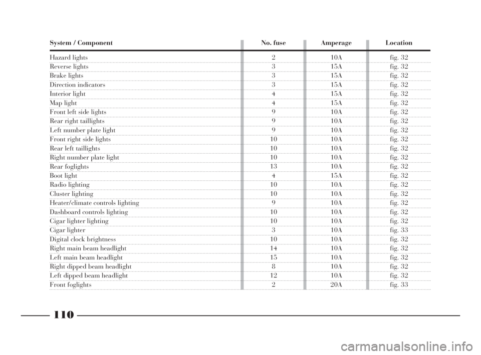
System / Component No. fuse Amperage Location
Hazard lights
Reverse lights
Brake lights
Direction indicators
Interior light
Map light
Front left side lights
Rear right taillights
Left number plate light
Front right side lights
Rear left taillights
Right number plate light
Rear foglights
Boot light
Radio lighting
Cluster lighting
Heater/climate controls lighting
Dashboard controls lighting
Cigar lighter lighting
Cigar lighter
Digital clock brightness
Right main beam headlight
Left main beam headlight
Right dipped beam headlight
Left dipped beam headlight
Front foglights
2 10A fig. 32
3 15A fig. 32
3 15A fig. 32
3 15A fig. 32
4 15A fig. 32
4 15A fig. 32
9 10A fig. 32
9 10A fig. 32
9 10A fig. 32
10 10A fig. 32
10 10A fig. 32
10 10A fig. 32
13 10A fig. 32
4 15A fig. 32
10 10A fig. 32
10 10A fig. 32
9 10A fig. 32
10 10A fig. 32
10 10A fig. 32
3 10A fig. 33
10 10A fig. 32
14 10A fig. 32
15 10A fig. 32
8 10A fig. 32
12 10A fig. 32
2 20A fig. 33
4C090-119 ING 13-03-2008 12:51 Pagina 110
Page 114 of 191

111
fG
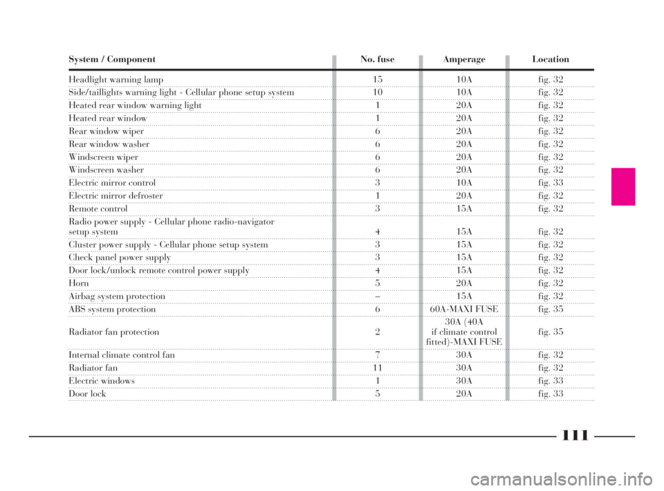
Headlight warning lamp
Side/taillights warning light - Cellular phone setup system
Heated rear window warning light
Heated rear window
Rear window wiper
Rear window washer
Windscreen wiper
Windscreen washer
Electric mirror control
Electric mirror defroster
Remote control
Radio power supply - Cellular phone radio-navigator
setup system
Cluster power supply - Cellular phone setup system
Check panel power supply
Door lock/unlock remote control power supply
Horn
Airbag system protection
ABS system protection
Radiator fan protection
Internal climate control fan
Radiator fan
Electric windows
Door lock System / Component No. fuse Amperage Location
15 10A fig. 32
10 10A fig. 32
1 20A fig. 32
1 20A fig. 32
6 20A fig. 32
6 20A fig. 32
6 20A fig. 32
6 20A fig. 32
3 10A fig. 33
1 20A fig. 32
3 15A fig. 32
4 15A fig. 32
3 15A fig. 32
3 15A fig. 32
4 15A fig. 32
5 20A fig. 32
– 15A fig. 32
6 60A-MAXI FUSE fig. 35
30A (40A
2 if climate control fig. 35
fitted)-MAXI FUSE
7 30A fig. 32
11 30A fig. 32
1 30A fig. 33
5 20A fig. 33
4C090-119 ING 13-03-2008 12:51 Pagina 111
Page 120 of 191

117
fG
While the car is being
towed with the engine off,
remember that the brake
pedal and steering will require
more effort as you no longer have
the benefit of the brake booster
and power steering. Do not use
flexible cables to tow. Avoid jerk-
ing. Whilst towing, ensure that the
coupling to the car does not dam-
age the surrounding components.Do not extract the igni-
tion key during towing;
leave it at MAR, to prevent
the steering lock engaging and,
provided the electrical system is
not damaged, keep the brake lights
and direction indicators working.
When the ignition key is re-
moved, the steering lock will cut in
thus preventing the steering wheel
from being turned.IF AN ACCIDENT
OCCURS
– It is important to keep calm.
– If you are not directly involved,
stop at least ten metres away from the
accident.
– If you are on a motorway do not
obstruct the emergency lane with your
car.
– Turn off the engine and turn on
the hazard lights.
– At night, illuminate the scene of
the accident with your headlights.
– Act carefully, you must not risk
being run over.
– Mark the accident by putting the
red triangle at the regulatory distance
from the car where it can be clearly
seen.
– If the doors are jammed, do not try
to leave the car by breaking the glass
of the windscreen as the glass is strat-
ified. Side windows and the rear win-
dow can be broken more easily.
4C090-119 ING 13-03-2008 12:51 Pagina 117