wiring diagram Lancia Ypsilon 2003 Owner handbook (in English)
[x] Cancel search | Manufacturer: LANCIA, Model Year: 2003, Model line: Ypsilon, Model: Lancia Ypsilon 2003Pages: 191, PDF Size: 2.45 MB
Page 69 of 191

66
G
CELLULAR PHONE
SETUP
If the car has been ordered to in-
clude provision for the fitting of cel-
lular phones, it will have:
– one dual purpose speaker (sound
system and cellular phone) located in
the right-hand door;
– one dual purpose aerial (sound
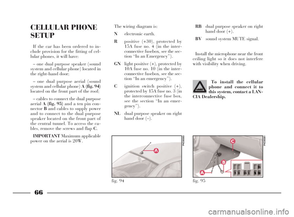
system and cellular phone) A (fig. 94)
located on the front part of the roof;
– cables to connect the dual purpose
aerialA (fig. 95)and a ten pin con-
nectorBand cables to supply power
and to connect to the dual purpose
speaker located on the front part of
the central tunnel. To access the ca-
bles, remove the screws and flap C.
IMPORTANTMaximum applicable
power on the aerial is 20W.The wiring diagram is:
Nelectronic earth.
Rpositive (+30), protected by
15A fuse no. 4 (in the inter-
connective fusebox, see the sec-
tion “In an Emergency”).
GNlight positive (+), protected by
10A fuse no. 10 (in the inter-
connective fusebox, see the sec-
tion “In an emergency”).
Cignition switch positive (+),
protected by 15A fuse no. 3 (in
the interconnective fuse box,
see the section “In an emer-
gency”).
NLdual purpose speaker on right
hand door (–).To install the cellular
phone and connect it to
this system, contact a LAN-
CIA Dealership.
fig. 94
P4C00303
RBdual purpose speaker on right
hand door (+).
BVsound system MUTE signal.
Install the microphone near the front
ceiling light so it does not interfere
with visibility when driving.
fig. 95
P4C00361
4C001-067 ING 11-03-2008 11:57 Pagina 66
Page 172 of 191

169
G
SOUND SYSTEM/RADIO NAVIGATION SYSTEM
SET-UP SYSTEM WIRING
DIAGRAM AND ADDITIONAL
BRANCHES (SOUND SYSTEM)
(fig. 1)
A- Radio aerial;
B- Terminal box;
C- High-amp fuse box;
D- Front left speaker;
E- Left tweeter;
F- Right tweeter;
G- Front right speaker;
H- Radio;
I- Rear right speaker;
L- Rear left speaker;
M- CD CHANGER (where fitted)
wire with respectiving connector,
where you can install a compatible
CD CHANGER if required;
m- +30;
n- Code positive;
o- Radio lights positive.
List of cable colour codes
N=Black - R=Red - AG=Blue/Yellow - AR=Blue/Red - CV=Orange/Green
CN=Orange/Black - BN=White-Black - GN=Yellow-Black - NZ=Black-Purple
RG=Red-Yellow - RN=Red-Black - SN=Red-Black
fig. 1
P4C00388
4C168-176 ING 11-03-2008 12:03 Pagina 169
Page 173 of 191

170
G
List of cable colour codes
G=Yellow - N=Black - R=Red - AG=Blue/Yellow - AR=Blue/Red - BR=White/Red -
CV=Orange/Green - CN=Orange/Black - BN=White-Black - GN=Yellow-Black -
NZ=Black-PurpleRG=Red-Yellow - RN=Red-Black - SN=Red-Black
SET-UP SYSTEM WIRING
DIAGRAM AND ADDITIONAL
BRANCHES (RADIO
NAVIGATION SYSTEM) (fig. 2)
A- Radio aerial;
B- Terminal box;
C- High-amp fuse box;
D- Front left speaker;
E- Left tweeter;
F- Right tweeter;
G- Front right speaker;
H- Radio-navigator;
I- Rear right speaker;
L- Rear left speaker;
M- Vehicle speed signal;
N- GPS aerial;
O- Reversing signal;
P- CD CHANGER wire with re-
spectiving connector, where you can
install a compatible CD CHANGER if
required;
m- +30;
n- +15;
o- Radio lights positive.
fig. 2
P4C00423
4C168-176 ING 11-03-2008 12:03 Pagina 170