Lancia Ypsilon 2012 Owner handbook (in English)
Ypsilon 2012
Lancia
Lancia
https://www.carmanualsonline.info/img/41/31387/w960_31387-0.png
Lancia Ypsilon 2012 Owner handbook (in English)
Trending: headlamp, glove box, clock setting, check transmission fluid, brake light, tires, light
Page 191 of 307

REPLACING FUSESGENERAL INFORMATION
Fuses protect the electrical system: they intervene
(blow) in the event of a fault or improper
intervention on the system.
When a device does not work, check the condition
of its protective fuse: the conductor element A
fig. 151 must be intact. If it is not, replace the
blown fuse with another with the same amperage
(same colour).
B = intact fuse;
C = fuse with damaged filament.
To replace a fuse, use the tweeters D hooked to the
fuse box lid on the left-hand side of the
dashboard.
Refer to the tables on the following pages to
identify the protective fuse.
WARNING
If a fuse blows again, contact a
Lancia Dealership.
WARNING
Never replace a fuse with metal wires
or anything else.
WARNING
Never replace a fuse with another
with a higher amp rating; DANGER
OF FIRE.
WARNING
If a general protective fuse (MEGA-
FUSE, MIDI-FUSE, MAXI-FUSE)
blows contact a Lancia Dealership.
WARNING
Before replacing a fuse, make sure
that the ignition key has been
removed and that all the other services are
switched off and/or disengaged.
fig. 151
L0F0005
189GETTING TO KNOW
YOUR CAR
SAFETY
STARTING AND
DRIVING
WARNING LIGHTS
AND MESSAGESIN AN EMERGENCYSERVICING AND
MAINTENANCE
TECHNICAL
SPECIFICATIONS
INDEX
Page 192 of 307
WARNING
If a general protective fuse for safety
systems (airbag system, braking
system), power unit systems (engine system,
transmission system) or steering system
intervenes, contact a Lancia Dealership.
FUSE LOCATION
Engine compartment fuse box
This is located next to the battery: to access fuses
fig. 154 proceed as follows:
❒move the cover A fig. 152 aside;
❒undo screw A fig. 153, release tabs B and
remove cover C by pulling upwards.The number identifying the electrical component
corresponding to each fuse is shown on the cover.
After replacing the fuse, make sure that you
have closed cover C correctly on the fuse box.
If you need to wash the engine
compartment, take care not to directly
hit the fuse box and the window wiper
motors with the water jet.
fig. 152
L0F0170
fig. 153
L0F0094
190
GETTING TO KNOW
YOUR CAR
SAFETY
STARTING AND
DRIVING
WARNING LIGHTS
AND MESSAGESIN AN EMERGENCYSERVICING AND
MAINTENANCE
TECHNICAL
SPECIFICATIONS
INDEX
Page 193 of 307
.
fig. 154
L0F0210
191GETTING TO KNOW
YOUR CAR
SAFETY
STARTING AND
DRIVING
WARNING LIGHTS
AND MESSAGESIN AN EMERGENCYSERVICING AND
MAINTENANCE
TECHNICAL
SPECIFICATIONS
INDEX
Page 194 of 307
Dashboard fuse box
To access the fuses, pull the lower part of flap B
fig. 155 with one hand while pushing with the
other hand on part A. The fuses are located in the
fuse box shown in fig. 156.
fig. 155
L0F0171
192
GETTING TO KNOW
YOUR CAR
SAFETY
STARTING AND
DRIVING
WARNING LIGHTS
AND MESSAGESIN AN EMERGENCYSERVICING AND
MAINTENANCE
TECHNICAL
SPECIFICATIONS
INDEX
Page 195 of 307
.
fig. 156
L0F0244
193GETTING TO KNOW
YOUR CAR
SAFETY
STARTING AND
DRIVING
WARNING LIGHTS
AND MESSAGESIN AN EMERGENCYSERVICING AND
MAINTENANCE
TECHNICAL
SPECIFICATIONS
INDEX
Page 196 of 307
Luggage compartment fuse box
The fuse box is located on the left side of the
luggage compartment, underneath the side cover
A fig. 157.
The fuses are located in the fuse box shown in fig.
158.
fig. 157
L0F0128
fig. 158
L0F0212
194
GETTING TO KNOW
YOUR CAR
SAFETY
STARTING AND
DRIVING
WARNING LIGHTS
AND MESSAGESIN AN EMERGENCYSERVICING AND
MAINTENANCE
TECHNICAL
SPECIFICATIONS
INDEX
Page 197 of 307
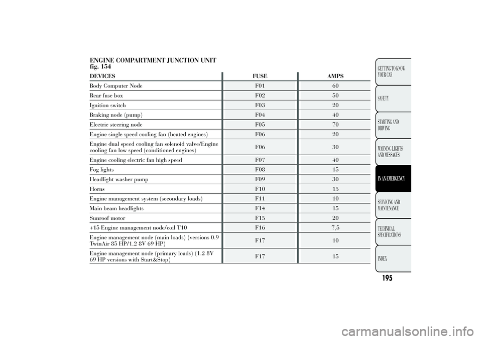
ENGINE COMPARTMENT JUNCTION UNIT fig. 154
195GETTING TO KNOW YOUR CAR SAFETYSTARTING AND DRIVING WARNING LIGHTS AND MESSAGESIN AN EMERGENCYSERVICING ANDMAINTENANCE TECHNICAL SPECIFICATIONS INDEX DEVICES FUSE AMPS Body Computer Node F01 60Rear fuse box F02 50Ignition switch F03 20Braking node (pump) F04 40Electric steering node F05 70Engine single speed cooling fan (heated engines) F06 20Engine dual speed cooling fan solenoid valve/Engine cooling fan low speed (conditioned engines)
F06 30
Engine cooling electric fan high speed F07 40 Fog lights F08 15Headlight washer pump F09 30Horns F10 15Engine management system (secondary loads) F11 10Main beam headlights F14 15Sunroof motor F15 20+15 Engine management node/coil T10 F16 7,5Engine management node (main loads) (versions 0.9 TwinAir 85 HP/1.2 8V 69 HP)
F17 10
Engine management node (primary loads) (1.2 8V 69 HP versions with Start&Stop)
F17 15
Page 198 of 307

196
GETTING TO KNOW
YOUR CAR SAFETY
STARTING AND
DRIVING
WARNING LIGHTS AND MESSAGESIN AN EMERGENCYSERVICING AND MAINTENANCE TECHNICAL
SPECIFICATIONS
INDEX
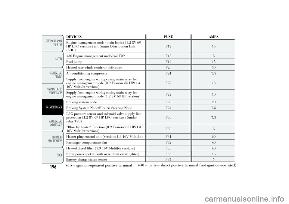
DEVICES FUSE AMPS Engine management node (main loads) (1.2 8V 69 HP LPG versions) and Smart Distribution Unit(SDU)
F17 15
+30 Engine management node/coil T09 F18 5 Fuel pump F19 15Heated rear window/mirror defrosters F20 30Air conditioning compressor F21 7,5Supply from engine wiring casing main relay for engine management node (0.9 TwinAir 85 HP/1.316V MultiJet versions)
F22 15
Supply from engine wiring casing main relay for engine management node (1.2 8V 69 HP versions)
F22 10
Braking system node F23 20 Braking System Node/Electric Steering Node F24 7,5LPG pressure sensor and solenoid valve supply line protection (1.2 8V 69 HP LPG versions) (underrelay T20)
F30 7,5
"Blow by heater" function (0.9 TwinAir 85 HP/1.3 16V MultiJet versions)
F30 5
Heater plug control unit (versions 1.3 16V MultiJet) F81 60 Passenger compartment fan F82 40Heated diesel filter (1.3 16V MultiJet versions) F83 40Front power socket (with or without cigar lighter) F85 15
Battery charge status sensor F87 5+15 = ignition-operated positive terminal +30 = battery direct positive terminal (not ignition-operated)
Page 199 of 307
INSTRUMENT PANEL FUSE BOX
fig. 156DEVICES FUSE AMPS
Free F12 -
+15 headlight alignment corrector F13 5
+15 ignition-operated control with inhibition during
engine startingF31 5
Free F32 -
+30 F36 10
+15 switch on brake pedal (NO) F37 7,5
Door central locking F38 20
Two-way windscreen washer pump F43 20
Front electric window (driver side) F47 20
Front electric window (passenger side) F48 20
+15 F49 7,5
+15 F50 7,5
+15 F51 5
+30 F53 7,5+15 = ignition-operated positive terminal
+30 = battery direct positive terminal (notignition-operated)
197GETTING TO KNOW
YOUR CAR
SAFETY
STARTING AND
DRIVING
WARNING LIGHTS
AND MESSAGESIN AN EMERGENCYSERVICING AND
MAINTENANCE
TECHNICAL
SPECIFICATIONS
INDEX
Page 200 of 307
LUGGAGE COMPARTMENT JUNCTION UNIT
fig. 158DEVICES FUSE AMPS
BOSE HI-FI system F60 20
Free F61 -
Heated seats F62 15
Rear right electric window F63 20
Rear left electric window F64 20
Alarm setup supply F65 7,5
198
GETTING TO KNOW
YOUR CAR
SAFETY
STARTING AND
DRIVING
WARNING LIGHTS
AND MESSAGESIN AN EMERGENCYSERVICING AND
MAINTENANCE
TECHNICAL
SPECIFICATIONS
INDEX
Trending: coolant temperature, instrument panel, tyre pressure, towing capacity, height adjustment, catalytic converter, fold seats


