wheel Lancia Ypsilon 2012 Owner handbook (in English)
[x] Cancel search | Manufacturer: LANCIA, Model Year: 2012, Model line: Ypsilon, Model: Lancia Ypsilon 2012Pages: 307, PDF Size: 13.3 MB
Page 164 of 307

“DUALDRIVE” ELECTRIC POWER
STEERING FAILURE (red)
This warning light switches on when the ignition
key is turned to MAR, but it should switch off
after a few seconds.
If the warning light (or, on some versions, a
message and a symbol on the display) remains on,
you may not have steering assistance and the
effort required to operate the steering wheel could
be notably increased; steering is, however,
possible. In this case, contact a Lancia Dealership.
IMPORTANT In some circumstances, factors
independent of the electric power steering could
cause the warning light on the instrument panel to
switch on. In this case, stop the car immediately,
switch off the engine for about 20 seconds and
then restart the engine. If the warning light (or, on
some versions, a message and a symbol on the
display) remains on constantly, contact a Lancia
Dealership.
IMPORTANT After the battery is disconnected,
the steering must be initialised. The warning light
switches on to indicate this. To carry out this
procedure, simply turn the steering wheel all the
way from one end to the other or drive in a
straight line for about a hundred metres.
CRUISE CONTROL (green)
(for versions/markets, where provided)
This warning light switches on when the ignition
key is turned to MAR, but it should switch off
after a few seconds, if the Cruise Control is
deactivated.
The warning light switches on when the Cruise
Control ring nut is turned to the ON position (see
the “Cruise Control” paragraph in the "Knowing
your car" section). On some versions the display
shows the dedicated message.DPF (PARTICULATE FILTER) BEING
CLEANED
(only Diesel versions with DPF) (amber)
Turning the key to the MAR-ON position
illuminates the warning light, but it should switch
off after a few seconds.
The warning light (together with a message and a
symbol on the display on some versions) switches
on constantly to notify the driver that the DPF
system needs to eliminate captured pollutants
(particulate) through the regeneration process.
162
GETTING TO KNOW
YOUR CAR
SAFETY
STARTING AND
DRIVINGWARNING LIGHTS
AND MESSAGESIN AN EMERGENCY
SERVICING AND
MAINTENANCE
TECHNICAL
SPECIFICATIONS
INDEX
Page 171 of 307
Never use a fast battery-charger to start
the engine as this could damage the
electronic systems of your car,
particularly the ignition and fuel supply
control units.
WARNING
This procedure must be performed by
expert personnel because incorrect
actions could cause electrical discharge of
considerable intensity. Furthermore, battery
fluid is poisonous and corrosive: avoid
contact with skin and eyes. Keep naked
flames and lighted cigarettes away from the
battery and do not cause sparks.
BUMP STARTING
Never jump start the engine by pushing, towing or
coasting downhill.
IMPORTANT Remember that the brake servo and
electrical power steering system are not active
until the engine is started. A much greater effort
will therefore be required to use the brake pedal or
turn the steering wheel.
REPLACING A WHEELGENERAL INSTRUCTIONS
The car is equipped with the “Fix&Go Automatic
Kit”: see the paragraph “Fix&Go Automatic
Kit” for how to use this device.
As an alternative to the “Fix&Go Automatic Kit”
the car may be equipped with a space-saver
wheel: see the instructions on the following pages
for changing the tyre.
WARNING
The space-saver wheel (for versions/
markets where provided) is specific
to your car, do not use it on other models, or
use the space-saver wheel of other models
on your car. The space-saver wheel must
only be used in case of emergency. It must
only be used for the distance necessary
to reach a service point and the car speed
must not exceed 80 km/h. The space-saver
wheel has an orange sticker that summarises
the main cautions for use and limitations.
Never remove or cover the label. The
following information is provided in four
languages on the label: "Important! For
temporary use only! 80 km/h max! Replace
with a standard tyre as soon as possible.
Never cover this indication." Never apply a
hub cap on a space-saver wheel.
169GETTING TO KNOW
YOUR CAR
SAFETY
STARTING AND
DRIVING
WARNING LIGHTS
AND MESSAGESIN AN EMERGENCYSERVICING AND
MAINTENANCE
TECHNICAL
SPECIFICATIONS
INDEX
Page 172 of 307
WARNING
If you change the type of wheel (alloy
rims instead of steel rims and vice
versa) you will have to change the entire set
of fastening bolts with another set of suitably
sized bolts.
WARNING
Alert other drivers that the car is
stationary in compliance with local
regulations: hazard warning lights, warning
triangle, etc. Any passengers on board
should leave the car, especially if it is
heavily laden. Passengers should stay away
from on-coming traffic while the wheel is
being changed. On hills or uneven roads, use
chocks or appropriate objects to block the
wheels of the car.
WARNING
The car's driving characteristics will
be modified with the space-saver
wheel fitted. Avoid sudden starting or
stopping, sharp or fast turns. The total life of
a space-saver wheel is approximately 3000
km, after which it must be replaced by
another wheel of the same type. Never install
a standard tyre on a rim that is designed
for use with a space-saver wheel. Have the
tyre repaired and refitted as soon as
possible. Using two or more space-saver
wheels at the same time is forbidden. Do not
grease the threads of bolts before fitting
them: they might slip out.
170
GETTING TO KNOW
YOUR CAR
SAFETY
STARTING AND
DRIVING
WARNING LIGHTS
AND MESSAGESIN AN EMERGENCYSERVICING AND
MAINTENANCE
TECHNICAL
SPECIFICATIONS
INDEX
Page 173 of 307
WARNING
The jack provided is only intended to
be used for replacing tyres on the
car with which it is supplied, or on
same-model vehicles. Never use the jack for
other purposes, such as lifting other car
models. Never use it for repair operations
under the car. Incorrectly positioning the
jack may cause the car to fall. Do not use the
jack for loads higher than the one shown
on its label. Never install snow chains on the
space-saver wheel; if a front tyre (driving
wheel) is punctured and you need to use
snow chains, use a standard wheel from the
rear axle and install the space-saver wheel
on the rear axle. In this way, with two
normal drive wheels, it is possible to use
snow chains.
WARNING
Fit the wheel cap correctly to prevent
it from coming free in motion. Never
tamper with the inflating valve. Never
introduce tools of any kind between rim and
tyre. Check tyre and space-saver wheel
pressures regularly, referring to the values
shown in the "Technical specifications"
section.JACK
Important notes:
❒the jack weight is 1,76 kg;
❒the jack requires no adjustment;
❒the jack cannot be repaired and in the event of a
fault it must be replaced by another original
one;
❒no tool other than its cranking device may be
fitted on the jack.
To change a wheel proceed as follows:
❒Stop the car in a position that is not dangerous
for oncoming traffic where you can change the
wheel safely. The ground must be flat and
sufficiently compact;
❒switch off the engine, pull up the handbrake
and engage the 1
stgear or the reverse gear.
Wear the reflective safety jacket (compulsory by
law in certain countries) before getting out of
the car;
❒open the luggage compartment, pull tab A fig.
115 and lift up the mat;
❒using the wrench A fig. 116 located in the tool
box, loosen the locking device, take the tool
box B and place it close to the wheel to be
replaced. Then take the space-saver wheel C;
❒take the wrench A fig. 117 and loosen the fixing
bolts by about one turn. For versions with alloy
rims, shake the car to facilitate detachment of
the rim from the wheel hub.
171GETTING TO KNOW
YOUR CAR
SAFETY
STARTING AND
DRIVING
WARNING LIGHTS
AND MESSAGESIN AN EMERGENCYSERVICING AND
MAINTENANCE
TECHNICAL
SPECIFICATIONS
INDEX
Page 174 of 307
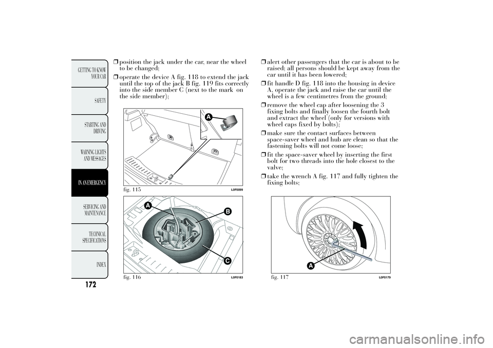
❒position the jack under the car, near the wheel
to be changed;
❒operate the device A fig. 118 to extend the jack
until the top of the jack B fig. 119 fits correctly
into the side member C (next to the mark on
the side member);❒alert other passengers that the car is about to be
raised; all persons should be kept away from the
car until it has been lowered;
❒fit handle D fig. 118 into the housing in device
A, operate the jack and raise the car until the
wheel is a few centimetres from the ground;
❒remove the wheel cap after loosening the 3
fixing bolts and finally loosen the fourth bolt
and extract the wheel (only for versions with
wheel caps fixed by bolts);
❒make sure the contact surfaces between
space-saver wheel and hub are clean so that the
fastening bolts will not come loose;
❒fit the space-saver wheel by inserting the first
bolt for two threads into the hole closest to the
valve;
❒take the wrench A fig. 117 and fully tighten the
fixing bolts;
fig. 115
L0F0099
fig. 116
L0F0183
fig. 117
L0F0179
172
GETTING TO KNOW
YOUR CAR
SAFETY
STARTING AND
DRIVING
WARNING LIGHTS
AND MESSAGESIN AN EMERGENCYSERVICING AND
MAINTENANCE
TECHNICAL
SPECIFICATIONS
INDEX
Page 175 of 307
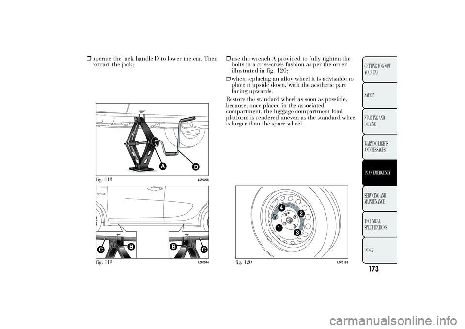
❒operate the jack handle D to lower the car. Then
extract the jack;❒use the wrench A provided to fully tighten the
bolts in a criss-cross fashion as per the order
illustrated in fig. 120;
❒when replacing an alloy wheel it is advisable to
place it upside down, with the aesthetic part
facing upwards.
Restore the standard wheel as soon as possible,
because, once placed in the associated
compartment, the luggage compartment load
platform is rendered uneven as the standard wheel
is larger than the spare wheel.
fig. 118
L0F0025
fig. 119
L0F0024
fig. 120
L0F0182
173GETTING TO KNOW
YOUR CAR
SAFETY
STARTING AND
DRIVING
WARNING LIGHTS
AND MESSAGESIN AN EMERGENCYSERVICING AND
MAINTENANCE
TECHNICAL
SPECIFICATIONS
INDEX
Page 176 of 307
REFITTING THE STANDARD WHEEL
Following the procedure described previously,
raise the car and remove the space-saver wheel.
Versions with steel rims
Proceed as follows:
❒make sure the contact surfaces between
standard wheel and hub are clean so that the
fastening bolts will not come loose;
❒fit the standard wheel inserting the 4 bolts into
the holes;
❒using the wrench provided, tighten the fastening
bolts; ❒press-fit the hub cap, aligning the special
splining (on the cap) with the inflation valve;
❒lower the car and remove the jack;
❒using the wrench provided, fully tighten the
bolts in the sequence shown previously.Versions with alloy wheels
❒insert the wheel on the hub and using the
wrench provided tighten the bolts;
❒lower the car and remove the jack;
❒using the wrench provided, fully tighten the
bolts in the sequence shown ;
❒reinstall the pressure-fitted hub cap, making
sure that the reference hole on the wheel is
aligned with the reference hole on the cap.
IMPORTANT If it is not fitted properly, the hub
cap may detach itself when the car is running.
After tyre replacement
❒stow the space-saver wheel in the compartment
provided in the boot;
❒insert the jack and the other tools in the
container;
❒arrange the container and tools on the
space-saver wheel;
❒correctly reposition the boot stiff cover.
174
GETTING TO KNOW
YOUR CAR
SAFETY
STARTING AND
DRIVING
WARNING LIGHTS
AND MESSAGESIN AN EMERGENCYSERVICING AND
MAINTENANCE
TECHNICAL
SPECIFICATIONS
INDEX
Page 178 of 307
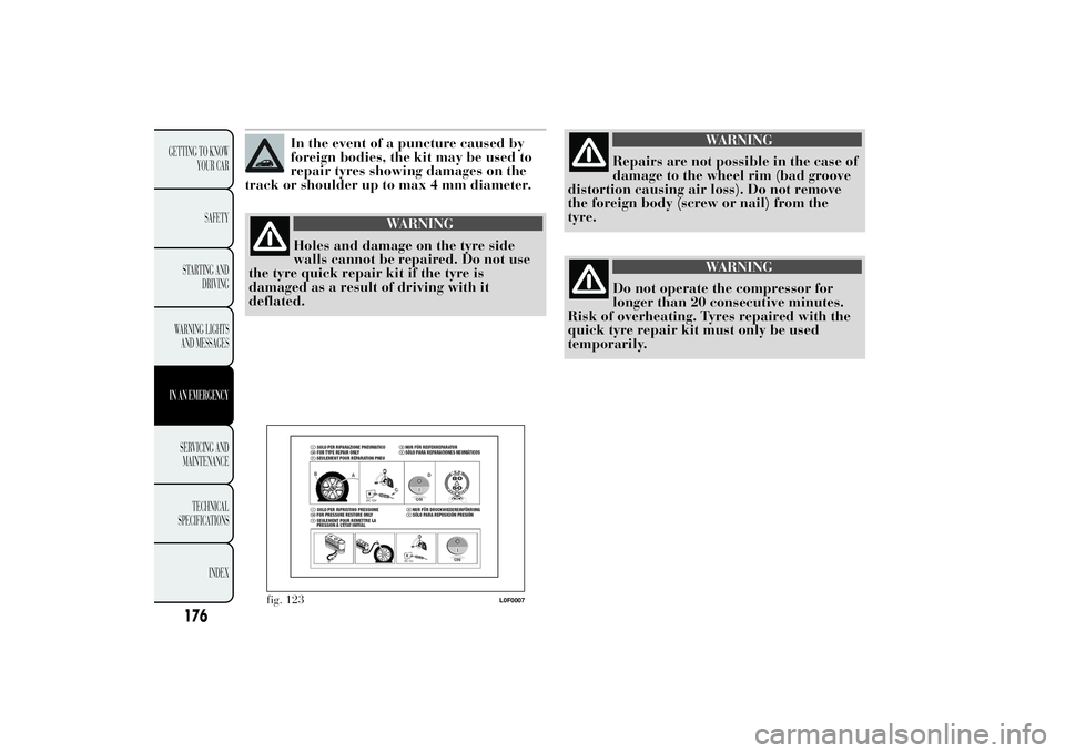
In the event of a puncture caused by
foreign bodies, the kit may be used to
repair tyres showing damages on the
track or shoulder up to max 4 mm diameter.
WARNING
Holes and damage on the tyre side
walls cannot be repaired. Do not use
the tyre quick repair kit if the tyre is
damaged as a result of driving with it
deflated.
WARNING
Repairs are not possible in the case of
damage to the wheel rim (bad groove
distortion causing air loss). Do not remove
the foreign body (screw or nail) from the
tyre.
WARNING
Do not operate the compressor for
longer than 20 consecutive minutes.
Risk of overheating. Tyres repaired with the
quick tyre repair kit must only be used
temporarily.
fig. 123
L0F0007
176
GETTING TO KNOW
YOUR CAR
SAFETY
STARTING AND
DRIVING
WARNING LIGHTS
AND MESSAGESIN AN EMERGENCYSERVICING AND
MAINTENANCE
TECHNICAL
SPECIFICATIONS
INDEX
Page 184 of 307

❒adjust the lens A fig. 134 to compress in the
internal catch B, then pull the unit outwards;
❒turn the bulb holder C anticlockwise, extract the
bulb and replace it;❒refit the bulb holder C in the lens and turn it
clockwise;
❒refit the unit making sure that the internal catch
B clips into position.
FOG LIGHTS
(for versions/markets, where provided)
Replace the bulb as follows:
❒steer the wheel completely;
❒adjust the tabs A fig. 135 and remove the flap
B;
❒adjust the catch C fig. 136 and disconnect the
electrical connector D;
❒remove the cover E by turning it clockwise (see
the word OFF and the arrow on the cover);
❒release the catches F fig. 137 removing them
outwards;
fig. 133
L0F0071
fig. 134
L0F0209
fig. 135
L0F0205
182
GETTING TO KNOW
YOUR CAR
SAFETY
STARTING AND
DRIVING
WARNING LIGHTS
AND MESSAGESIN AN EMERGENCYSERVICING AND
MAINTENANCE
TECHNICAL
SPECIFICATIONS
INDEX
Page 204 of 307

WARNING
Before towing, turn the ignition key to
MAR and then to STOP without
removing it. The steering column will
automatically lock when the key is removed
and the wheels cannot be steered.
WARNING
Before tightening the hook clean the
threaded housing thoroughly. Make
sure that the hook is fully fastened in the
housing before towing the car.
WARNING
Whilst towing, remember that as the
assistance of the brake servo and
the electric power assisted steering is not
available, greater force needs to be exerted
on the brake pedal and more effort is
required on the steering wheel. Do not use
flexible cables when towing and avoid jerky
movements. During towing, make sure that
the trailer hitch does not damage any
components it is touching. When towing the
car, it is compulsory to respect specific
highway code regulations relating to the tow
hook and procedures for towing on the
road. Do not start the engine while towing
the car.
fig. 161
L0F0022
202
GETTING TO KNOW
YOUR CAR
SAFETY
STARTING AND
DRIVING
WARNING LIGHTS
AND MESSAGESIN AN EMERGENCYSERVICING AND
MAINTENANCE
TECHNICAL
SPECIFICATIONS
INDEX