Lancia Ypsilon 2016 Owner handbook (in English)
Manufacturer: LANCIA, Model Year: 2016, Model line: Ypsilon, Model: Lancia Ypsilon 2016Pages: 200, PDF Size: 4.53 MB
Page 11 of 200
THE KEYS
1)1)1)
KEY WITHOUT REMOTE
CONTROL
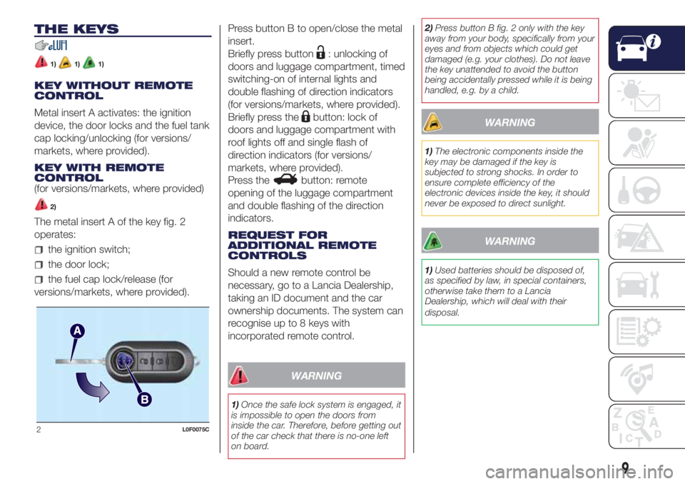
Metal insert A activates: the ignition
device, the door locks and the fuel tank
cap locking/unlocking (for versions/
markets, where provided).
KEY WITH REMOTE
CONTROL
(for versions/markets, where provided)
2)
The metal insert A of the key fig. 2
operates:
the ignition switch;
the door lock;
the fuel cap lock/release (for
versions/markets, where provided).Press button B to open/close the metal
insert.
Briefly press button
: unlocking of
doors and luggage compartment, timed
switching-on of internal lights and
double flashing of direction indicators
(for versions/markets, where provided).
Briefly press the
button: lock of
doors and luggage compartment with
roof lights off and single flash of
direction indicators (for versions/
markets, where provided).
Press the
button: remote
opening of the luggage compartment
and double flashing of the direction
indicators.
REQUEST FOR
ADDITIONAL REMOTE
CONTROLS
Should a new remote control be
necessary, go to a Lancia Dealership,
taking an ID document and the car
ownership documents. The system can
recognise up to 8 keys with
incorporated remote control.
WARNING
1)Once the safe lock system is engaged, it
is impossible to open the doors from
inside the car. Therefore, before getting out
of the car check that there is no-one left
on board.2)Press button B fig. 2 only with the key
away from your body, specifically from your
eyes and from objects which could get
damaged (e.g. your clothes). Do not leave
the key unattended to avoid the button
being accidentally pressed while it is being
handled, e.g. by a child.
WARNING
1)The electronic components inside the
key may be damaged if the key is
subjected to strong shocks. In order to
ensure complete efficiency of the
electronic devices inside the key, it should
never be exposed to direct sunlight.
WARNING
1)Used batteries should be disposed of,
as specified by law, in special containers,
otherwise take them to a Lancia
Dealership, which will deal with their
disposal.
2L0F0075C
9
Page 12 of 200
IGNITION DEVICE
3) 4)
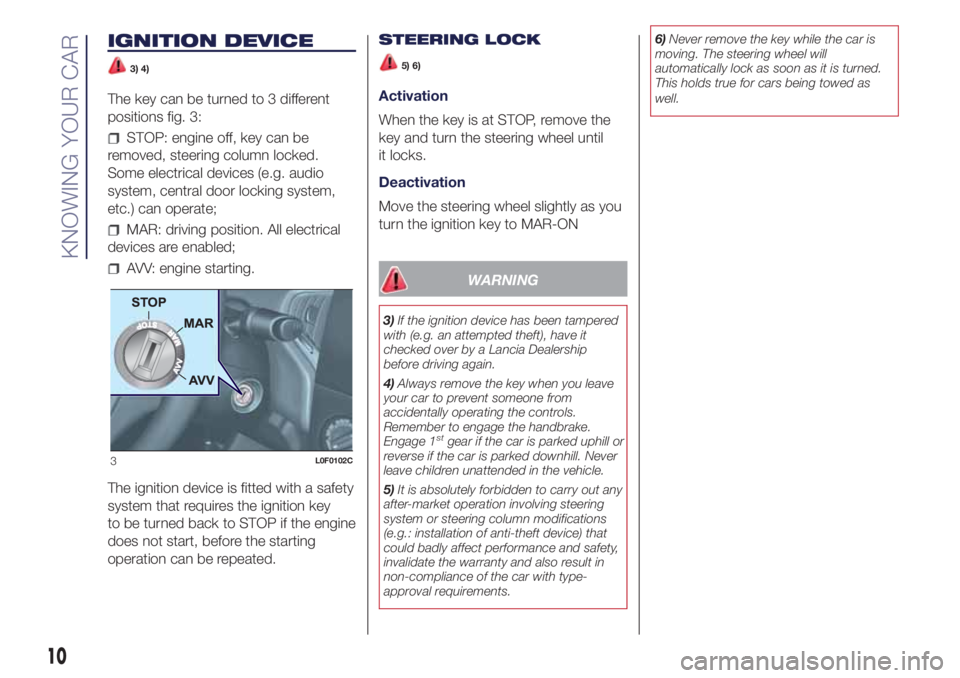
The key can be turned to 3 different
positions fig. 3:
STOP: engine off, key can be
removed, steering column locked.
Some electrical devices (e.g. audio
system, central door locking system,
etc.) can operate;
MAR: driving position. All electrical
devices are enabled;
AVV: engine starting.
The ignition device is fitted with a safety
system that requires the ignition key
to be turned back to STOP if the engine
does not start, before the starting
operation can be repeated.STEERING LOCK
5) 6)
Activation
When the key is at STOP, remove the
key and turn the steering wheel until
it locks.
Deactivation
Move the steering wheel slightly as you
turn the ignition key to MAR-ON
WARNING
3)If the ignition device has been tampered
with (e.g. an attempted theft), have it
checked over by a Lancia Dealership
before driving again.
4)Always remove the key when you leave
your car to prevent someone from
accidentally operating the controls.
Remember to engage the handbrake.
Engage 1
stgear if the car is parked uphill or
reverse if the car is parked downhill. Never
leave children unattended in the vehicle.
5)It is absolutely forbidden to carry out any
after-market operation involving steering
system or steering column modifications
(e.g.: installation of anti-theft device) that
could badly affect performance and safety,
invalidate the warranty and also result in
non-compliance of the car with type-
approval requirements.6)Never remove the key while the car is
moving. The steering wheel will
automatically lock as soon as it is turned.
This holds true for cars being towed as
well.
3L0F0102C
10
KNOWING YOUR CAR
Page 13 of 200
THE LANCIA CODE
SYSTEM
This is an electronic engine locking
system which increases protection
against attempted thefts of the vehicle.
It is automatically activated when the
ignition key is removed.
Each key contains an electronic device
which modulates the signal emitted
during ignition by an antenna built into
the ignition device. The signal is the
"password", different every time the
vehicle is started, through which the
control unit recognises the key and
enables starting.
OPERATION
Each time the car is started by turning
the ignition key to MAR, the Lancia
CODE system control unit sends an
acknowledgement code to the
Powertrain Control Module to
deactivate the immobiliser. The code is
sent only if the control unit of the Lancia
CODE system has acknowledged the
code received from the key.Each time the ignition key is turned to
STOP, the Lancia CODE system
deactivates the functions of the
management engine control unit. If,
during starting, the code is not correctly
recognised, the
warning light
switches on in the instrument panel. In
this case, turn the key to STOP and
then to MAR-ON; if it is still locked, try
again with the other keys that come
with the car. Contact a Lancia
Dealership if you still cannot start the
engine.
If the
warning light switches on, this
means that the system is running a
self-diagnosis (for example due to
a voltage drop). If the problem persists,
contact a Lancia Dealership.
DOORS
LOCKING/UNLOCKING
DOORS FROM THE
INSIDE
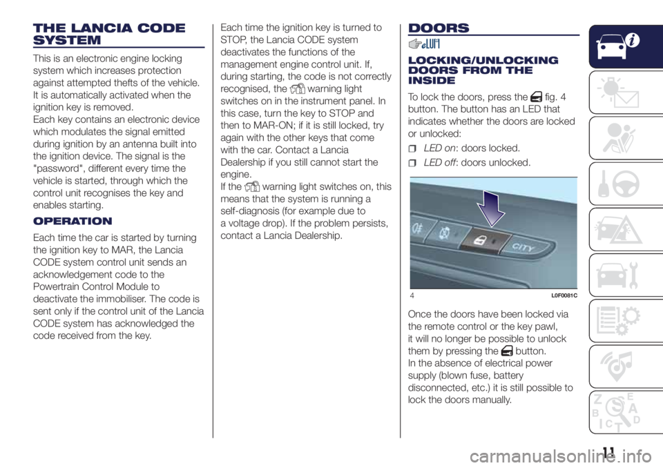
To lock the doors, press the
fig. 4
button. The button has an LED that
indicates whether the doors are locked
or unlocked:
LED on: doors locked.
LED off: doors unlocked.
Once the doors have been locked via
the remote control or the key pawl,
it will no longer be possible to unlock
them by pressing the
button.
In the absence of electrical power
supply (blown fuse, battery
disconnected, etc.) it is still possible to
lock the doors manually.
4L0F0081C
11
Page 14 of 200
IMPORTANT With central locking
active, pulling the internal opening lever
of the passenger side door unlocks
the door (the LED stays on). Pulling the
internal opening lever of the driver
side door activates central unlocking.
IMPORTANT The rear doors cannot be
opened from the inside when the
child-lock system is engaged (see the
description in the following paragraph).
LOCKING/UNLOCKING
DOORS FROM THE
OUTSIDE
Mechanical key:insert the metal
insert in the lock and turn it.
Key with remote control: press the
button to lock the doors, or the
button to unlock the doors.
SAFE LOCK DEVICE
2)
This safety device inhibits the operation
of the interior door handles and the
door locking/unlocking button.
Activating the device
The device is enabled on all the doors
by pressing the
button on the key
twice quickly.
The direction indicators flash 3 times
and the LED above the
fig. 4 button
flashes to indicate that the device has
been activated.Deactivating the device
The device disengages automatically:
pressing thebutton on the remote
control;
by turning the ignition key to the
MAR position.
CHILD SAFETY DEVICE
7)3)
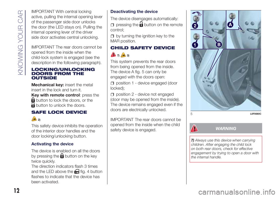
This system prevents the rear doors
from being opened from the inside.
The device A fig. 5 can only be
engaged with the doors open:
position 1 - device engaged (door
locked);
position 2 - device not engaged
(door may be opened from the inside).
The device remains engaged even if the
doors are electrically unlocked.
IMPORTANT The rear doors cannot be
opened from the inside when the child
safety device is engaged.
WARNING
7)Always use this device when carrying
children. After engaging the child lock
on both rear doors, check for effective
engagement by trying to open a door with
the internal handle.
5L0F0080C
12
KNOWING YOUR CAR
Page 15 of 200
WARNING
2)Once the Safe Lock system is engaged,
it is impossible to open the doors from
inside the car. Therefore, before getting out
of the car check that there is no one left
on board.
3)If the child lock and the the front
passenger door and rear doors emergency
lock device are engaged, operating the
internal opening handle will not open the
door: in this case, to open the door, the
outside handle must be used. The door
central locking/unlocking button
is not
disabled by the engagement of the
emergency lock.
SEATS
8) 9)4)
FRONT SEATS
Longitudinal adjustment
10)
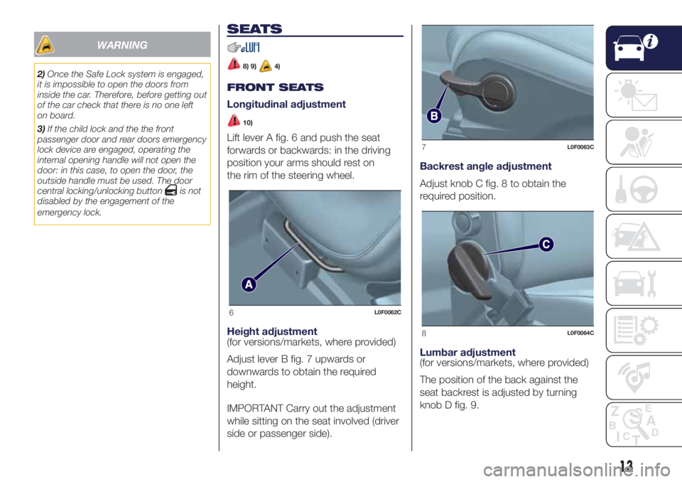
Lift lever A fig. 6 and push the seat
forwards or backwards: in the driving
position your arms should rest on
the rim of the steering wheel.
Height adjustment
(for versions/markets, where provided)
Adjust lever B fig. 7 upwards or
downwards to obtain the required
height.
IMPORTANT Carry out the adjustment
while sitting on the seat involved (driver
side or passenger side).Backrest angle adjustment
Adjust knob C fig. 8 to obtain the
required position.
Lumbar adjustment
(for versions/markets, where provided)
The position of the back against the
seat backrest is adjusted by turning
knob D fig. 9.
6L0F0062C
7L0F0063C
8L0F0064C
13
Page 16 of 200
REAR SEATS
11)5)
Extending the boot
Proceed as follows:
Remove the head restraints by
pulling them upwards as described in
the "Headrests" paragraph in this
chapter;
move the seat belts to the side,
making sure that they are correctly
extended and not twisted;
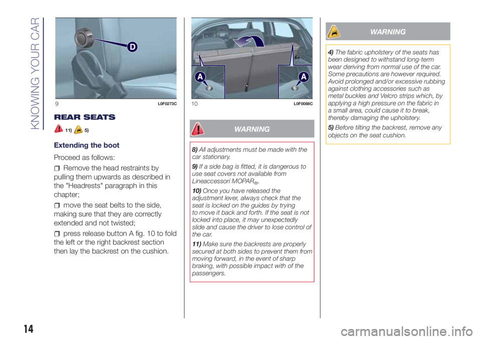
press release button A fig. 10 to fold
the left or the right backrest section
then lay the backrest on the cushion.
WARNING
8)All adjustments must be made with the
car stationary.
9)If a side bag is fitted, it is dangerous to
use seat covers not available from
Lineaccessori MOPAR
®.
10)Once you have released the
adjustment lever, always check that the
seat is locked on the guides by trying
to move it back and forth. If the seat is not
locked into place, it may unexpectedly
slide and cause the driver to lose control of
the car.
11)Make sure the backrests are properly
secured at both sides to prevent them from
moving forward, in the event of sharp
braking, with possible impact with of the
passengers.
WARNING
4)The fabric upholstery of the seats has
been designed to withstand long-term
wear deriving from normal use of the car.
Some precautions are however required.
Avoid prolonged and/or excessive rubbing
against clothing accessories such as
metal buckles and Velcro strips which, by
applying a high pressure on the fabric in
a small area, could cause it to break,
thereby damaging the upholstery.
5)Before tilting the backrest, remove any
objects on the seat cushion.
9L0F0273C10L0F0088C
14
KNOWING YOUR CAR
Page 17 of 200
HEADRESTS
12) 13)
FRONT HEAD
RESTRAINTS
They are height-adjustable: to adjust
them operate as follows.
Upwards adjustment: raise the head
restraint until it clicks into place.
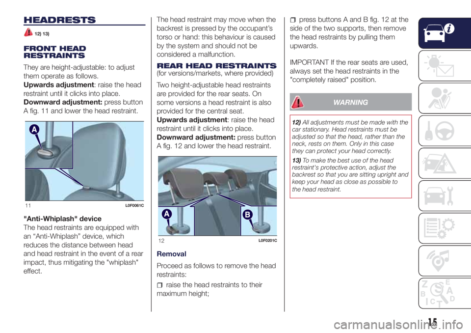
Downward adjustment:press button
A fig. 11 and lower the head restraint.
"Anti-Whiplash" device
The head restraints are equipped with
an “Anti-Whiplash” device, which
reduces the distance between head
and head restraint in the event of a rear
impact, thus mitigating the "whiplash"
effect.The head restraint may move when the
backrest is pressed by the occupant’s
torso or hand: this behaviour is caused
by the system and should not be
considered a malfunction.
REAR HEAD RESTRAINTS
(for versions/markets, where provided)
Two height-adjustable head restraints
are provided for the rear seats. On
some versions a head restraint is also
provided for the central seat.
Upwards adjustment: raise the head
restraint until it clicks into place.
Downward adjustment:press button
A fig. 12 and lower the head restraint.
Removal
Proceed as follows to remove the head
restraints:
raise the head restraints to their
maximum height;
press buttons A and B fig. 12 at the
side of the two supports, then remove
the head restraints by pulling them
upwards.
IMPORTANT If the rear seats are used,
always set the head restraints in the
"completely raised" position.
WARNING
12)All adjustments must be made with the
car stationary. Head restraints must be
adjusted so that the head, rather than the
neck, rests on them. Only in this case
they can protect your head correctly.
13)To make the best use of the head
restraint's protective action, adjust the
backrest so that you are sitting upright and
keep your head as close as possible to
the head restraint.
11L0F0061C
12L0F0201C
15
Page 18 of 200
STEERING WHEEL
14) 15)
ADJUSTMENTS
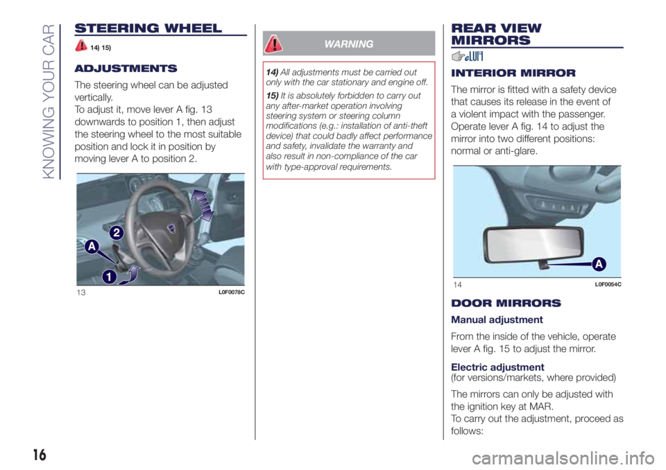
The steering wheel can be adjusted
vertically.
To adjust it, move lever A fig. 13
downwards to position 1, then adjust
the steering wheel to the most suitable
position and lock it in position by
moving lever A to position 2.
WARNING
14)All adjustments must be carried out
only with the car stationary and engine off.
15)It is absolutely forbidden to carry out
any after-market operation involving
steering system or steering column
modifications (e.g.: installation of anti-theft
device) that could badly affect performance
and safety, invalidate the warranty and
also result in non-compliance of the car
with type-approval requirements.
REAR VIEW
MIRRORS
INTERIOR MIRROR
The mirror is fitted with a safety device
that causes its release in the event of
a violent impact with the passenger.
Operate lever A fig. 14 to adjust the
mirror into two different positions:
normal or anti-glare.
DOOR MIRRORS
Manual adjustment
From the inside of the vehicle, operate
lever A fig. 15 to adjust the mirror.
Electric adjustment
(for versions/markets, where provided)
The mirrors can only be adjusted with
the ignition key at MAR.
To carry out the adjustment, proceed as
follows:
13L0F0078C14L0F0054C
16
KNOWING YOUR CAR
Page 19 of 200
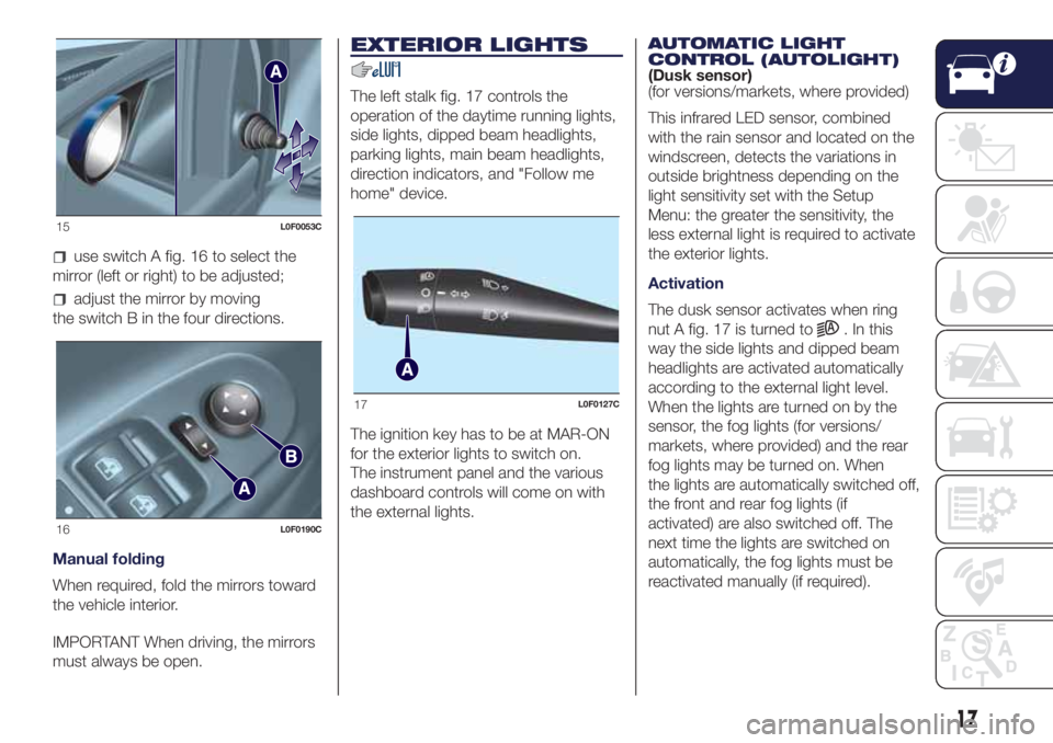
use switch A fig. 16 to select the
mirror (left or right) to be adjusted;
adjust the mirror by moving
the switch B in the four directions.
Manual folding
When required, fold the mirrors toward
the vehicle interior.
IMPORTANT When driving, the mirrors
must always be open.
EXTERIOR LIGHTS
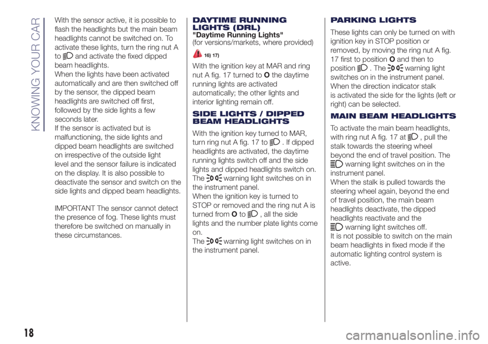
The left stalk fig. 17 controls the
operation of the daytime running lights,
side lights, dipped beam headlights,
parking lights, main beam headlights,
direction indicators, and "Follow me
home" device.
The ignition key has to be at MAR-ON
for the exterior lights to switch on.
The instrument panel and the various
dashboard controls will come on with
the external lights.AUTOMATIC LIGHT
CONTROL (AUTOLIGHT)
(Dusk sensor)
(for versions/markets, where provided)
This infrared LED sensor, combined
with the rain sensor and located on the
windscreen, detects the variations in
outside brightness depending on the
light sensitivity set with the Setup
Menu: the greater the sensitivity, the
less external light is required to activate
the exterior lights.
Activation
The dusk sensor activates when ring
nut A fig. 17 is turned to
. In this
way the side lights and dipped beam
headlights are activated automatically
according to the external light level.
When the lights are turned on by the
sensor, the fog lights (for versions/
markets, where provided) and the rear
fog lights may be turned on. When
the lights are automatically switched off,
the front and rear fog lights (if
activated) are also switched off. The
next time the lights are switched on
automatically, the fog lights must be
reactivated manually (if required).
15L0F0053C
16L0F0190C
17L0F0127C
17
Page 20 of 200
With the sensor active, it is possible to
flash the headlights but the main beam
headlights cannot be switched on. To
activate these lights, turn the ring nut A
to
and activate the fixed dipped
beam headlights.
When the lights have been activated
automatically and are then switched off
by the sensor, the dipped beam
headlights are switched off first,
followed by the side lights a few
seconds later.
If the sensor is activated but is
malfunctioning, the side lights and
dipped beam headlights are switched
on irrespective of the outside light
level and the sensor failure is indicated
on the display. It is also possible to
deactivate the sensor and switch on the
side lights and dipped beam headlights.
IMPORTANT The sensor cannot detect
the presence of fog. These lights must
therefore be switched on manually in
these circumstances.DAYTIME RUNNING
LIGHTS (DRL)
"Daytime Running Lights"
(for versions/markets, where provided)16) 17)
With the ignition key at MAR and ring
nut A fig. 17 turned toOthe daytime
running lights are activated
automatically; the other lights and
interior lighting remain off.
SIDE LIGHTS / DIPPED
BEAM HEADLIGHTS
With the ignition key turned to MAR,
turn ring nut A fig. 17 to
. If dipped
headlights are activated, the daytime
running lights switch off and the side
lights and dipped headlights switch on.
The
warning light switches on in
the instrument panel.
When the ignition key is turned to
STOP or removed and the ring nut A is
turned fromOto
, all the side
lights and the number plate lights come
on.
The
warning light switches on in
the instrument panel.PARKING LIGHTS
These lights can only be turned on with
ignition key in STOP position or
removed, by moving the ring nut A fig.
17 first to positionOand then to
position
. Thewarning light
switches on in the instrument panel.
When the direction indicator stalk
is activated the side for the lights (left or
right) can be selected.
MAIN BEAM HEADLIGHTS
To activate the main beam headlights,
with ring nut A fig. 17 at
, pull the
stalk towards the steering wheel
beyond the end of travel position. The
warning light switches on in the
instrument panel.
When the stalk is pulled towards the
steering wheel again, beyond the end
of travel position, the main beam
headlights deactivate, the dipped
headlights reactivate and the
warning light switches off.
It is not possible to switch on the main
beam headlights in fixed mode if the
automatic lighting control system is
active.
18
KNOWING YOUR CAR