clock Lancia Ypsilon 2016 Owner handbook (in English)
[x] Cancel search | Manufacturer: LANCIA, Model Year: 2016, Model line: Ypsilon, Model: Lancia Ypsilon 2016Pages: 200, PDF Size: 4.53 MB
Page 30 of 200
ELECTRIC SUN
ROOF
(for versions/markets, where provided)
21)12)
The large electric sun roof comprises
two glass panels; the front one is
mobile and the rear one fixed. These
are equipped with two sun blinds (front
and rear) that can be moved manually.
With the sun roof closed, the blinds can
be placed in any position.
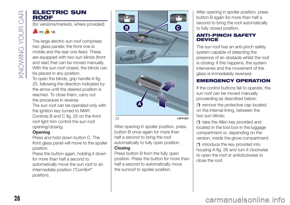
To open the blinds, grip handle A fig.
25, following the direction indicated by
the arrow until the desired position is
reached. To close them, carry out
the procedure in reverse.
The sun roof can be operated only with
the ignition key turned to MAR.
Controls B and C fig. 25 on the front
roof light trim control the sun roof
opening/closing.
Opening
Press and hold down button C. The
front glass panel will move to the spoiler
position.
Press the button again, holding it down
for more than half a second to
automatically move the sun roof to an
intermediate position (“Comfort”
position).After opening in spoiler position, press
button B once again for more than
half a second to bring the roof
automatically to fully open position.
Closing
Press button B from the fully open
position. Press the button for more than
half a second to automatically move
the sunroof to spoiler position.After opening in spoiler position, press
button B again for more than half a
second to bring the roof automatically
to fully closed position.
ANTI-PINCH SAFETY
DEVICE
The sun roof has an anti-pinch safety
system capable of detecting the
presence of an obstacle whilst the roof
is closing: if this happens, the system
intervenes and the movement of the
glass is immediately reversed.
EMERGENCY OPERATION
If the control buttons fail to operate, the
sun roof can be moved manually
proceeding as described below:
remove the protective cap located
on the internal lining, between the
two sun blinds;
take the Allen key provided and
located in the tool box in the luggage
compartment or, depending on the
version, inside the glove compartment;
introduce the key provided into
housing A fig. 26 and turn it clockwise
to open the roof or anticlockwise to
close the roof.
25L0F0152C
28
KNOWING YOUR CAR
Page 35 of 200
WARNING
26)A heavy load that has not been
secured may cause serious injuries to
passengers in the event of an accident.
27)If you are travelling in an area with
limited opportunities for vehicle refuelling
and you wish to bring petrol with you in
a petrol can, you must do so in compliance
with current regulations and using an
approved can, appropriately secured to the
load securing attachments. In the event of
a collision the fire risk is increased all the
same.
28)Be careful not to hit objects on the
storage shelf when you open the tailgate.
VERSION WITH LPG
SYSTEM
INTRODUCTION
29)14) 15)
The LPG version features two fuel
supply systems: one for petrol and one
for LPG.
Although the LPG system has
numerous safety features, it is advisable
to proceed as follows every time the
car is not in use for a long period or
moved in an emergency as a result of a
breakdown or accident:
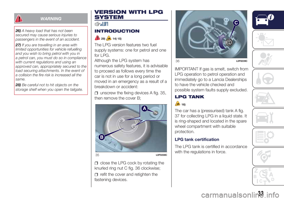
unscrew the fixing devices A fig. 35,
then remove the cover B;
close the LPG cock by rotating the
knurled ring nut C fig. 36 clockwise;
refit the cover and retighten the
fastening devices.IMPORTANT If gas is smelt, switch from
LPG operation to petrol operation and
immediately go to a Lancia Dealerships
to have the vehicle checked and
possible system faults supply excluded.
LPG TANK
16)
The car has a (pressurised) tank A fig.
37 for collecting LPG in a liquid state. It
is ring-shaped and located in the spare
wheel compartment with suitable
protection.
LPG tank certification
The LPG tank is certified in accordance
with the regulations in force.
35L0F0238C
36L0F0239C
33
Page 37 of 200
WARNING
14)The car is equipped with a gaseous
LPG injection system designed specifically
for it: it is therefore absolutely forbidden
to alter the configuration of the system or
its components. The use of other
components or materials could cause
malfunctions and lead to a reduction
in safety. If you experience problems, go to
a Lancia Dealership. When towing or
lifting the vehicle, follow the instructions in
the main handbook under the paragraph
on "Towing the vehicle" to prevent damage
to the gas system parts.
15)When using a painting oven, the LPG
tank should be removed from the car
and later carefully refitted at a Lancia
Dealership. Although the LPG system has
numerous safety features, it is advisable
to proceed as follows every time the
vehicle is not in use for a long period or
moved in an emergency as a result of
a breakdown or accident: unscrew the
fastening devices A fig. 35, then remove
the cover B. Close the LPG cock rotating
the ring nut C fig. 36 clockwise. Refit
the cover and retighten the fastening
devices.
16)Periodically (at least once every six
months) it is advisable to let the LPG in the
tank run out and, at the first refuelling, to
check that it does not exceed the
maximum capacity of 30.5 litres (reserve
included) (with a tolerance of 2 litres
excess). If the level is above 30.5 litres
(reserve included) contact a Lancia
Dealership immediately.17)The system operates at temperatures
ranging between -20°C and 100°C.
18)If, during LPG operation, LPG runs out,
the system automatically switches to
petrol operation as indicated by thewarning light on the display.
19)Regardless of the last fuel system
used, at the following engine starting, after
the initial petrol stage, the system will
automatically switch to LPG.
20)When switching is requested, metallic
noise from the valves which pressurise
the circuit can be heard. For the switching
logic described above, a delay between the
valve ticking and the switching off of the
instrument panel indication is completely
normal.
21)In particular usage conditions, such as
starting and operation at low ambient
temperature or LPG supply with low
propane content, the system may switch
temporarily to petrol operation, without
a visual indication of switching on the
instrument panel. In the event of low LPG
levels in the tank or request for high
performance (e.g. overtaking, car fully
laden, steep hills) the system may
automatically switch to petrol operation to
guarantee the engine power requested; the
icon
on the display switches on to
indicate this. When the above conditions
are no longer present, the system
automatically restores LPG operation and
the
icon switches off. To achieve the
automatic switching described above,
make sure that there is always enough fuel
in the petrol tank.
22)It is strictly forbidden to use any
additive in the LPG.
VERSION WITH
METHANE SYSTEM
(Natural Power)
31) 32)
INTRODUCTION
The "Natural Power" version features
two fuel systems, one for petrol and
one for natural gas (methane).
METHANE CYLINDERS
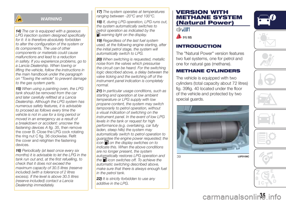
The vehicle is equipped with two
cylinders (total capacity about 72 litres)
fig. 39fig. 40 located under the floor
of the vehicle and protected by two
special guards.
39L0F0106C
35
Page 105 of 200
WARNING
119)The ABS with which the car is
equipped will not control the braking
system of the trailer. Particular caution is
required on slippery roads.
120)Never modify the braking system of
the vehicle to control the trailer brake.
The trailer braking system must be fully
independent of the car’s hydraulic system.
REFUELLING THE
VEHICLE
46) 47) 48)
Always stop the engine before
refuelling.
PETROL ENGINES
Only use unleaded petrol, with an
octane number (R.O.N.) not lower than
95.
In order to prevent damage to the
catalytic converter never introduce even
the smallest amount of leaded petrol,
even in the event of an emergency.
DIESEL ENGINES
49)
Only use Diesel for motor vehicles (EN
590 specification).
When using or parking the vehicle for a
long time in the mountains or cold
areas, it is advisable to refuel using
locally available diesel. In this case, it is
also advisable to keep the tank over
50% full.REFUELLING
PROCEDURE
Petrol and Diesel versions equipped
with fuel tank cap
(for versions/markets, where provided)
To refuel proceed as follows:
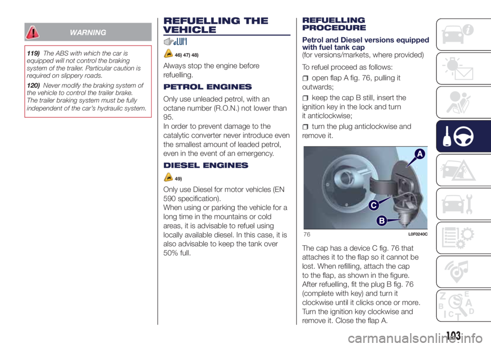
open flap A fig. 76, pulling it
outwards;
keep the cap B still, insert the
ignition key in the lock and turn
it anticlockwise;
turn the plug anticlockwise and
remove it.
The cap has a device C fig. 76 that
attaches it to the flap so it cannot be
lost. When refilling, attach the cap
to the flap, as shown in the figure.
After refuelling, fit the plug B fig. 76
(complete with key) and turn it
clockwise until it clicks once or more.
Turn the ignition key clockwise and
remove it. Close the flap A.
76L0F0240C
103
Page 107 of 200
hand the special filler adapter (see
the following description) over to the
qualified LPG refuelling personnel.
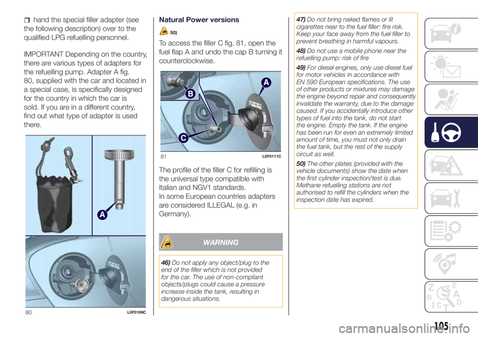
IMPORTANT Depending on the country,
there are various types of adapters for
the refuelling pump. Adapter A fig.
80, supplied with the car and located in
a special case, is specifically designed
for the country in which the car is
sold. If you are in a different country,
find out what type of adapter is used
there.Natural Power versions
50)
To access the filler C fig. 81, open the
fuel flap A and undo the cap B turning it
counterclockwise.
The profile of the filler C for refilling is
the universal type compatible with
Italian and NGV1 standards.
In some European countries adapters
are considered ILLEGAL (e.g. in
Germany).
WARNING
46)Do not apply any object/plug to the
end of the filler which is not provided
for the car. The use of non-compliant
objects/plugs could cause a pressure
increase inside the tank, resulting in
dangerous situations.47)Do not bring naked flames or lit
cigarettes near to the fuel filler: fire risk.
Keep your face away from the fuel filler to
prevent breathing in harmful vapours.
48)Do not use a mobile phone near the
refuelling pump: risk of fire
49)For diesel engines, only use diesel fuel
for motor vehicles in accordance with
EN 590 European specifications. The use
of other products or mixtures may damage
the engine beyond repair and consequently
invalidate the warranty, due to the damage
caused. If you accidentally introduce other
types of fuel into the tank, do not start
the engine. Empty the tank. If the engine
has been run for even an extremely limited
amount of time, you must not only drain
the fuel tank, but the rest of the supply
circuit as well.
50)The other plates (provided with the
vehicle documents) show the date when
the first cylinder inspection/test is due.
Methane refuelling stations are not
authorised to refill the cylinders when the
inspection date has expired.
80L0F0199C
81L0F0111C
105
Page 111 of 200

REPLACING AN
EXTERNAL BULB
FRONT LIGHT CLUSTERS
These contain the bulbs for the daytime
running lights (DRL), side lights,
dipped/main beam headlights and
direction indicators.
The bulbs are arranged as follows fig.
83:
Daytime running lights (DRL)
Dipped/main beam headlights and
side lights
Direction indicators
Daytime running lights (DRL)
To replace the bulb, proceed as follows:
remove cover A fig. 83;
turn the snap-fitted bulb holder unit
B fig. 84 anticlockwise, remove bulb
C and replace it;
refit the new bulb then reinsert the
bulb holder B fig. 84 in its housing;
then refit the cover A fig. 83.
Side lights
To replace the bulb, proceed as follows:
remove cover B fig. 83;
remove snap-fitted bulb holder C fig.
85, remove the bulb D and replace it;
refit the new bulb then reinsert
the bulb holder unit C fig. 85 in
its housing;
then refit the cover B fig. 83.
Dipped/main beam headlights
To replace the bulb, proceed as follows:
remove the cover B fig. 83 and
then the snap-fitted bulb holder C fig.
86;
remove bulb D from the connector E
and replace it;
refit the new bulb on the connector
making sure that it is locked correctly,
then reinsert bulb holder C in its
housing;
then refit the cover B fig. 83.
Front direction indicators
To replace the bulb, proceed as follows:
turn the cover C fig. 83
anticlockwise, extract the bulb D fig. 87
from its housing and replace it;
83L0F0033C
84L0F0070C
85L0F0069C
86L0F0068C
109
Page 112 of 200

refit the bulb D in the housing E and
then fit the cover C fig. 83.
Side direction indicators
To replace the bulb, proceed as follows:
adjust the lens A fig. 89 to
compress in the internal catch B, then
pull the unit outwards;
turn the bulb holder C anticlockwise,
extract the bulb and replace it;
refit the bulb holder C in the lens and
turn it clockwise;
refit the cluster making sure that the
internal catch B clips into position.
Front fog lights
(for versions/markets, where provided)
To replace the bulb, proceed as follows:
steer the wheel completely, adjust
the tabs A fig. 89 and remove the
flap B;
adjust the clip C fig. 90 and
disconnect the electrical connector D;
remove the cover E by turning it
clockwise (see the word OFF and the
arrow on the cover);
release the catches F fig. 91
removing them outwards;
release the connector G fig. 92 and
replace the bulb H;
87L0F0071C
88L0F0209C
89L0F0205C
90L0F0206C
91L0F0207C
92L0F0208C
110
IN AN EMERGENCY
Page 113 of 200

refit the new lamp and carry out the
procedure described previously in
reverse.
REAR LIGHT CLUSTERS
These contain the bulbs for the side
lights, brake lights and direction
indicators. The reversing lights and rear
fog lights are located instead in the
rear bumper.
The bulbs are arranged as follows fig.
93:A- Direction indicators
B- Brake lights
Direction indicators/brake lights
Turn the bulb holder in directionO
(open) to replace the bulbs. After
replacing the bulb, turn the bulb holder
in directionC(close).
Side lights
These are LEDs. Contact a Lancia
Dealership for replacement.
THIRD BRAKE LIGHTS
These are located in the tailgate and
are LED lights. Contact a Lancia
Dealership for replacement.
REVERSING LIGHT/REAR FOG
LIGHT
To replace the bulb, proceed as follows:
working from inside the bumper,
turn the bulb holder unit A fig. 94 by a
1/4 turn;
extract the bulb and replace it;
refit the new bulb then reinsert the
bulb holder in its housing.
NUMBER PLATE LIGHTS
To replace the bulbs proceed as
follows:
remove lens A fig. 95;
turn the bulb holder B fig. 96
clockwise, extract the bulb C and
replace it; then refit the lens.
93L0F0034C
94L0F0219C
95L0F0259C
96L0F0214C
111
Page 176 of 200
SWITCHING THE SYSTEM
ON/OFF
The system is switched on/off by
pressing the
(ON/OFF) button/knob.
Turn the button/knob clockwise to
increase the radio volume or
anticlockwise to decrease it.
The system is equipped with the
following tuners: AM, FM and DAB (for
versions/markets, where provided).
RADIO MODE
Press the RADIO button on the front
panel to activate radio mode.
After the desired radio station is
selected, the following information is
shown on the display:
At the top: the list of radio stations
stored (preset) is displayed; the station
currently playing is highlighted.
In the middle: display of the name of
the current radio station and the
buttons for selecting the previous or
next radio station.
At the bottom: display of the following
buttons:
"Browse": list of the radio stations
available;
"AM/FM", "AM/DAB", "FM/DAB":
selection of the desired frequency band
(button reconfigurable according to
the band selected: AM, FM or DAB);
"Tune" : manual radio station tuning
(not available for DAB radios);
"Info": additional information on the
source being listened to;
"Audio": access to the "Audio
settings" screen.
Radio station selection
To search for the desired radio station
press buttons
oron the display
or use the steering wheel controls.
Previous/next radio station search
Briefly press buttons
oron
the display: when the button is released
the previous or the next radio station
is displayed.
Previous/next radio station fast
search
Hold down buttons
oron the
display to start fast search: when the
button is released, the first tunable
radio station can be heard.
Audio menu
To access the "Audio" menu press the
Audio" button located at the bottom
of the display.
The following adjustments can be
carried out using the "Audio" menu:
"Equaliser" (for versions/markets,
where provided);
"Balance/Fader" (left/right and
front/rear audio balance adjustment);
"Speed/Volume" (speed-dependent
automatic volume control);
"Loudness" (for versions/markets,
where provided);
"Auto-On Radio";
"Radio Off Delay".
To exit the "Audio" menu, press the
/Done button.
MEDIA MODE
Audio source selection
Press the "Source" button to select the
desired audio source among those
available: AUX, USB, iPod or
Bluetooth®.
NOTE Applications used on portable
devices may be not compatible with the
Uconnect™system
Track change
Briefly press the
button or turn the
BROWSE ENTER button/knob
clockwise to play the next track or
briefly press the
button or turn the
BROWSE ENTER button/knob
anticlockwise to return to the beginning
of the selected track or to the beginning
of the previous track if it has been
played for less than 3 seconds.
174
MULTIMEDIA
Page 182 of 200
Trip data storage and transfer
The trip data can be stored in
the system memory and transferred
using a suitably configured USB flash
drive orUconnect™LIVE App. This
allows you to display the history of
the collected data, showing the
complete analysis of the trip data and
of your driving style.
Further information is available at
www.driveuconnect.eu.
IMPORTANT Do not remove the USB
memory stick nor unpair the
smartphone and theUconnect™LIVE
Appbefore the system has
downloaded the data, since these
could be lost. During the transfer of
data to the devices, messages may
appear on the radio display to guide the
user correctly through the operation;
follow these instructions. These
messages are only displayed with the
ignition key at STOP and when a delay
in the system switching off is set. The
data are automatically transferred to the
devices when the engine is switched
off. Transferred data will be deleted
from the system memory in this
manner. You can choose to store the
trip data or not, by pressing the
"Settings" button and by setting the
storage activation and the USB or
Cloud transfer mode.When the USB memory stick is full, the
warning messages are shown on the
radio display.
When theeco:Drive™ data are not
transferred to USB memory stick for a
long time, the internal memory of the
Uconnect™LIVEsystem may be
exhausted. Follow the instructions given
by the messages on the radio display.
SETTINGS
Press SETTINGS button
on the
front panel (versions withUconnect™
5” Radio LIVE) or the APPS button
on the front panel and then the
“Settings” graphic button (versions with
Uconnect™ 5” Radio Nav LIVE) on
the display to view the “Settings” main
menu.
NOTE The menu items displayed vary
according to the versions.
The menu includes the following items:
Display;
Units;
Voice controls;
Clock & Date;
Safety (for versions/markets where
provided)
Lights (for versions/markets where
provided);
Doors & Locks;
Vehicle Off Options;
Audio;
Phone / Bluetooth;
Configurat. SiriusXM (for versions/
markets where provided);
Radio Setup;
Restore settings;
Clear Personal Data.
Safety
(for versions/markets, where provided)
This function can be used to carry
out the following adjustments:
"Rain sensor"(for versions/markets,
where provided): this function can be
used to activate/deactivate the
automatic operation of the wipers in the
event of rain.
NAVIGATION
(Uconnect™ 5" Radio Nav LIVE only)
IMPORTANT In the interest of safety
and to reduce distractions while you are
driving, you should always plan a route
before you start driving.
To plan a route, do the following:
tap the screen to open the Main
menu;
Tap "Navigate to" or "Drive to".
Tap "Address". You can change the
country or state setting by tapping
the flag before you select a city.
180
MULTIMEDIA