wheel Lancia Ypsilon 2020 Owner handbook (in English)
[x] Cancel search | Manufacturer: LANCIA, Model Year: 2020, Model line: Ypsilon, Model: Lancia Ypsilon 2020Pages: 200, PDF Size: 4.53 MB
Page 93 of 200
Pretensioners and airbags are deployed
in different ways on the basis of the
type of collision. Failure to activate one
or more of the devices does not
indicate a system malfunction.
94) 95) 96) 97) 98) 99) 100) 101) 102) 103) 104) 105)
106)
WARNING
91)Do not apply stickers or other objects
on the steering wheel, on the dashboard in
the passenger side airbag area, on side
upholstery on the roof or on the seats.
Never put objects (e.g. mobile phones) on
the passenger side of the dashboard
since they could interfere with correct
inflation of the passenger airbag and also
cause serious injury to the passengers.
92)Always drive with your hands on the
rim of the steering wheel so that the airbag
can inflate freely if required. Do not drive
with your body bent forward. Keep your
back straight against the backrest.93)When there is an active passenger
airbag, DO NOT install rearward facing
child restraint systems on the front seat.
Deployment of the airbag in an accident
could cause fatal injuries to the child
regardless of the severity of the impact.
Therefore, always deactivate the passenger
side airbag when a rearward facing child
restraint system is installed on the front
passenger seat. The front passenger seat
must also be positioned back as far as
possible in order to prevent the child
restraint system from coming into contact
with the dashboard. Immediately reactivate
the passenger airbag as soon as the child
restraint system has been removed.
94)Do not affix rigid objects to the garment
hooks or support handles.
95)Do not rest your head, arms or elbows
on the door, windows or the area in which
the window bag is located to avoid
possible injury during airbag inflation.
96)Never lean your head, arms or elbows
out of the window.
97)If, when the key is turned to MAR, the
warning light does not switch on or
stays on whilst driving, a fault may have
occurred in the restraint systems. In this
case the airbags or pretensioners may not
be deployed in an impact or, in a lower
number of cases, they may be deployed
accidentally. Before continuing, contact
a Lancia Dealership immediately to have
the system checked.
98)For versions/markets where provided,
in the event of
warning light failure,
thewarning light switches on and the
explosive charges of the passenger airbag
are deactivated.99)On cars with side bags, do not cover
the front seat backrests with extra covers.
100)Do not travel carrying objects in
your lap, in front of your chest or between
your lips (pipe, pencils, etc.): they could
cause severe injury if the airbag is
deployed.
101)If your car has been subject to theft,
attempted theft, vandalism, or flooding,
contact a Lancia Dealership to have the
airbag system checked.
102)The airbags may also be deployed
when the car is not moving, if the key is in
the ignition and turned to MAR-ON or
when the engine is off, if the car is hit by
another moving vehicle. Therefore, even if
the vehicle is stationary, when an active
front passenger airbag is fitted, DO NOT
install rearward facing child restraint
systems on the front passenger seat.
Deployment of the airbag following an
impact could cause fatal injuries to the
child. Therefore, always deactivate the
passenger side airbag when a rearward
facing child restraint system is installed on
the front passenger seat. The front
passenger seat must also be positioned
back as far as possible in order to prevent
the child restraint system from coming
into contact with the dashboard.
Immediately reactivate the passenger
airbag as soon as the child restraint system
has been removed. Also remember that, if
the key is turned to STOP, none of the
safety devices (airbags or pretensioners)
will be deployed in the event of collision.
Non-deployment in such cases does
not indicate a system malfunction.
91
Page 97 of 200
WARNING
107)It is dangerous to run the engine in
enclosed areas. The engine consumes
oxygen and engine exhaust contains
carbon dioxide, carbon monoxide and
other toxic gasses.
108)Remember that the brake servo and
power steering are not operational until the
engine has been started, therefore much
effort than usual is required on the brake
pedal and steering wheel.
109)If the engine fails to start with a gear
engaged, the potentially dangerous
situation due to the fact that the gearbox is
automatically placed in neutral will be
signalled by a buzzer.
WARNING
34)The flashing of the warning lightfor
60 seconds after starting or during
prolonged cranking of the engine indicates
a fault with the glow plug heating system.
You can use the car as usual if the engine
starts but you should contact a Lancia
Dealership as soon as possible.
35)It is advisable not to demand maximum
performance from your car (e.g. excessive
acceleration, long distances at maximum
rpm, excessively intense braking, etc.)
when it is first used.
36)When the engine is switched off never
leave the key turned to MAR-ON to prevent
useless current absorption from draining
the battery.37)Never, under any circumstances, jump
start the engine by pushing, towing or
coasting downhill. This could cause fuel to
flow into the catalytic converter and
damage it beyond repair.
38)There must therefore always be
enough petrol in the tank to protect the
petrol pump and to guarantee temporary
switching from methane to petrol
operation, if high performance is required.
39)A quick burst on the accelerator before
turning off the engine serves absolutely
no practical purpose, it wastes fuel and is
especially damaging to turbocharged
engines.
HANDBRAKE
110) 111) 112)
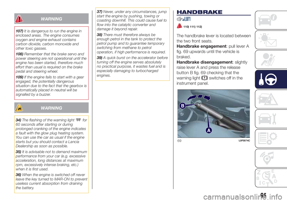
The handbrake lever is located between
the two front seats.
Handbrake engagement: pull lever A
fig. 69 upwards until the vehicle is
braked.
Handbrake disengagement: slightly
raise lever A and press the release
button B fig. 69 checking that the
warning light
switches off in the
instrument panel.
69L0F0074C
95
Page 98 of 200
WARNING
110)Never leave children unattended in
the car. Always remove the key from the
ignition when leaving the car and take
it with you.
111)The car should be braked after a few
clicks of the lever, if it is not, contact a
Lancia Dealership to have it adjusted.
112)In the case of parking manoeuvres on
roads on a gradient, the front wheels
must be steered towards the pavement
(when parking downhill), or in the opposite
direction if the vehicle is parked uphill.
Block the wheels with a wedge or a stone if
the car is parked on a steep slope.
MANUAL GEARBOX
113)40)
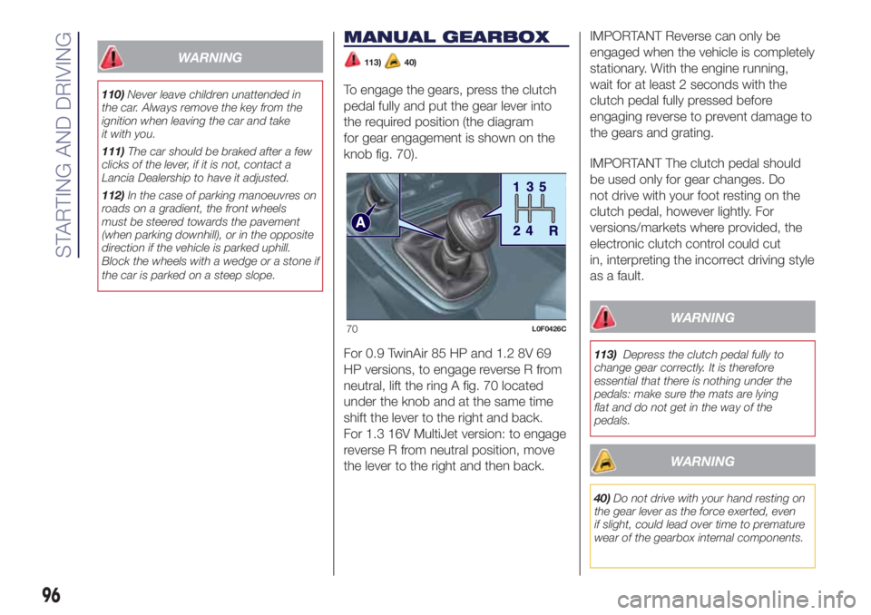
To engage the gears, press the clutch
pedal fully and put the gear lever into
the required position (the diagram
for gear engagement is shown on the
knob fig. 70).
For 0.9 TwinAir 85 HP and 1.2 8V 69
HP versions, to engage reverse R from
neutral, lift the ring A fig. 70 located
under the knob and at the same time
shift the lever to the right and back.
For 1.3 16V MultiJet version: to engage
reverse R from neutral position, move
the lever to the right and then back.IMPORTANT Reverse can only be
engaged when the vehicle is completely
stationary. With the engine running,
wait for at least 2 seconds with the
clutch pedal fully pressed before
engaging reverse to prevent damage to
the gears and grating.
IMPORTANT The clutch pedal should
be used only for gear changes. Do
not drive with your foot resting on the
clutch pedal, however lightly. For
versions/markets where provided, the
electronic clutch control could cut
in, interpreting the incorrect driving style
as a fault.
WARNING
113)Depress the clutch pedal fully to
change gear correctly. It is therefore
essential that there is nothing under the
pedals: make sure the mats are lying
flat and do not get in the way of the
pedals.
WARNING
40)Do not drive with your hand resting on
the gear lever as the force exerted, even
if slight, could lead over time to premature
wear of the gearbox internal components.
70L0F0426C
96
STARTING AND DRIVING
Page 100 of 200

IMPORTANT The use of the “Kick
Down” function is recommended only
when overtaking or accelerating quickly,
in order not to increase fuel
consumption.
STEERING WHEEL CONTROLS
(for versions/markets, where provided)
42)
On some versions, the gearbox can be
managed sequentially using the
steering wheel controls fig. 72.
To use the controls on the steering
wheel, the gear lever must be in the
central position between + and – :
operating the + lever: engage
a higher gear;
operating the – lever: engage a
lower gear.
The engagement of a lower (or higher)
gear is only permitted if the engine
rpm allow it.
WARNING
41)Avoid keeping your hand placed on this
lever in between gear changes or
Auto/Manual mode.
42)Using the paddles incorrectly (paddles
pushed towards the dashboard) could
break them.
STOP/START
SYSTEM
(for versions/markets, where provided)
114) 115)43)
The Stop/Start system automatically
stops the engine each time the vehicle
is stationary and starts it again when
the driver wants to move off. In this
way, the vehicle efficiency is increased,
by reducing consumption, dangerous
gas emissions and sound pollution.
OPERATING MODES
Stopping the engine
With manual gearbox: with the car
stationary, the engine stops with the
gearbox in neutral and the clutch pedal
released.
With Dual FuNction System gearbox:
the engine stops if the vehicle is at
a standstill and the brake pedal is
pressed. This condition can be
maintained even if the brake pedal is
not depressed, if the gear lever is
in position N (Neutral).
NOTE The engine can only be stopped
automatically after exceeding a speed
of about 10 km/h, to prevent the engine
from being repeatedly stopped when
driving at walking pace.
72L0F0431C
98
STARTING AND DRIVING
Page 106 of 200
Petrol and Diesel versions equipped
with "Smart Fuel" system
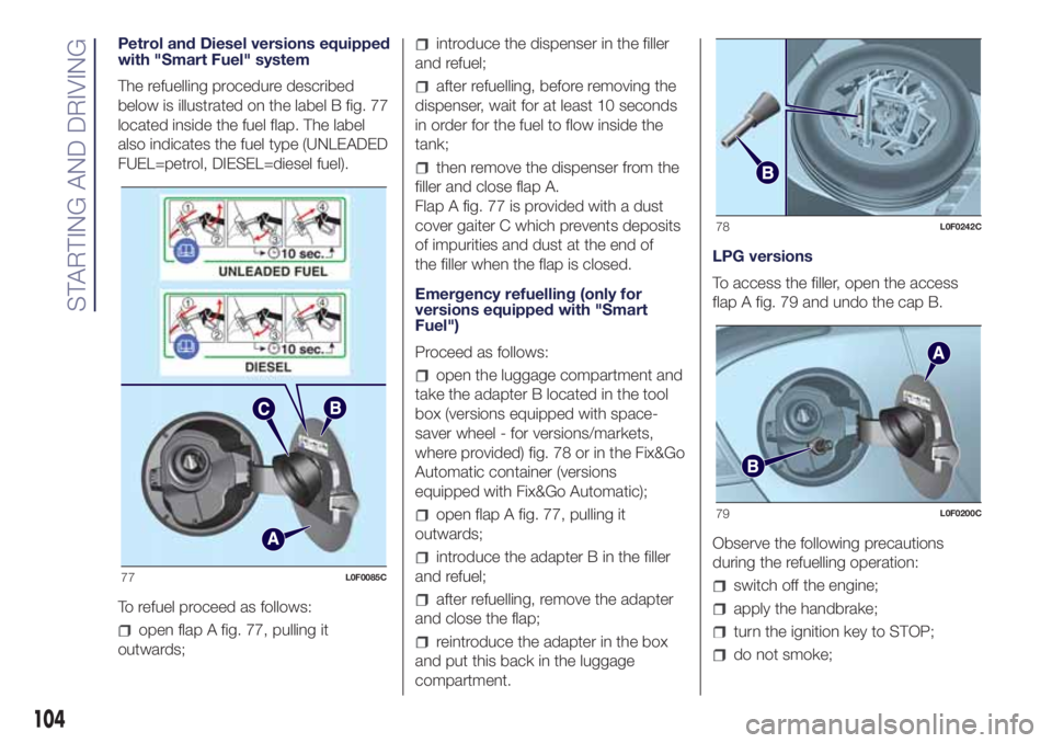
The refuelling procedure described
below is illustrated on the label B fig. 77
located inside the fuel flap. The label
also indicates the fuel type (UNLEADED
FUEL=petrol, DIESEL=diesel fuel).
To refuel proceed as follows:
open flap A fig. 77, pulling it
outwards;
introduce the dispenser in the filler
and refuel;
after refuelling, before removing the
dispenser, wait for at least 10 seconds
in order for the fuel to flow inside the
tank;
then remove the dispenser from the
filler and close flap A.
Flap A fig. 77 is provided with a dust
cover gaiter C which prevents deposits
of impurities and dust at the end of
the filler when the flap is closed.
Emergency refuelling (only for
versions equipped with "Smart
Fuel")
Proceed as follows:
open the luggage compartment and
take the adapter B located in the tool
box (versions equipped with space-
saver wheel - for versions/markets,
where provided) fig. 78 or in the Fix&Go
Automatic container (versions
equipped with Fix&Go Automatic);
open flap A fig. 77, pulling it
outwards;
introduce the adapter B in the filler
and refuel;
after refuelling, remove the adapter
and close the flap;
reintroduce the adapter in the box
and put this back in the luggage
compartment.LPG versions
To access the filler, open the access
flap A fig. 79 and undo the cap B.
Observe the following precautions
during the refuelling operation:
switch off the engine;
apply the handbrake;
turn the ignition key to STOP;
do not smoke;
77L0F0085C
78L0F0242C
79L0F0200C
104
STARTING AND DRIVING
Page 108 of 200
IN AN EMERGENCY
A punctured tyre or a burnt-out bulb?
At times, a problem may interfere
with our journey.
The pages on emergencies can help
you to deal with critical situations
independently and with calm.
In an emergency we recommend that
you call the freephone number found in
the Warranty Booklet.
It is also possible to call the national or
international universal freephone
number to search for the nearest
Dealership.HAZARD WARNING LIGHTS...........107
REPLACING A BULB ......................107
REPLACING FUSES........................112
REPLACING A WHEEL ...................117
"FIX&GO AUTOMATIC" KIT .............120
EMERGENCY STARTING ................122
FUEL CUT-OFF SYSTEM ................124
TOWING THE VEHICLE ..................124
106
IN AN EMERGENCY
Page 112 of 200

refit the bulb D in the housing E and
then fit the cover C fig. 83.
Side direction indicators
To replace the bulb, proceed as follows:
adjust the lens A fig. 89 to
compress in the internal catch B, then
pull the unit outwards;
turn the bulb holder C anticlockwise,
extract the bulb and replace it;
refit the bulb holder C in the lens and
turn it clockwise;
refit the cluster making sure that the
internal catch B clips into position.
Front fog lights
(for versions/markets, where provided)
To replace the bulb, proceed as follows:
steer the wheel completely, adjust
the tabs A fig. 89 and remove the
flap B;
adjust the clip C fig. 90 and
disconnect the electrical connector D;
remove the cover E by turning it
clockwise (see the word OFF and the
arrow on the cover);
release the catches F fig. 91
removing them outwards;
release the connector G fig. 92 and
replace the bulb H;
87L0F0071C
88L0F0209C
89L0F0205C
90L0F0206C
91L0F0207C
92L0F0208C
110
IN AN EMERGENCY
Page 119 of 200
REPLACING A
WHEEL
129) 130) 131) 132) 133) 134) 135)
54) 55)
JACK
Please note that:
the jack weight is 1,76 kg;
the jack requires no adjustment;
the jack cannot be repaired and in
the event of a fault it must be replaced
by another genuine one;
no tool other than its cranking
device may be fitted on the jack.
CHANGING PROCEDURE
To change a wheel, proceed as follows:
stop the car in a position that is
not dangerous for oncoming traffic
where you can change the wheel safely.
The ground must be flat and sufficiently
compact;
switch off the engine, pull up the
handbrake and engage the 1stgear or
reverse. Wear the reflective safety
jacket (compulsory by law) before
getting out of the car;
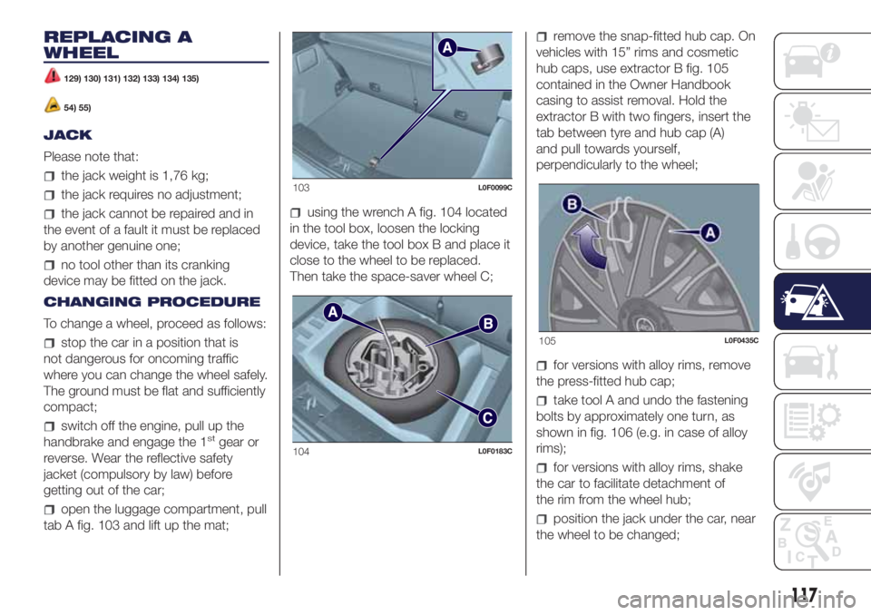
open the luggage compartment, pull
tab A fig. 103 and lift up the mat;
using the wrench A fig. 104 located
in the tool box, loosen the locking
device, take the tool box B and place it
close to the wheel to be replaced.
Then take the space-saver wheel C;
remove the snap-fitted hub cap. On
vehicles with 15” rims and cosmetic
hub caps, use extractor B fig. 105
contained in the Owner Handbook
casing to assist removal. Hold the
extractor B with two fingers, insert the
tab between tyre and hub cap (A)
and pull towards yourself,
perpendicularly to the wheel;
for versions with alloy rims, remove
the press-fitted hub cap;
take tool A and undo the fastening
bolts by approximately one turn, as
shown in fig. 106 (e.g. in case of alloy
rims);
for versions with alloy rims, shake
the car to facilitate detachment of
the rim from the wheel hub;
position the jack under the car, near
the wheel to be changed;
103L0F0099C
104L0F0183C
105L0F0435C
117
Page 120 of 200

operate the device A fig. 107 to
extend the jack until the top part B fig.
108 fits correctly into the side member
C (next to the mark
on the side
member);
alert any bystander that the car is
about to be raised; all persons should
be kept away from the car and nobody
must touch it until it has been lowered;
fit handle D fig. 107 into the housing
in device A, operate the jack and raise
the vehicle until the wheel is a few
centimetres from the ground;
loosen the bolts completely and
remove the wheel to be replaced;
make sure the contact surfaces
between space-saver wheel and hub
are clean so that the fastening bolts will
not come loose;
fit the space-saver wheel by
inserting the first bolt for two threads
into the hole closest to the valve;
take the wrench A fig. 106 and fully
tighten the fixing bolts;
operate the jack handle D to lower
the car. Then extract the jack;
use the wrench A provided to fully
tighten the bolts in a criss-cross fashion
as per the numerical sequence
illustrated in fig. 109;
when replacing a wheel with alloy
rim it is advisable to place it upside
down in the boot with the cosmetic part
facing upwards.
Restore the standard wheel as soon as
possible, because, once placed in the
associated compartment, the luggage
compartment load platform is rendered
uneven as the standard wheel is larger
than the space-saver wheel.
REFITTING THE
STANDARD WHEEL
Following the procedure described
previously, raise the vehicle and remove
the space-saver wheel.
Versions with steel wheels
Proceed as follows:
make sure the contact surfaces
between standard wheel and hub are
clean so that the fastening bolts will not
come loose;
106L0F0179C
107L0F0025C
108L0F0024C
109L0F0182C
118
IN AN EMERGENCY
Page 121 of 200
fit the standard wheel inserting the 4
bolts into the holes;
using the wrench provided, tighten
the fastening bolts;
lower the vehicle and remove the
jack;
using the wrench provided, fully
tighten the bolts in the sequence
shown previously.
press-fit the wheel cap, aligning the
special splining (on the cap) with the
inflation valve;
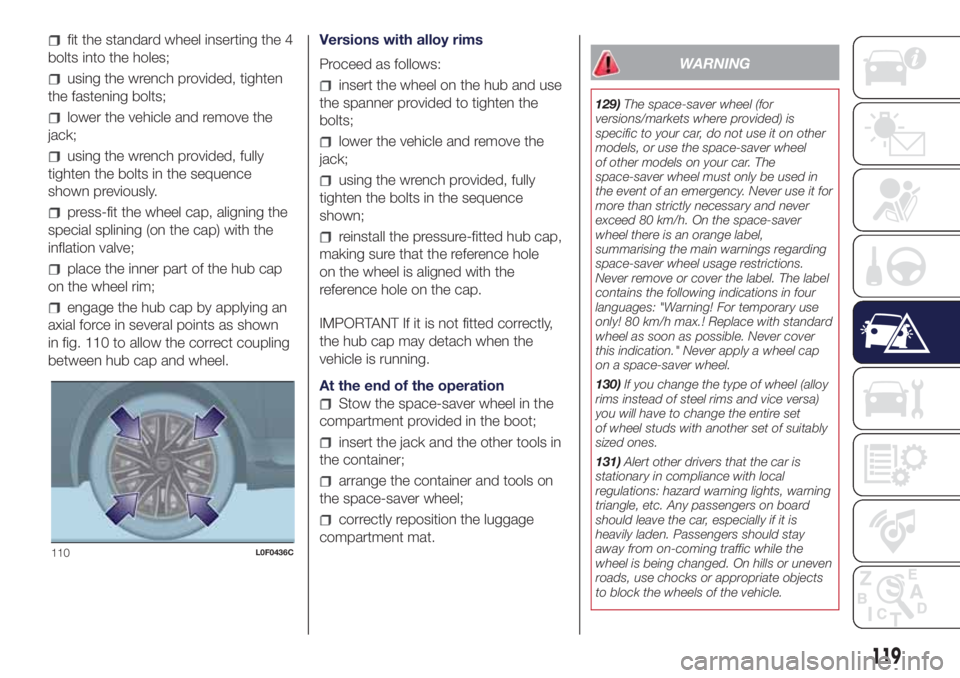
place the inner part of the hub cap
on the wheel rim;
engage the hub cap by applying an
axial force in several points as shown
in fig. 110 to allow the correct coupling
between hub cap and wheel.Versions with alloy rims
Proceed as follows:
insert the wheel on the hub and use
the spanner provided to tighten the
bolts;
lower the vehicle and remove the
jack;
using the wrench provided, fully
tighten the bolts in the sequence
shown;
reinstall the pressure-fitted hub cap,
making sure that the reference hole
on the wheel is aligned with the
reference hole on the cap.
IMPORTANT If it is not fitted correctly,
the hub cap may detach when the
vehicle is running.
At the end of the operation
Stow the space-saver wheel in the
compartment provided in the boot;
insert the jack and the other tools in
the container;
arrange the container and tools on
the space-saver wheel;
correctly reposition the luggage
compartment mat.
WARNING
129)The space-saver wheel (for
versions/markets where provided) is
specific to your car, do not use it on other
models, or use the space-saver wheel
of other models on your car. The
space-saver wheel must only be used in
the event of an emergency. Never use it for
more than strictly necessary and never
exceed 80 km/h. On the space-saver
wheel there is an orange label,
summarising the main warnings regarding
space-saver wheel usage restrictions.
Never remove or cover the label. The label
contains the following indications in four
languages: "Warning! For temporary use
only! 80 km/h max.! Replace with standard
wheel as soon as possible. Never cover
this indication." Never apply a wheel cap
on a space-saver wheel.
130)If you change the type of wheel (alloy
rims instead of steel rims and vice versa)
you will have to change the entire set
of wheel studs with another set of suitably
sized ones.
131)Alert other drivers that the car is
stationary in compliance with local
regulations: hazard warning lights, warning
triangle, etc. Any passengers on board
should leave the car, especially if it is
heavily laden. Passengers should stay
away from on-coming traffic while the
wheel is being changed. On hills or uneven
roads, use chocks or appropriate objects
to block the wheels of the vehicle.
110L0F0436C
119