boot Lancia Ypsilon 2020 Owner handbook (in English)
[x] Cancel search | Manufacturer: LANCIA, Model Year: 2020, Model line: Ypsilon, Model: Lancia Ypsilon 2020Pages: 200, PDF Size: 4.53 MB
Page 9 of 200
KNOWING YOUR CAR
In-depth knowledge of your new vehicle
starts here.
The booklet that you are reading simply
and directly explains how it is made
and how it works.
That’s why we advise you to read it
seated comfortably on board, so that
you can see immediately what is
described here for yourself.INSTRUMENT PANEL ..................... 8
THE KEYS ...................................... 9
IGNITION DEVICE ........................... 10
THE LANCIA CODE SYSTEM.......... 11
DOORS ........................................... 11
SEATS ............................................ 13
HEADRESTS ................................... 15
STEERING WHEEL ......................... 16
REAR VIEW MIRRORS .................... 16
EXTERIOR LIGHTS ......................... 17
INTERIOR LIGHTS .......................... 20
WINDSCREEN / REAR WINDOW
WIPERS .......................................... 21
CLIMATE CONTROL ....................... 23
ELECTRIC WINDOWS .................... 27
ELECTRIC SUN ROOF .................... 28
CONTROLS .................................... 29
BONNET ......................................... 30
BOOT ............................................. 32
VERSION WITH LPG SYSTEM ........ 33
VERSION WITH METHANE
SYSTEM (NATURAL POWER) ......... 35
7
Page 16 of 200
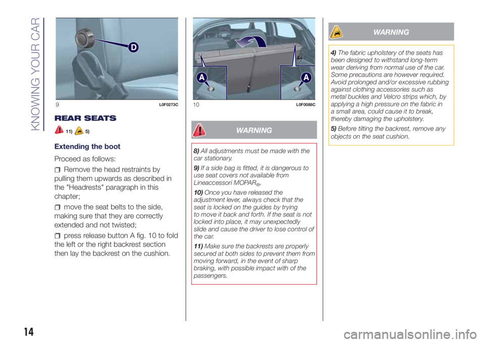
REAR SEATS
11)5)
Extending the boot
Proceed as follows:
Remove the head restraints by
pulling them upwards as described in
the "Headrests" paragraph in this
chapter;
move the seat belts to the side,
making sure that they are correctly
extended and not twisted;
press release button A fig. 10 to fold
the left or the right backrest section
then lay the backrest on the cushion.
WARNING
8)All adjustments must be made with the
car stationary.
9)If a side bag is fitted, it is dangerous to
use seat covers not available from
Lineaccessori MOPAR
®.
10)Once you have released the
adjustment lever, always check that the
seat is locked on the guides by trying
to move it back and forth. If the seat is not
locked into place, it may unexpectedly
slide and cause the driver to lose control of
the car.
11)Make sure the backrests are properly
secured at both sides to prevent them from
moving forward, in the event of sharp
braking, with possible impact with of the
passengers.
WARNING
4)The fabric upholstery of the seats has
been designed to withstand long-term
wear deriving from normal use of the car.
Some precautions are however required.
Avoid prolonged and/or excessive rubbing
against clothing accessories such as
metal buckles and Velcro strips which, by
applying a high pressure on the fabric in
a small area, could cause it to break,
thereby damaging the upholstery.
5)Before tilting the backrest, remove any
objects on the seat cushion.
9L0F0273C10L0F0088C
14
KNOWING YOUR CAR
Page 34 of 200
BOOT
26) 27)
The luggage compartment unlocking is
electrically operated and is deactivated
when the car is in motion.
OPENING
26)
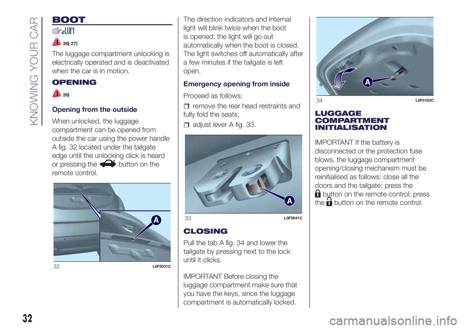
Opening from the outside
When unlocked, the luggage
compartment can be opened from
outside the car using the power handle
A fig. 32 located under the tailgate
edge until the unlocking click is heard
or pressing the
button on the
remote control.The direction indicators and internal
light will blink twice when the boot
is opened: the light will go out
automatically when the boot is closed.
The light switches off automatically after
a few minutes if the tailgate is left
open.
Emergency opening from inside
Proceed as follows:
remove the rear head restraints and
fully fold the seats;
adjust lever A fig. 33.
CLOSING
Pull the tab A fig. 34 and lower the
tailgate by pressing next to the lock
until it clicks.
IMPORTANT Before closing the
luggage compartment make sure that
you have the keys, since the luggage
compartment is automatically locked.LUGGAGE
COMPARTMENT
INITIALISATION
IMPORTANT If the battery is
disconnected or the protection fuse
blows, the luggage compartment
opening/closing mechanism must be
reinitialised as follows: close all the
doors and the tailgate; press the
button on the remote control; press
the
button on the remote control.
32L0F0031C
33L0F0041C
34L0F0193C
32
KNOWING YOUR CAR
Page 120 of 200

operate the device A fig. 107 to
extend the jack until the top part B fig.
108 fits correctly into the side member
C (next to the mark
on the side
member);
alert any bystander that the car is
about to be raised; all persons should
be kept away from the car and nobody
must touch it until it has been lowered;
fit handle D fig. 107 into the housing
in device A, operate the jack and raise
the vehicle until the wheel is a few
centimetres from the ground;
loosen the bolts completely and
remove the wheel to be replaced;
make sure the contact surfaces
between space-saver wheel and hub
are clean so that the fastening bolts will
not come loose;
fit the space-saver wheel by
inserting the first bolt for two threads
into the hole closest to the valve;
take the wrench A fig. 106 and fully
tighten the fixing bolts;
operate the jack handle D to lower
the car. Then extract the jack;
use the wrench A provided to fully
tighten the bolts in a criss-cross fashion
as per the numerical sequence
illustrated in fig. 109;
when replacing a wheel with alloy
rim it is advisable to place it upside
down in the boot with the cosmetic part
facing upwards.
Restore the standard wheel as soon as
possible, because, once placed in the
associated compartment, the luggage
compartment load platform is rendered
uneven as the standard wheel is larger
than the space-saver wheel.
REFITTING THE
STANDARD WHEEL
Following the procedure described
previously, raise the vehicle and remove
the space-saver wheel.
Versions with steel wheels
Proceed as follows:
make sure the contact surfaces
between standard wheel and hub are
clean so that the fastening bolts will not
come loose;
106L0F0179C
107L0F0025C
108L0F0024C
109L0F0182C
118
IN AN EMERGENCY
Page 121 of 200
fit the standard wheel inserting the 4
bolts into the holes;
using the wrench provided, tighten
the fastening bolts;
lower the vehicle and remove the
jack;
using the wrench provided, fully
tighten the bolts in the sequence
shown previously.
press-fit the wheel cap, aligning the
special splining (on the cap) with the
inflation valve;
place the inner part of the hub cap
on the wheel rim;
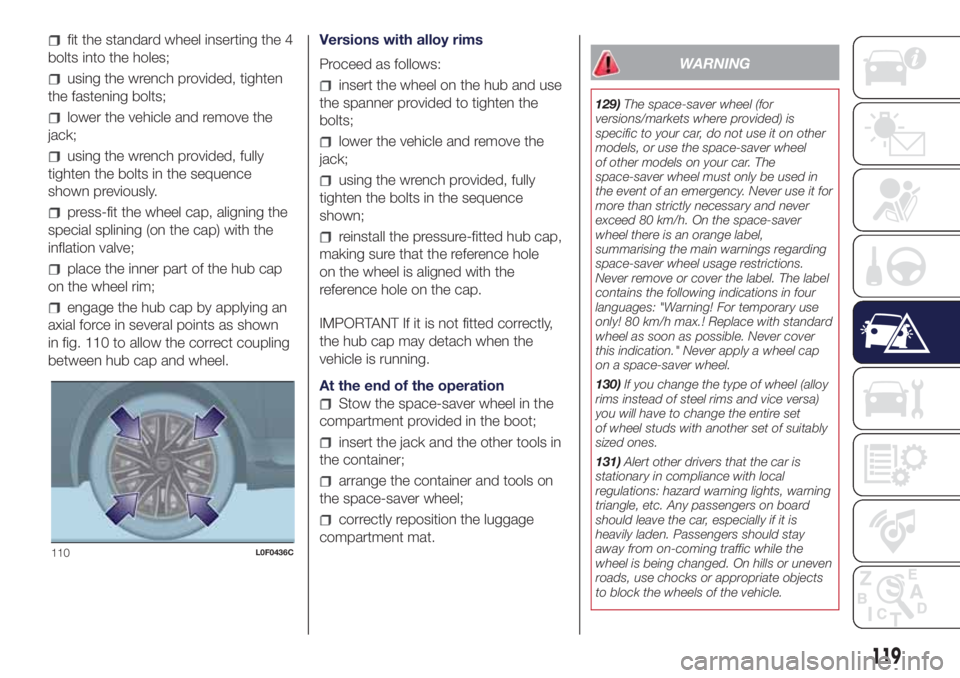
engage the hub cap by applying an
axial force in several points as shown
in fig. 110 to allow the correct coupling
between hub cap and wheel.Versions with alloy rims
Proceed as follows:
insert the wheel on the hub and use
the spanner provided to tighten the
bolts;
lower the vehicle and remove the
jack;
using the wrench provided, fully
tighten the bolts in the sequence
shown;
reinstall the pressure-fitted hub cap,
making sure that the reference hole
on the wheel is aligned with the
reference hole on the cap.
IMPORTANT If it is not fitted correctly,
the hub cap may detach when the
vehicle is running.
At the end of the operation
Stow the space-saver wheel in the
compartment provided in the boot;
insert the jack and the other tools in
the container;
arrange the container and tools on
the space-saver wheel;
correctly reposition the luggage
compartment mat.
WARNING
129)The space-saver wheel (for
versions/markets where provided) is
specific to your car, do not use it on other
models, or use the space-saver wheel
of other models on your car. The
space-saver wheel must only be used in
the event of an emergency. Never use it for
more than strictly necessary and never
exceed 80 km/h. On the space-saver
wheel there is an orange label,
summarising the main warnings regarding
space-saver wheel usage restrictions.
Never remove or cover the label. The label
contains the following indications in four
languages: "Warning! For temporary use
only! 80 km/h max.! Replace with standard
wheel as soon as possible. Never cover
this indication." Never apply a wheel cap
on a space-saver wheel.
130)If you change the type of wheel (alloy
rims instead of steel rims and vice versa)
you will have to change the entire set
of wheel studs with another set of suitably
sized ones.
131)Alert other drivers that the car is
stationary in compliance with local
regulations: hazard warning lights, warning
triangle, etc. Any passengers on board
should leave the car, especially if it is
heavily laden. Passengers should stay
away from on-coming traffic while the
wheel is being changed. On hills or uneven
roads, use chocks or appropriate objects
to block the wheels of the vehicle.
110L0F0436C
119
Page 130 of 200
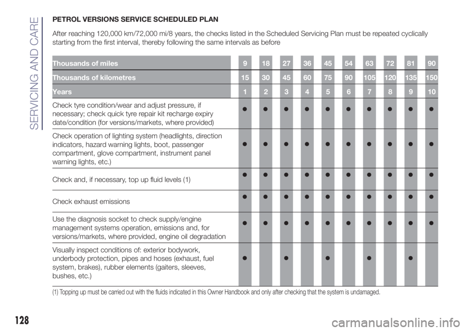
PETROL VERSIONS SERVICE SCHEDULED PLAN
After reaching 120,000 km/72,000 mi/8 years, the checks listed in the Scheduled Servicing Plan must be repeated cyclically
starting from the first interval, thereby following the same intervals as before
Thousands of miles 9 18 27 36 45 54 63 72 81 90
Thousands of kilometres 15 30 45 60 75 90 105 120 135 150
Years12345678910
Check tyre condition/wear and adjust pressure, if
necessary; check quick tyre repair kit recharge expiry
date/condition (for versions/markets, where provided)
Check operation of lighting system (headlights, direction
indicators, hazard warning lights, boot, passenger
compartment, glove compartment, instrument panel
warning lights, etc.)
Check and, if necessary, top up fluid levels (1)
Check exhaust emissions
Use the diagnosis socket to check supply/engine
management systems operation, emissions and, for
versions/markets, where provided, engine oil degradation
Visually inspect conditions of: exterior bodywork,
underbody protection, pipes and hoses (exhaust, fuel
system, brakes), rubber elements (gaiters, sleeves,
bushes, etc.)
(1) Topping up must be carried out with the fluids indicated in this Owner Handbook and only after checking that the system is undamaged.
128
SERVICING AND CARE
Page 135 of 200
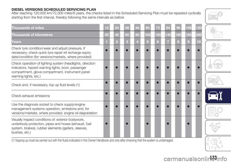
DIESEL VERSIONS SCHEDULED SERVICING PLAN
After reaching 120,000 km/72,000 miles/6 years, the checks listed in the Scheduled Servicing Plan must be repeated cyclically
starting from the first interval, thereby following the same intervals as before
Thousands of miles 12 24 36 48 60 72 84 96 108 120
Thousands of kilometres 20 40 60 80 100 120 140 160 180 200
Years12345678910
Check tyre condition/wear and adjust pressure, if
necessary; check quick tyre repair kit recharge expiry
date/condition (for versions/markets, where provided)
Check operation of lighting system (headlights, direction
indicators, hazard warning lights, boot, passenger
compartment, glove compartment, instrument panel
warning lights, etc.)
Check and, if necessary, top up fluid levels (1)
Check exhaust emissions
Use the diagnosis socket to check supply/engine
management systems operation, emissions and, for
versions/markets, where provided, engine oil degradation
Visually inspect conditions of: exterior bodywork,
underbody protection, pipes and hoses (exhaust, fuel
system, brakes), rubber elements (gaiters, sleeves,
bushes, etc.)
(1) Topping up must be carried out with the fluids indicated in this Owner Handbook and only after checking that the system is undamaged.
133
Page 150 of 200
IDENTIFICATION
DATA
It is advisable to take note of the
identification codes. The following
identification codes are printed and
shown on the plates:
VIN plate.
Chassis marking.
Bodywork paint identification plate.
Engine marking.
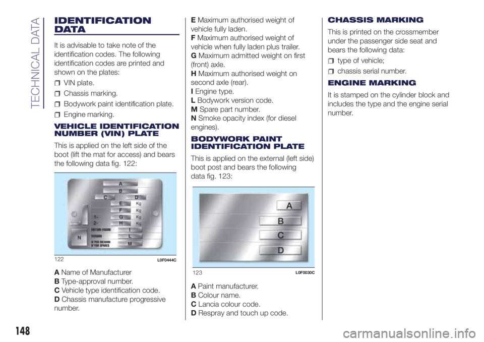
VEHICLE IDENTIFICATION
NUMBER (VIN) PLATE
This is applied on the left side of the
boot (lift the mat for access) and bears
the following data fig. 122:
AName of Manufacturer
BType-approval number.
CVehicle type identification code.
DChassis manufacture progressive
number.EMaximum authorised weight of
vehicle fully laden.
FMaximum authorised weight of
vehicle when fully laden plus trailer.
GMaximum admitted weight on first
(front) axle.
HMaximum authorised weight on
second axle (rear).
IEngine type.
LBodywork version code.
MSpare part number.
NSmoke opacity index (for diesel
engines).
BODYWORK PAINT
IDENTIFICATION PLATE
This is applied on the external (left side)
boot post and bears the following
data fig. 123:
APaint manufacturer.
BColour name.
CLancia colour code.
DRespray and touch up code.CHASSIS MARKING
This is printed on the crossmember
under the passenger side seat and
bears the following data:
type of vehicle;
chassis serial number.
ENGINE MARKING
It is stamped on the cylinder block and
includes the type and the engine serial
number.
123L0F0030C
148
TECHNICAL DATA
122L0F0444C
Page 197 of 200
INDEX
A
BS system........................66
Active safety systems................66
ASR system.........................67
Automatic climate control
system...........................25
BAt system.........................68
Battery............................142
Bodywork (cleaning and
maintenance)....................145
Bonnet.............................30
Boot................................32
Brakes............................144
brake fluid level.................140
Car dimensions...................155
Carrying children safely
child restraint systems...........82
Changes or alterations to the car...................................4
Checking levels....................137
Child protection systems.............76
Climate control......................23
CO
2emissions....................165
Control panel and on-board
instruments.......................39
Controls............................29
Cruise Control.......................99
Daytime running lights (DRL)........18
Demanding use of the car..........136
Diesel versions scheduled
servicing plan....................133Dipped headlights...................18
Direction indicators..................19
Display.............................41
Doors...............................11
Driving assistance systems..........70
EBD system........................66
Electric windows....................27
Emergency starting................122
Engine
engine coolant level............140
technical specifications.........149
Engine compartment...............137
Engine compartment (washing).....146
Engine oil
consumption...................140
Engine oil (level check)..............140
ESC system.........................66
Extending the boot..................14
Exterior lights.......................17
Fix&Go automatic (kit).............120
Fluids and lubricants...............160
Follow Me Home (device)............19
Front ceiling lights...................20
Front fog lights......................19
Fuel consumption..................164
Fuel cut-off system.................124
Fuses
dashboard fuse box............113
engine compartment fuse
box ............................112luggage compartment fuse
box ............................113
Fuses (replacement)................112
Gear Shift Indicator.................41
Gearbox (operation).................97
Handbrake.........................95
Hazard warning lights..............107
HBA system........................68
Head restraint.......................15
Headlights (cleaning)...............146
HH system..........................66
Identification data
chassis marking................148
engine marking.................148
Identification data plate.............148
Ignition device.......................10
Important information and
recommendations...............185
Instrument panel......................8
Interior lights........................20
iTPMS..............................70
Jack..............................117
Lancia CODE.......................11
Lifting the car......................144
Luggage compartment
(capacity)........................155
Main beam headlights..............18
Manual gearbox.....................96
Mechanical Brake Assist.............66
MSR system........................68