buttons Lancia Ypsilon 2020 Owner handbook (in English)
[x] Cancel search | Manufacturer: LANCIA, Model Year: 2020, Model line: Ypsilon, Model: Lancia Ypsilon 2020Pages: 200, PDF Size: 4.53 MB
Page 10 of 200
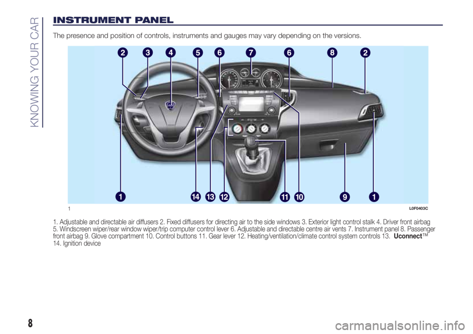
INSTRUMENT PANEL
The presence and position of controls, instruments and gauges may vary depending on the versions.
1. Adjustable and directable air diffusers 2. Fixed diffusers for directing air to the side windows 3. Exterior light control stalk 4. Driver front airbag
5. Windscreen wiper/rear window wiper/trip computer control lever 6. Adjustable and directable centre air vents 7. Instrument panel 8. Passenger
front airbag 9. Glove compartment 10. Control buttons 11. Gear lever 12. Heating/ventilation/climate control system controls 13.Uconnect™
14. Ignition device
1L0F0403C
8
KNOWING YOUR CAR
Page 17 of 200
HEADRESTS
12) 13)
FRONT HEAD
RESTRAINTS
They are height-adjustable: to adjust
them operate as follows.
Upwards adjustment: raise the head
restraint until it clicks into place.
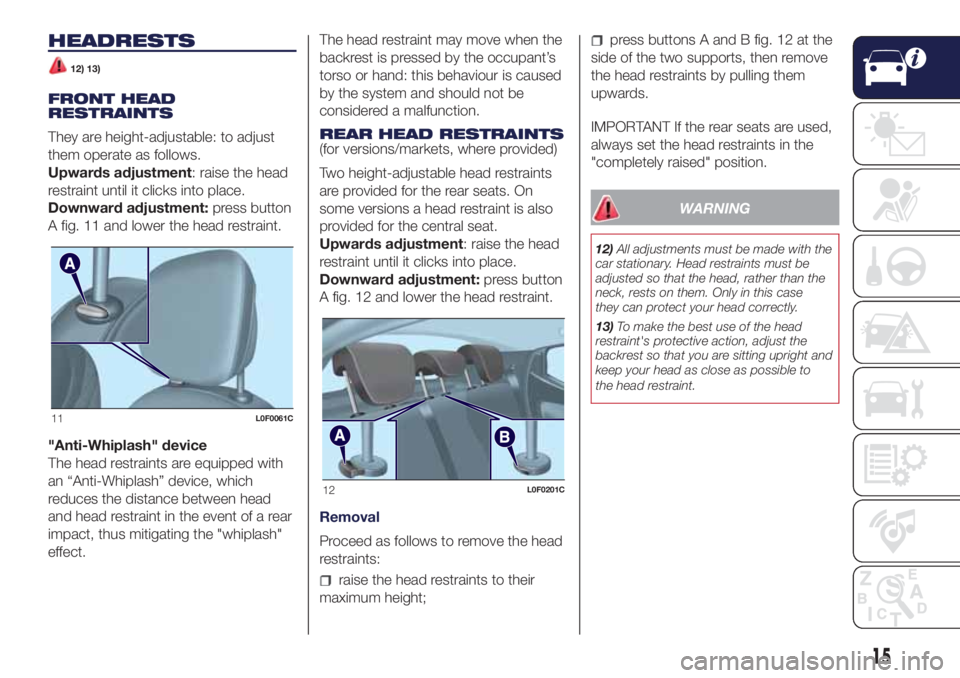
Downward adjustment:press button
A fig. 11 and lower the head restraint.
"Anti-Whiplash" device
The head restraints are equipped with
an “Anti-Whiplash” device, which
reduces the distance between head
and head restraint in the event of a rear
impact, thus mitigating the "whiplash"
effect.The head restraint may move when the
backrest is pressed by the occupant’s
torso or hand: this behaviour is caused
by the system and should not be
considered a malfunction.
REAR HEAD RESTRAINTS
(for versions/markets, where provided)
Two height-adjustable head restraints
are provided for the rear seats. On
some versions a head restraint is also
provided for the central seat.
Upwards adjustment: raise the head
restraint until it clicks into place.
Downward adjustment:press button
A fig. 12 and lower the head restraint.
Removal
Proceed as follows to remove the head
restraints:
raise the head restraints to their
maximum height;
press buttons A and B fig. 12 at the
side of the two supports, then remove
the head restraints by pulling them
upwards.
IMPORTANT If the rear seats are used,
always set the head restraints in the
"completely raised" position.
WARNING
12)All adjustments must be made with the
car stationary. Head restraints must be
adjusted so that the head, rather than the
neck, rests on them. Only in this case
they can protect your head correctly.
13)To make the best use of the head
restraint's protective action, adjust the
backrest so that you are sitting upright and
keep your head as close as possible to
the head restraint.
11L0F0061C
12L0F0201C
15
Page 27 of 200
AUTOMATIC CLIMATE CONTROL SYSTEM
(for versions/markets, where provided)
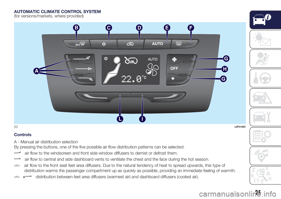
Controls
A - Manual air distribution selection
By pressing the buttons, one of the five possible air flow distribution patterns can be selected:
air flow to the windscreen and front side window diffusers to demist or defrost them.
air flow to central and side dashboard vents to ventilate the chest and the face during the hot season.
air flow to the front seat feet area diffusers. Due to the natural tendency of heat to spread upwards, this type of
distribution warms the passenger compartment up as quickly as possible, providing an immediate feeling of warmth.
+distribution between feet area diffusers (warmest air) and dashboard diffusers (coolest air).
23L0F0129C
25
Page 29 of 200

ELECTRIC WINDOWS
20)
These operate when the ignition key is
turned to MAR-ON and for about
three minutes after the ignition key is
turned to STOP or removed unless one
of the front doors is opened.
Driver side front door controls
All windows can be controlled from the
driver side door panel fig. 24.
A: front left window opening/closing;
“continuous automatic” operation
during window opening/closing stage;
B: opening/closing front right window;
"continuous automatic" operation
during window opening/closing stage
(for versions/markets, where provided)
C: enabling/disabling of rear door
electric window controls;D: rear left window opening/closing (for
versions/markets where provided);
“continuous automatic” operation
during window opening/closing stage;
E: opening/closing rear right window
(for versions/markets, where provided);
"continuous automatic" operation
during window opening/closing stage.
Use the buttons to open/close the
desired window.
When one of the two buttons is
pressed briefly, the window moves in
stages; if the button is held down,
"continuous automatic" operation is
activated both for closing and opening
(only with ignition key at MAR).
Anti-crush safety device
(for versions/markets, where provided)
11)
This safety system detects the
presence of an obstacle during the
window closing travel and intervenes by
stopping and reversing the window
travel, depending on its position.
The anti-pinch function is active both
during manual and automatic operation
of the electric windows. Following the
intervention of the anti-pinch system,
the window travel is immediately
interrupted and subsequently reversed
until the lower end of travel is reached.
The window cannot be operated in
any way during this time.Electric window system
initialisation
If power supply is interrupted when the
window is moving, the electric window
automatic operation must be
reinitialised.
The initialisation procedure must be
carried out with the doors closed and
for each door, as described below:
fully close the window to be
initialised, with manual operation;
after the window has reached the
upper end of travel, hold the up button
pressed for at least one second.
WARNING
20)Improper use of the electric windows
can be dangerous. Before and during
operation, always check that nobody is
exposed to the risk of being injured either
directly by the moving window or through
objects getting caught or hit by it. When
leaving the vehicle, always remove the
ignition key to avoid the risk of injury for
people still on board due to accidental
operation of the electric windows.
WARNING
11)The system conforms to the
2000/4/EC standard concerning the safety
of passengers leaning out of the passenger
compartment.
24L0F0162C
27
Page 30 of 200
ELECTRIC SUN
ROOF
(for versions/markets, where provided)
21)12)
The large electric sun roof comprises
two glass panels; the front one is
mobile and the rear one fixed. These
are equipped with two sun blinds (front
and rear) that can be moved manually.
With the sun roof closed, the blinds can
be placed in any position.
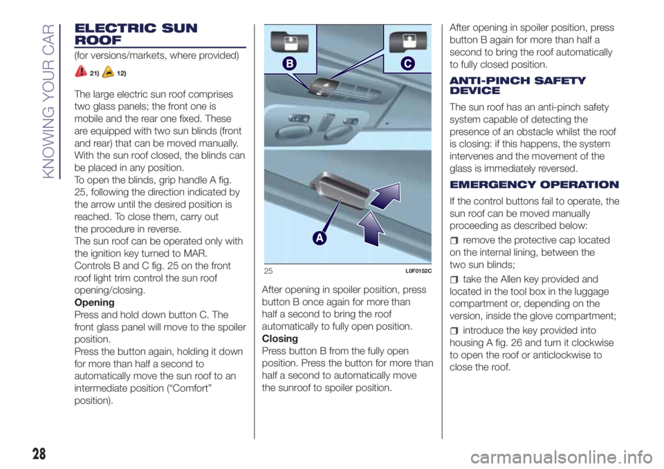
To open the blinds, grip handle A fig.
25, following the direction indicated by
the arrow until the desired position is
reached. To close them, carry out
the procedure in reverse.
The sun roof can be operated only with
the ignition key turned to MAR.
Controls B and C fig. 25 on the front
roof light trim control the sun roof
opening/closing.
Opening
Press and hold down button C. The
front glass panel will move to the spoiler
position.
Press the button again, holding it down
for more than half a second to
automatically move the sun roof to an
intermediate position (“Comfort”
position).After opening in spoiler position, press
button B once again for more than
half a second to bring the roof
automatically to fully open position.
Closing
Press button B from the fully open
position. Press the button for more than
half a second to automatically move
the sunroof to spoiler position.After opening in spoiler position, press
button B again for more than half a
second to bring the roof automatically
to fully closed position.
ANTI-PINCH SAFETY
DEVICE
The sun roof has an anti-pinch safety
system capable of detecting the
presence of an obstacle whilst the roof
is closing: if this happens, the system
intervenes and the movement of the
glass is immediately reversed.
EMERGENCY OPERATION
If the control buttons fail to operate, the
sun roof can be moved manually
proceeding as described below:
remove the protective cap located
on the internal lining, between the
two sun blinds;
take the Allen key provided and
located in the tool box in the luggage
compartment or, depending on the
version, inside the glove compartment;
introduce the key provided into
housing A fig. 26 and turn it clockwise
to open the roof or anticlockwise to
close the roof.
25L0F0152C
28
KNOWING YOUR CAR
Page 43 of 200
DISPLAY
Multifunctional display
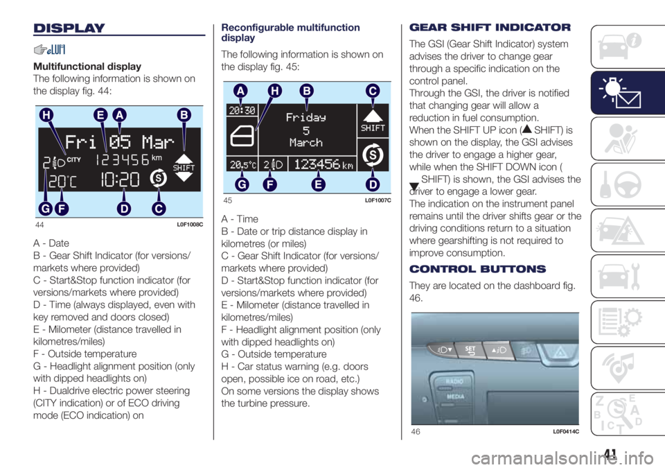
The following information is shown on
the display fig. 44:
A - Date
B - Gear Shift Indicator (for versions/
markets where provided)
C - Start&Stop function indicator (for
versions/markets where provided)
D - Time (always displayed, even with
key removed and doors closed)
E - Milometer (distance travelled in
kilometres/miles)
F - Outside temperature
G - Headlight alignment position (only
with dipped headlights on)
H - Dualdrive electric power steering
(CITY indication) or of ECO driving
mode (ECO indication) onReconfigurable multifunction
display
The following information is shown on
the display fig. 45:
A-Time
B - Date or trip distance display in
kilometres (or miles)
C - Gear Shift Indicator (for versions/
markets where provided)
D - Start&Stop function indicator (for
versions/markets where provided)
E - Milometer (distance travelled in
kilometres/miles)
F - Headlight alignment position (only
with dipped headlights on)
G - Outside temperature
H - Car status warning (e.g. doors
open, possible ice on road, etc.)
On some versions the display shows
the turbine pressure.GEAR SHIFT INDICATOR
The GSI (Gear Shift Indicator) system
advises the driver to change gear
through a specific indication on the
control panel.
Through the GSI, the driver is notified
that changing gear will allow a
reduction in fuel consumption.
When the SHIFT UP icon (
SHIFT) is
shown on the display, the GSI advises
the driver to engage a higher gear,
while when the SHIFT DOWN icon (
SHIFT) is shown, the GSI advises the
driver to engage a lower gear.
The indication on the instrument panel
remains until the driver shifts gear or the
driving conditions return to a situation
where gearshifting is not required to
improve consumption.
CONTROL BUTTONS
They are located on the dashboard fig.
46.
44L0F1008C
45L0F1007C
46L0F0414C
41
Page 44 of 200
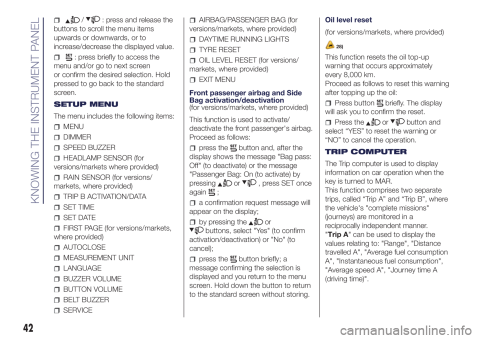
/: press and release the
buttons to scroll the menu items
upwards or downwards, or to
increase/decrease the displayed value.
: press briefly to access the
menu and/or go to next screen
or confirm the desired selection. Hold
pressed to go back to the standard
screen.
SETUP MENU
The menu includes the following items:
MENU
DIMMER
SPEED BUZZER
HEADLAMP SENSOR (for
versions/markets where provided)
RAIN SENSOR (for versions/
markets, where provided)
TRIP B ACTIVATION/DATA
SET TIME
SET DATE
FIRST PAGE (for versions/markets,
where provided)
AUTOCLOSE
MEASUREMENT UNIT
LANGUAGE
BUZZER VOLUME
BUTTON VOLUME
BELT BUZZER
SERVICE
AIRBAG/PASSENGER BAG (for
versions/markets, where provided)
DAYTIME RUNNING LIGHTS
TYRE RESET
OIL LEVEL RESET (for versions/
markets, where provided)
EXIT MENU
Front passenger airbag and Side
Bag activation/deactivation
(for versions/markets, where provided)
This function is used to activate/
deactivate the front passenger's airbag.
Proceed as follows:
press thebutton and, after the
display shows the message "Bag pass:
Off" (to deactivate) or the message
"Passenger Bag: On (to activate) by
pressing
or, press SET once
again
;
a confirmation request message will
appear on the display;
by pressing theor
buttons, select "Yes" (to confirm
activation/deactivation) or "No" (to
cancel);
press thebutton briefly; a
message confirming the selection is
displayed and you return to the menu
screen. Hold down the button to return
to the standard screen without storing.Oil level reset
(for versions/markets, where provided)
28)
This function resets the oil top-up
warning that occurs approximately
every 8,000 km.
Proceed as follows to reset this warning
after topping up the oil:
Press buttonbriefly. The display
will ask you to confirm the reset.
Press theorbutton and
select “YES” to reset the warning or
“NO” to cancel the operation.
TRIP COMPUTER
The Trip computer is used to display
information on car operation when the
key is turned to MAR.
This function comprises two separate
trips, called “Trip A” and “Trip B”, where
the vehicle's "complete missions"
(journeys) are monitored in a
reciprocally independent manner.
"Trip A" can be used to display the
values relating to: "Range", "Distance
travelled A", "Average fuel consumption
A", "Instantaneous fuel consumption",
"Average speed A", "Journey time A
(driving time)".
42
KNOWING THE INSTRUMENT PANEL
Page 176 of 200
SWITCHING THE SYSTEM
ON/OFF
The system is switched on/off by
pressing the
(ON/OFF) button/knob.
Turn the button/knob clockwise to
increase the radio volume or
anticlockwise to decrease it.
The system is equipped with the
following tuners: AM, FM and DAB (for
versions/markets, where provided).
RADIO MODE
Press the RADIO button on the front
panel to activate radio mode.
After the desired radio station is
selected, the following information is
shown on the display:
At the top: the list of radio stations
stored (preset) is displayed; the station
currently playing is highlighted.
In the middle: display of the name of
the current radio station and the
buttons for selecting the previous or
next radio station.
At the bottom: display of the following
buttons:
"Browse": list of the radio stations
available;
"AM/FM", "AM/DAB", "FM/DAB":
selection of the desired frequency band
(button reconfigurable according to
the band selected: AM, FM or DAB);
"Tune" : manual radio station tuning
(not available for DAB radios);
"Info": additional information on the
source being listened to;
"Audio": access to the "Audio
settings" screen.
Radio station selection
To search for the desired radio station
press buttons
oron the display
or use the steering wheel controls.
Previous/next radio station search
Briefly press buttons
oron
the display: when the button is released
the previous or the next radio station
is displayed.
Previous/next radio station fast
search
Hold down buttons
oron the
display to start fast search: when the
button is released, the first tunable
radio station can be heard.
Audio menu
To access the "Audio" menu press the
Audio" button located at the bottom
of the display.
The following adjustments can be
carried out using the "Audio" menu:
"Equaliser" (for versions/markets,
where provided);
"Balance/Fader" (left/right and
front/rear audio balance adjustment);
"Speed/Volume" (speed-dependent
automatic volume control);
"Loudness" (for versions/markets,
where provided);
"Auto-On Radio";
"Radio Off Delay".
To exit the "Audio" menu, press the
/Done button.
MEDIA MODE
Audio source selection
Press the "Source" button to select the
desired audio source among those
available: AUX, USB, iPod or
Bluetooth®.
NOTE Applications used on portable
devices may be not compatible with the
Uconnect™system
Track change
Briefly press the
button or turn the
BROWSE ENTER button/knob
clockwise to play the next track or
briefly press the
button or turn the
BROWSE ENTER button/knob
anticlockwise to return to the beginning
of the selected track or to the beginning
of the previous track if it has been
played for less than 3 seconds.
174
MULTIMEDIA
Page 178 of 200
NOTE After updating the phone
software, for proper operation, it is
recommended to remove the phone
from the list of devices linked to the
radio, delete the previous system
pairing also from the list ofBluetooth®
devices on the phone and make a
new pairing.
AUX SOURCE
To activate AUX mode, insert an
appropriate device in the AUX socket
on the vehicle.
When a device WITH AUX output is
inserted the system starts reproducing
the AUX source connected, if it is
already being played.
Adjust the volume using the
button/
knob on the front panel or using the
volume adjustment control on the
connected device.
For the "Audio source selection"
function, see the "Media mode"
chapter.
IMPORTANT NOTES
The functions of the device connected
with the AUX socket are directly
managed by the device itself: it is not
possible to change track/folder/playlist
or control playing start/end/pause
with the controls on the front panel or
on the steering wheel.Do not leave the cable of your portable
player connected to the AUX socket
after disconnection, to avoid possible
hiss from the speakers.
USB/iPod SOURCE
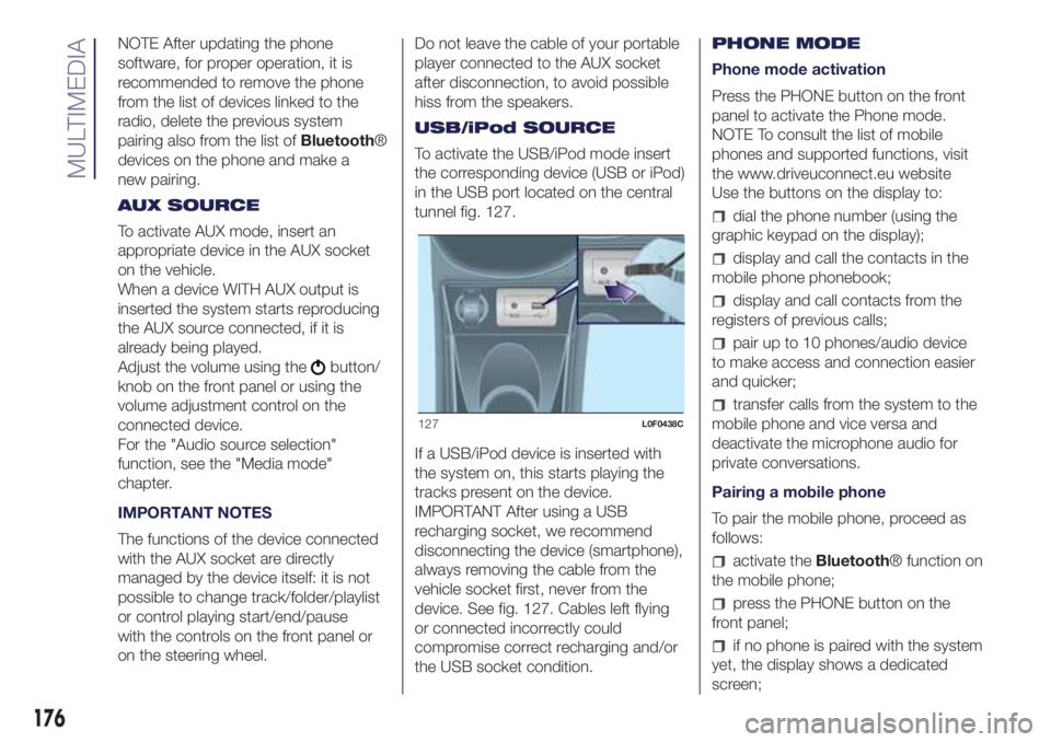
To activate the USB/iPod mode insert
the corresponding device (USB or iPod)
in the USB port located on the central
tunnel fig. 127.
If a USB/iPod device is inserted with
the system on, this starts playing the
tracks present on the device.
IMPORTANT After using a USB
recharging socket, we recommend
disconnecting the device (smartphone),
always removing the cable from the
vehicle socket first, never from the
device. See fig. 127. Cables left flying
or connected incorrectly could
compromise correct recharging and/or
the USB socket condition.PHONE MODE
Phone mode activation
Press the PHONE button on the front
panel to activate the Phone mode.
NOTE To consult the list of mobile
phones and supported functions, visit
the www.driveuconnect.eu website
Use the buttons on the display to:
dial the phone number (using the
graphic keypad on the display);
display and call the contacts in the
mobile phone phonebook;
display and call contacts from the
registers of previous calls;
pair up to 10 phones/audio device
to make access and connection easier
and quicker;
transfer calls from the system to the
mobile phone and vice versa and
deactivate the microphone audio for
private conversations.
Pairing a mobile phone
To pair the mobile phone, proceed as
follows:
activate theBluetooth® function on
the mobile phone;
press the PHONE button on the
front panel;
if no phone is paired with the system
yet, the display shows a dedicated
screen;
127L0F0438C
176
MULTIMEDIA