check engine light LAND ROVER DEFENDER 1999 Workshop Manual
[x] Cancel search | Manufacturer: LAND ROVER, Model Year: 1999, Model line: DEFENDER, Model: LAND ROVER DEFENDER 1999Pages: 667, PDF Size: 8.76 MB
Page 127 of 667
12ENGINE
2
REPAIR
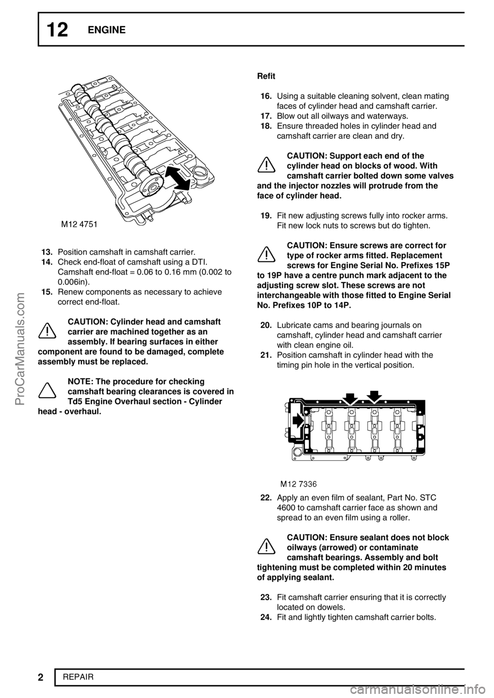
13.Position camshaft in camshaft carrier.
14.Check end-float of camshaft using a DTI.
Camshaft end-float = 0.06 to 0.16 mm (0.002 to
0.006in).
15.Renew components as necessary to achieve
correct end-float.
CAUTION: Cylinder head and camshaft
carrier are machined together as an
assembly. If bearing surfaces in either
component are found to be damaged, complete
assembly must be replaced.
NOTE: The procedure for checking
camshaft bearing clearances is covered in
Td5 Engine Overhaul section - Cylinder
head - overhaul.Refit
16.Using a suitable cleaning solvent, clean mating
faces of cylinder head and camshaft carrier.
17.Blow out all oilways and waterways.
18.Ensure threaded holes in cylinder head and
camshaft carrier are clean and dry.
CAUTION: Support each end of the
cylinder head on blocks of wood. With
camshaft carrier bolted down some valves
and the injector nozzles will protrude from the
face of cylinder head.
19.Fit new adjusting screws fully into rocker arms.
Fit new lock nuts to screws but do tighten.
CAUTION: Ensure screws are correct for
type of rocker arms fitted. Replacement
screws for Engine Serial No. Prefixes 15P
to 19P have a centre punch mark adjacent to the
adjusting screw slot. These screws are not
interchangeable with those fitted to Engine Serial
No. Prefixes 10P to 14P.
20.Lubricate cams and bearing journals on
camshaft, cylinder head and camshaft carrier
with clean engine oil.
21.Position camshaft in cylinder head with the
timing pin hole in the vertical position.
22.Apply an even film of sealant, Part No. STC
4600 to camshaft carrier face as shown and
spread to an even film using a roller.
CAUTION: Ensure sealant does not block
oilways (arrowed) or contaminate
camshaft bearings. Assembly and bolt
tightening must be completed within 20 minutes
of applying sealant.
23.Fit camshaft carrier ensuring that it is correctly
located on dowels.
24.Fit and lightly tighten camshaft carrier bolts.
ProCarManuals.com
Page 135 of 667
12ENGINE
10
REPAIR Refit
39.Clean mating faces of cylinder head and cylinder
block.
40.Check cylinder head for warping, across centre
and from corner to corner:
Maximum warp = 0.10 mm (0.004 in)
CAUTION: Cylinder heads may not be
refaced, replace cylinder head assembly if
warping exceeds figure given.
41.Ensure coolant and oil passages are clean.
42.Clean dowel holes and fit new dowels.
43.Fit new cylinder head gasket of the correct
thickness with the word’TOP’uppermost.
44.Using assistance, fit cylinder head and locate on
to dowels.
45.Carefully enter new cylinder head bolts together
with their captive washers,DO NOT DROP.
Lightly tighten bolts.
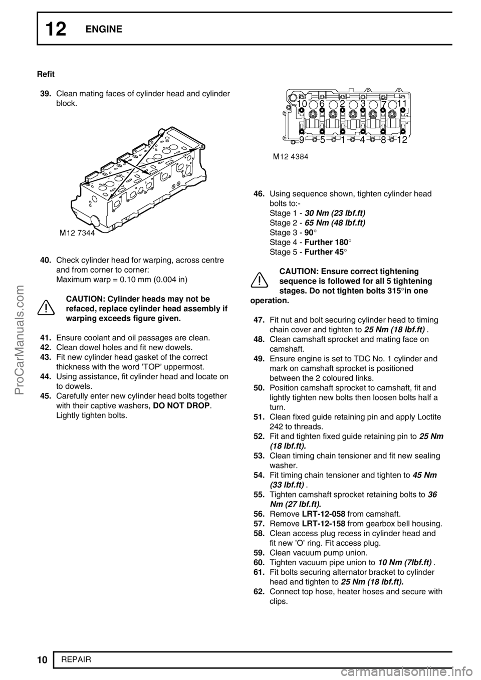
46.Using sequence shown, tighten cylinder head
bolts to:-
Stage 1 -30 Nm (23 lbf.ft)
Stage 2 -65 Nm (48 lbf.ft)
Stage 3 -90°
Stage 4 -Further 180°
Stage 5 -Further 45°
CAUTION: Ensure correct tightening
sequence is followed for all 5 tightening
stages. Do not tighten bolts 315°in one
operation.
47.Fit nut and bolt securing cylinder head to timing
chain cover and tighten to25 Nm (18 lbf.ft).
48.Clean camshaft sprocket and mating face on
camshaft.
49.Ensure engine is set to TDC No. 1 cylinder and
mark on camshaft sprocket is positioned
between the 2 coloured links.
50.Position camshaft sprocket to camshaft, fit and
lightly tighten new bolts then loosen bolts half a
turn.
51.Clean fixed guide retaining pin and apply Loctite
242 to threads.
52.Fit and tighten fixed guide retaining pin to25 Nm
(18 lbf.ft).
53.Clean timing chain tensioner and fit new sealing
washer.
54.Fit timing chain tensioner and tighten to45 Nm
(33 lbf.ft).
55.Tighten camshaft sprocket retaining bolts to36
Nm (27 lbf.ft).
56.RemoveLRT-12-058from camshaft.
57.RemoveLRT-12-158from gearbox bell housing.
58.Clean access plug recess in cylinder head and
fit new’O’ring. Fit access plug.
59.Clean vacuum pump union.
60.Tighten vacuum pipe union to10 Nm (7lbf.ft).
61.Fit bolts securing alternator bracket to cylinder
head and tighten to25 Nm (18 lbf.ft).
62.Connect top hose, heater hoses and secure with
clips.
ProCarManuals.com
Page 164 of 667
ENGINE
5
OVERHAUL Refit
1.Thoroughly clean cylinder block and cylinder
head mating faces.
2.Ensure coolant and oil passageways are clear
and bolt holes are clean and dry.
3.Ensure locating dowel holes in cylinder block are
clean and dry.
4.Fit new plastic locating dowels in cylinder block.
5.Fit new cylinder head gasket of the correct
thickness with the word’TOP’uppermost.
CAUTION: Gasket must be fitted dry.
6.Ensure that camshaft timing pinLRT-12-158is
still in position and using assistance, fit cylinder
head.
7.Carefully enter new cylinder head bolts together
with their captive washers,DO NOT DROP.
Lightly tighten bolts.
CAUTION: Cylinder head bolts are
pre-lubricated and do not require
additional lubrication.
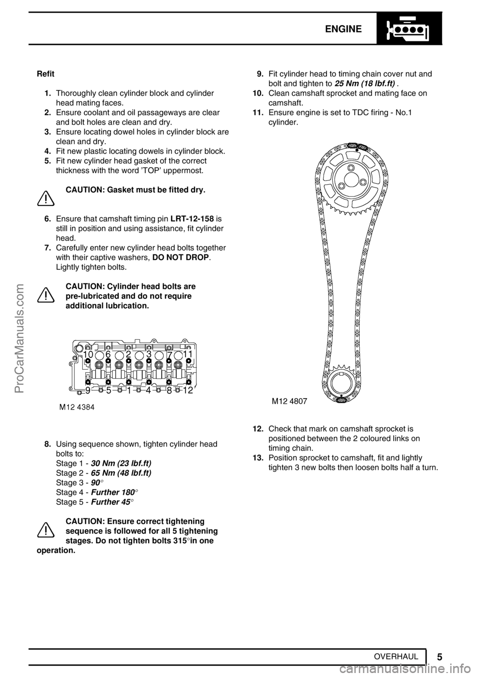
8.Using sequence shown, tighten cylinder head
bolts to:
Stage 1 -30 Nm (23 lbf.ft)
Stage 2 -65 Nm (48 lbf.ft)
Stage 3 -90
°
Stage 4 -Further 180°
Stage 5 -Further 45°
CAUTION: Ensure correct tightening
sequence is followed for all 5 tightening
stages. Do not tighten bolts 315°in one
operation.9.Fit cylinder head to timing chain cover nut and
bolt and tighten to25 Nm (18 lbf.ft).
10.Clean camshaft sprocket and mating face on
camshaft.
11.Ensure engine is set to TDC firing - No.1
cylinder.
12.Check that mark on camshaft sprocket is
positioned between the 2 coloured links on
timing chain.
13.Position sprocket to camshaft, fit and lightly
tighten 3 new bolts then loosen bolts half a turn.
ProCarManuals.com
Page 184 of 667
ENGINE
25
OVERHAUL
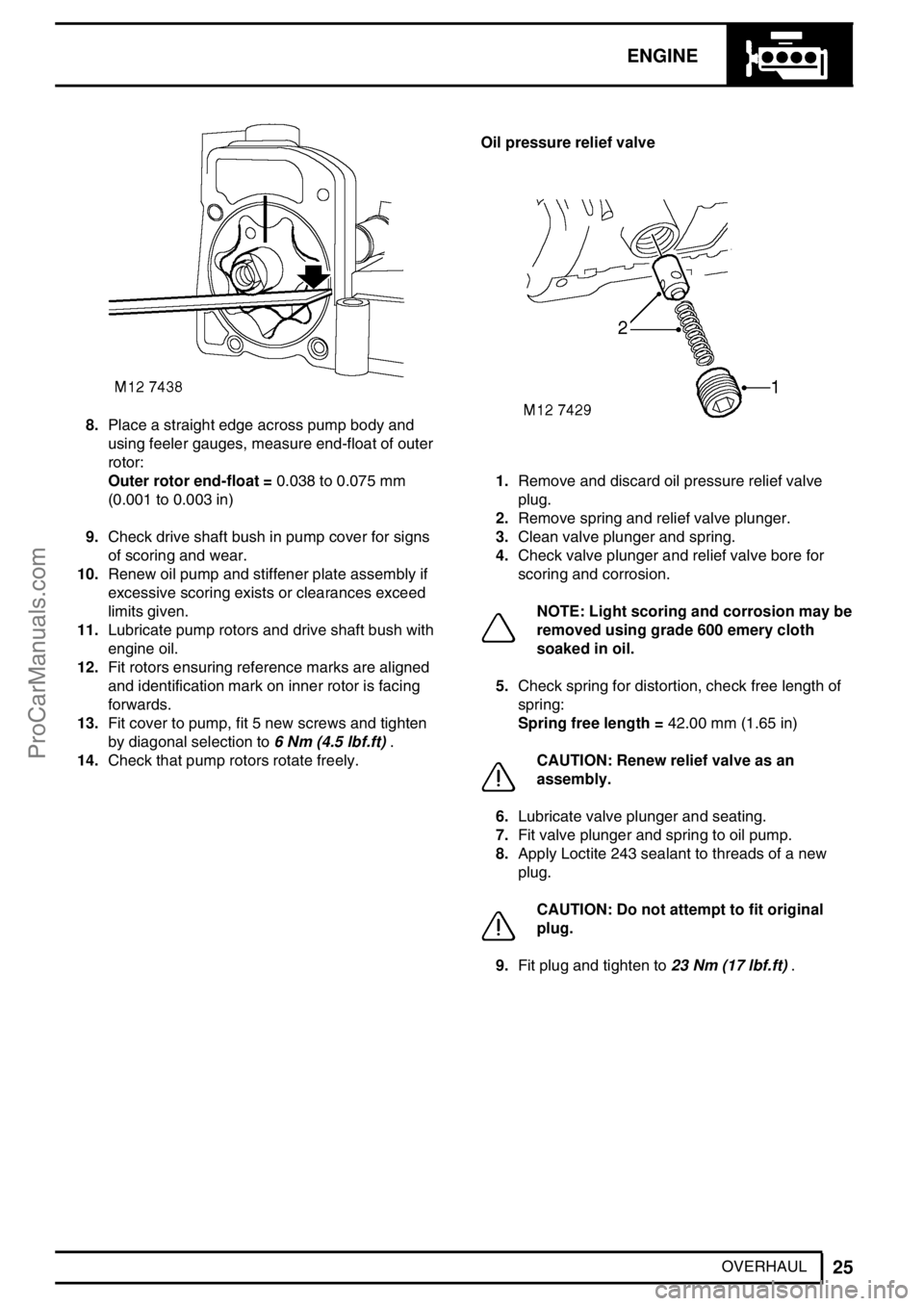
8.Place a straight edge across pump body and
using feeler gauges, measure end-float of outer
rotor:
Outer rotor end-float =0.038 to 0.075 mm
(0.001 to 0.003 in)
9.Check drive shaft bush in pump cover for signs
of scoring and wear.
10.Renew oil pump and stiffener plate assembly if
excessive scoring exists or clearances exceed
limits given.
11.Lubricate pump rotors and drive shaft bush with
engine oil.
12.Fit rotors ensuring reference marks are aligned
and identification mark on inner rotor is facing
forwards.
13.Fit cover to pump, fit 5 new screws and tighten
by diagonal selection to6 Nm (4.5 lbf.ft).
14.Check that pump rotors rotate freely.Oil pressure relief valve
1.Remove and discard oil pressure relief valve
plug.
2.Remove spring and relief valve plunger.
3.Clean valve plunger and spring.
4.Check valve plunger and relief valve bore for
scoring and corrosion.
NOTE: Light scoring and corrosion may be
removed using grade 600 emery cloth
soaked in oil.
5.Check spring for distortion, check free length of
spring:
Spring free length =42.00 mm (1.65 in)
CAUTION: Renew relief valve as an
assembly.
6.Lubricate valve plunger and seating.
7.Fit valve plunger and spring to oil pump.
8.Apply Loctite 243 sealant to threads of a new
plug.
CAUTION: Do not attempt to fit original
plug.
9.Fit plug and tighten to23 Nm (17 lbf.ft).
ProCarManuals.com
Page 187 of 667
12ENGINE
28
OVERHAUL Inspection
1.Clean all components.
2.Check condition of timing chain running surfaces
on adjustable and fixed guides.
CAUTION: Adjustable guide fitted to
Engine Serial No. Prefixes 15P to 19P may
be fitted to Engine Serial No. Prefixes 10P
to 14P provided that timing chain tensioner having
a YELLOW colour coded body is also fitted.
3.Check timing chains and sprockets for signs of
wear.
CAUTION: Timing chains and sprockets
fitted to Engine Serial No. Prefixes 15P to
19P may be fitted to Engine Serial No.
Prefixes 10P to 14P as an assembly only, oil pump
sprockets are interchangeable. Timing chains
fitted to Engine Serial No. Prefixes 15P to 19P
have BRONZE coloured timing links.
4.Check that drilling in timing chain lubrication jet
is clear.
5.Clean oil seal recess in timing cover and oil seal
running surface on crankshaft.
6.Remove all traces of sealant from mating faces
of timing cover and cylinder block using suitable
solvent.
CAUTION: Do not use metal scrapers.
7.Ensure bolt and dowel holes are clean and dry.
8.Clean oil pump sprocket bolt threads.Refit
1.Fit timing chain lubrication jet.
2.Fit bolt securing lubrication jet and tighten to10
Nm (7 lbf.ft).
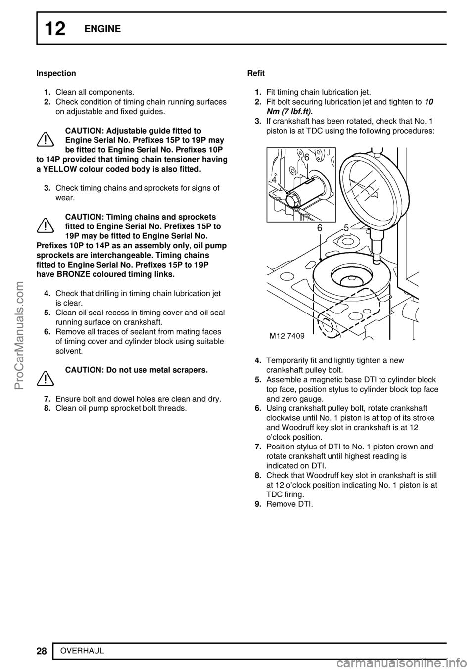
3.If crankshaft has been rotated, check that No. 1
piston is at TDC using the following procedures:
4.Temporarily fit and lightly tighten a new
crankshaft pulley bolt.
5.Assemble a magnetic base DTI to cylinder block
top face, position stylus to cylinder block top face
and zero gauge.
6.Using crankshaft pulley bolt, rotate crankshaft
clockwise until No. 1 piston is at top of its stroke
and Woodruff key slot in crankshaft is at 12
o’clock position.
7.Position stylus of DTI to No. 1 piston crown and
rotate crankshaft until highest reading is
indicated on DTI.
8.Check that Woodruff key slot in crankshaft is still
at 12 o’clock position indicating No. 1 piston is at
TDC firing.
9.Remove DTI.
ProCarManuals.com
Page 190 of 667
ENGINE
31
OVERHAUL 8.Remove and discard big-end bearing shell from
connecting rod.
CAUTION: Engine Serial No. Prefixes 10P
to 14P:- The’sputter type’connecting rod
bearings fitted to these engines, identified
by them having a slightly darker colour than the
bearing cap shells should be replaced with the
’plain type’bearing shells fitted to Engine Serial
No. Prefixes 15P to 19P.
9.Repeat above procedures for remaining big-end
bearings.
CAUTION: Keep bearing caps in their fitted
order.
Inspection
NOTE: If crankshaft is to be removed,
big-end bearing journals should be
checked when crankshaft is inspected.
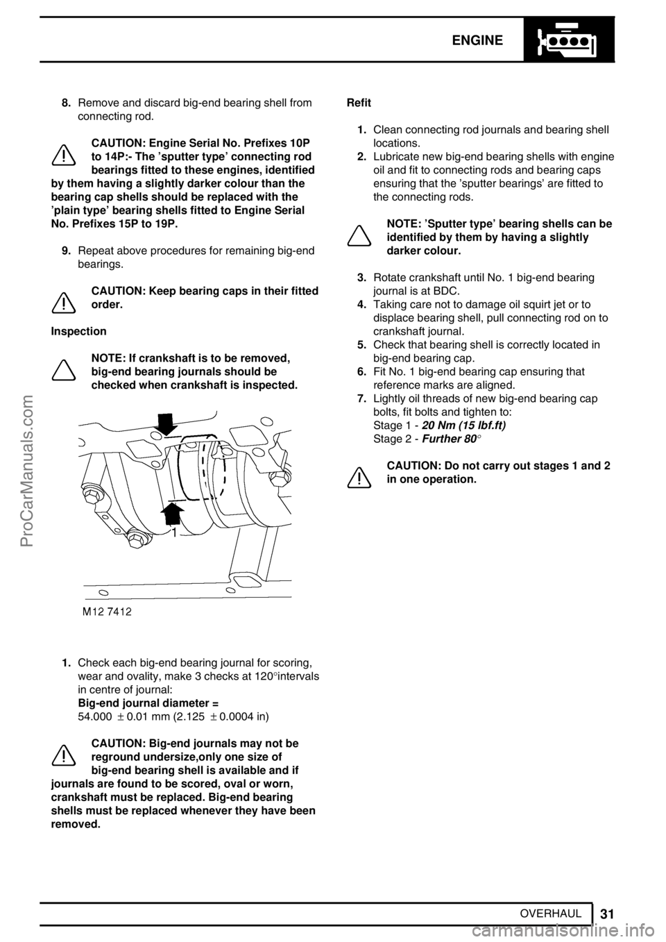
1.Check each big-end bearing journal for scoring,
wear and ovality, make 3 checks at 120°intervals
in centre of journal:
Big-end journal diameter =
54.000±0.01 mm (2.125±0.0004 in)
CAUTION: Big-end journals may not be
reground undersize,only one size of
big-end bearing shell is available and if
journals are found to be scored, oval or worn,
crankshaft must be replaced. Big-end bearing
shells must be replaced whenever they have been
removed.Refit
1.Clean connecting rod journals and bearing shell
locations.
2.Lubricate new big-end bearing shells with engine
oil and fit to connecting rods and bearing caps
ensuring that the’sputter bearings’are fitted to
the connecting rods.
NOTE:’Sputter type’bearing shells can be
identified by them by having a slightly
darker colour.
3.Rotate crankshaft until No. 1 big-end bearing
journal is at BDC.
4.Taking care not to damage oil squirt jet or to
displace bearing shell, pull connecting rod on to
crankshaft journal.
5.Check that bearing shell is correctly located in
big-end bearing cap.
6.Fit No. 1 big-end bearing cap ensuring that
reference marks are aligned.
7.Lightly oil threads of new big-end bearing cap
bolts, fit bolts and tighten to:
Stage 1 -20 Nm (15 lbf.ft)
Stage 2 -Further 80
°
CAUTION: Do not carry out stages 1 and 2
in one operation.
ProCarManuals.com
Page 197 of 667
12ENGINE
38
OVERHAUL Crankshaft spigot bush
1.Check crankshaft spigot bush for wear, replace if
necessary using the following procedures:
2.Secure crankshaft in a suitably padded vice.
3.Tap a thread in spigot bush to accommodate a
suitable impulse extractor.
4.Fit impulse extractor to spigot bush.
5.Remove spigot bush.
6.Clean spigot bush recess in crankshaft.
7.Fit new spigot bush to crankshaft using a
suitable mandrel.
Crankshaft - Refit
1.Fit oil squirt jets, fit Torx screws and tighten to8
Nm (6 lbf.ft).
2.Lubricate new, grooved, main bearing shells with
engine oil and fit to cylinder block.
3.Lubricate new thrust washers with engine oil and
fit, grooved side facing outwards, to recess in
each side of cylinder block No. 3 main bearing.
4.Lubricate crankshaft journals with engine oil and
using assistance, position crankshaft in cylinder
block.
5.Lubricate new, plain, main bearing shells with
engine oil and fit to main bearing caps.
6.Fit main bearing caps in their original fitted
positions ensuring that reference marks are
aligned.
7.Fit and lightly tighten new main bearing cap
bolts.
CAUTION: Do not lubricate bolt threads.
8.Starting with No. 3 main bearing cap and
working outwards, tighten main bearing cap bolts
to:
Stage 1 -33 Nm (24 lbf.ft)
Stage 2 -Further 90
°
CAUTION: Do not carry out stages 1 and 2
in one operation.
9.Check that crankshaft rotates smoothly.
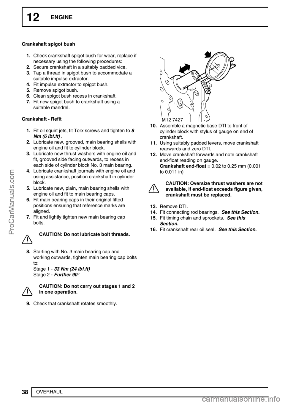
10.Assemble a magnetic base DTI to front of
cylinder block with stylus of gauge on end of
crankshaft.
11.Using suitably padded levers, move crankshaft
rearwards and zero DTI.
12.Move crankshaft forwards and note crankshaft
end-float reading on gauge.
Crankshaft end-float =0.02 to 0.25 mm (0.001
to 0.011 in)
CAUTION: Oversize thrust washers are not
available, if end-float exceeds figure given,
crankshaft must be replaced.
13.Remove DTI.
14.Fit connecting rod bearings.See this Section.
15.Fit timing chain and sprockets.See this
Section.
16.Fit crankshaft rear oil seal.See this Section.
ProCarManuals.com
Page 510 of 667
PANEL REPAIRS
1
INFORMATION BODY REPAIRS
Body shells are of riveted, bolted and welded
construction and are bolted to the chassis frame.
It is essential that design dimensions and strength are
restored in accident rectification. It is important that
neither structural weakness nor excessive local
stiffness are introduced into the vehicle during body or
chassis repair.
Repairs usually involve a combination of operations
ranging from straightening procedures to renewal of
either individual panels or panel assemblies. The
repairer will determine the repair method and this
decision will take into account a balance of economics
between labour and material costs and the availability
of repair facilities in both equipment and skills. It may
also involve considerations of vehicles down-time,
replacement vehicle availability and repair turn-around
time.
It is expected that a repairer will select the best and
most economic repair method possible, making use of
the facilities available. The instructions given are
intended to assist a skilled body repairer by expanding
approved procedures for panel replacement with the
objective of restoring the vehicle to a safe running
condition and effecting a repair which is visually
acceptable and which, even to the experienced eye,
does not advertise the fact that it has been damaged.
This does not necessarily mean that the repaired
vehicle will be identical in all respects with original
factory build. Repair facilities cannot always duplicate
methods of construction used during production.
The panel repairs shown in this section are all based
on a 110 Station Wagon. Therefore all illustrations
and text relate only to this model. Although certain
areas of the vehicle, such as the front end, are
relevant to all models.
Operations covered in this Manual do not include
reference to testing the vehicle after repair. It is
essential that work is inspected and suspension
geometry checked after completion and if necessary a
road test of the vehicle is carried out, particularly
where safety related items are concerned.Where major units have been disconnected or
removed, it is necessary to ensure that fluid levels are
checked and topped up when necessary. It is also
necessary to ensure that the repaired vehicle is in a
roadworthy condition in respect of tyre pressures,
lights, washer fluid etc.
Body repairs often involve the removal of mechanical
and electrical units as well as associated wiring.
Where this is necessary use the relevant section in
this manual.
Taking into consideration the differences in body
styles, steering and suspension systems as well as
engine and suspension layouts, the location of the
following components as applicable to a particular
vehicle is critical:
Front suspension upper damper
mountings.
Front suspension or sub frame mountings.
Engine mountings on RH and LH chassis
longitudinals.
Rear suspension upper damper mountings.
Rear suspension mountings or lower
pivots.
Steering rack mountings.
Additional points which can be used to check
alignment and assembly are:
Inner holes in crossmember - side - main
floor.
Holes in valance front assembly.
Body to chassis mounting holes.
Holes in rear floor.
Holes in rear lower panels or extension
rear floor.
Fuel tank mountings.
Apertures for windscreen, backlight, bonnet and doors
can be checked by offering up an undamaged
component as a gauge and also by measuring known
dimensions.See BODY DIMENSIONS section.
ProCarManuals.com