dimensions LAND ROVER DEFENDER 1999 Workshop Manual
[x] Cancel search | Manufacturer: LAND ROVER, Model Year: 1999, Model line: DEFENDER, Model: LAND ROVER DEFENDER 1999Pages: 667, PDF Size: 8.76 MB
Page 6 of 667
01 - INTRODUCTION
CONTENTS
Page
INFORMATION
INTRODUCTION 1..................................................................................................
DIMENSIONS 1.......................................................................................................
REFERENCES 1.....................................................................................................
REPAIRS AND REPLACEMENTS 1.......................................................................
POISONOUS SUBSTANCES 1..............................................................................
FUEL HANDLING PRECAUTIONS 2......................................................................
SYNTHETIC RUBBER 3.........................................................................................
RECOMMENDED SEALANTS 3.............................................................................
USED ENGINE OIL 3..............................................................................................
ACCESSORIES AND CONVERSIONS 4...............................................................
WHEELS AND TYRES 4.........................................................................................
STEAM CLEANING 4..............................................................................................
SPECIFICATION 4..................................................................................................
SPECIAL SERVICE TOOLS 4................................................................................
JACKING 5..............................................................................................................
HYDRAULIC VEHICLE RAMP (FOUR POST) 6.....................................................
TWO POST VEHICLE RAMPS 6............................................................................
DYNAMOMETER TESTING 6................................................................................
TOWING 7..............................................................................................................
TRANSPORTING THE VEHICLE BY TRAILER 7..................................................
JUMP STARTING 8................................................................................................
ABBREVIATIONS AND SYMBOLS USED IN THIS MANUAL 9.............................
CROSS REFERENCE OF EMISSION SYSTEM TERMINOLOGY 10....................
VEHICLE IDENTIFICATION NUMBER (VIN) 11.....................................................
LOCATION OF IDENTIFICATION NUMBERS 12...................................................
FAULT DIAGNOSTIC EQUIPMENT 13..................................................................
READING THIS SUPPLEMENT 14........................................................................
ProCarManuals.com
Page 8 of 667
INTRODUCTION
1
INFORMATION INTRODUCTION
This Workshop Manual Supplement covers vehicles
from 1999 and 2002 model year onwards. The Body
Repair Manual has also been incorporated into this
supplement. Amendments and additional pages will
be issued, when necessary, to ensure that the
supplement covers latest models.
This Supplement is designed to assist skilled
technicians in the efficient repair and maintenance of
Land Rover Defender vehicles.
Individuals who undertake their own repairs should
have some skill and training, and limit repairs to
components which could not affect the safety of the
vehicle or its passengers. Any repairs required to
safety critical items such as steering, brakes,
suspension or supplementary restraint system should
be carried out by a Land Rover Dealer. Repairs to
such items should NEVER be attempted by untrained
individuals.
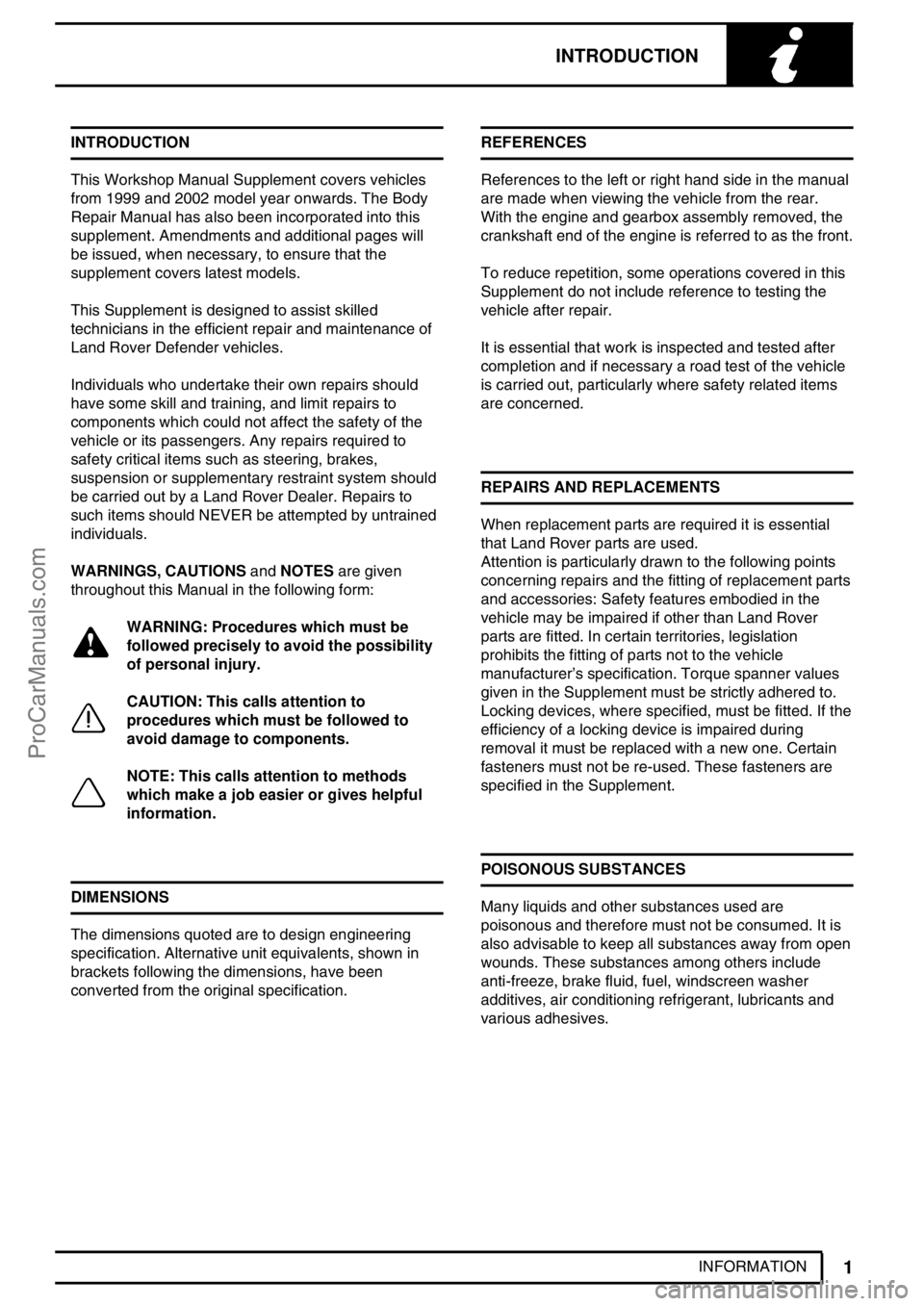
WARNINGS, CAUTIONSandNOTESare given
throughout this Manual in the following form:
WARNING: Procedures which must be
followed precisely to avoid the possibility
of personal injury.
CAUTION: This calls attention to
procedures which must be followed to
avoid damage to components.
NOTE: This calls attention to methods
which make a job easier or gives helpful
information.
DIMENSIONS
The dimensions quoted are to design engineering
specification. Alternative unit equivalents, shown in
brackets following the dimensions, have been
converted from the original specification.REFERENCES
References to the left or right hand side in the manual
are made when viewing the vehicle from the rear.
With the engine and gearbox assembly removed, the
crankshaft end of the engine is referred to as the front.
To reduce repetition, some operations covered in this
Supplement do not include reference to testing the
vehicle after repair.
It is essential that work is inspected and tested after
completion and if necessary a road test of the vehicle
is carried out, particularly where safety related items
are concerned.
REPAIRS AND REPLACEMENTS
When replacement parts are required it is essential
that Land Rover parts are used.
Attention is particularly drawn to the following points
concerning repairs and the fitting of replacement parts
and accessories: Safety features embodied in the
vehicle may be impaired if other than Land Rover
parts are fitted. In certain territories, legislation
prohibits the fitting of parts not to the vehicle
manufacturer’s specification. Torque spanner values
given in the Supplement must be strictly adhered to.
Locking devices, where specified, must be fitted. If the
efficiency of a locking device is impaired during
removal it must be replaced with a new one. Certain
fasteners must not be re-used. These fasteners are
specified in the Supplement.
POISONOUS SUBSTANCES
Many liquids and other substances used are
poisonous and therefore must not be consumed. It is
also advisable to keep all substances away from open
wounds. These substances among others include
anti-freeze, brake fluid, fuel, windscreen washer
additives, air conditioning refrigerant, lubricants and
various adhesives.
ProCarManuals.com
Page 22 of 667
04 - GENERAL SPECIFICATION DATA
CONTENTS
Page
INFORMATION
ENGINE - Td5 1......................................................................................................
FUEL SYSTEM - Td5 3...........................................................................................
COOLING SYSTEM - Td5 3....................................................................................
CLUTCH - Td5 3.....................................................................................................
TRANSMISSION - Td5 4.........................................................................................
STEERING 5...........................................................................................................
SUSPENSION 6......................................................................................................
ROAD SPRING DATA 6..........................................................................................
SHOCK ABSORBERS 7.........................................................................................
BRAKES 7...............................................................................................................
AIR CONDITIONING 8............................................................................................
WIPER MOTORS 8.................................................................................................
ELECTRICAL 8.......................................................................................................
BULBS9 .................................................................................................................
VEHICLE WEIGHTS AND PAYLOAD 10................................................................
TOWING WEIGHTS 11...........................................................................................
OFF-ROAD PERFORMANCE 11............................................................................
TYRE SIZE AND PRESSURES 12.........................................................................
WHEELS 12............................................................................................................
VEHICLE DIMENSIONS 13....................................................................................
ProCarManuals.com
Page 24 of 667
GENERAL SPECIFICATION DATA
1
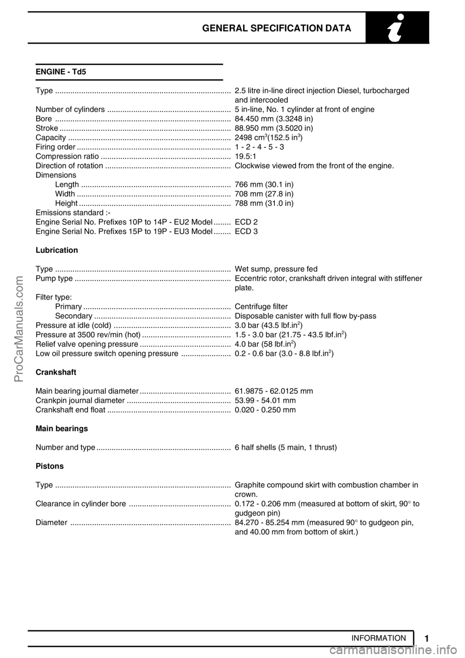
INFORMATION ENGINE - Td5
Type 2.5 litre in-line direct injection Diesel, turbocharged.................................................................................
and intercooled
Number of cylinders 5 in-line, No. 1 cylinder at front of engine.........................................................
Bore 84.450 mm (3.3248 in).................................................................................
Stroke 88.950 mm (3.5020 in)...............................................................................
Capacity 2498 cm
3(152.5 in3) ...........................................................................
Firing order 1 - 2 - 4 - 5 - 3.......................................................................
Compression ratio 19.5:1............................................................
Direction of rotation Clockwise viewed from the front of the engine...........................................................
Dimensions
Length 766 mm (30.1 in).....................................................................
Width 708 mm (27.8 in).......................................................................
Height 788 mm (31.0 in)......................................................................
Emissions standard :-
Engine Serial No. Prefixes 10P to 14P - EU2 Model ECD 2........
Engine Serial No. Prefixes 15P to 19P - EU3 Model ECD 3........
Lubrication
Type Wet sump, pressure fed.................................................................................
Pump type Eccentric rotor, crankshaft driven integral with stiffener........................................................................
plate.
Filter type:
Primary Centrifuge filter....................................................................
Secondary Disposable canister with full flow by-pass...............................................................
Pressure at idle (cold) 3.0 bar (43.5 lbf.in
2) ......................................................
Pressure at 3500 rev/min (hot) 1.5 - 3.0 bar (21.75 - 43.5 lbf.in2) .........................................
Relief valve opening pressure 4.0 bar (58 lbf.in2) ..........................................
Low oil pressure switch opening pressure 0.2 - 0.6 bar (3.0 - 8.8 lbf.in2) .......................
Crankshaft
Main bearing journal diameter 61.9875 - 62.0125 mm..........................................
Crankpin journal diameter 53.99 - 54.01 mm................................................
Crankshaft end float 0.020 - 0.250 mm.........................................................
Main bearings
Number and type 6 half shells (5 main, 1 thrust)..............................................................
Pistons
Type Graphite compound skirt with combustion chamber in.................................................................................
crown.
Clearance in cylinder bore 0.172 - 0.206 mm (measured at bottom of skirt, 90°to ...............................................
gudgeon pin)
Diameter 84.270 - 85.254 mm (measured 90°to gudgeon pin, ..........................................................................
and 40.00 mm from bottom of skirt.)
ProCarManuals.com
Page 36 of 667
GENERAL SPECIFICATION DATA
13
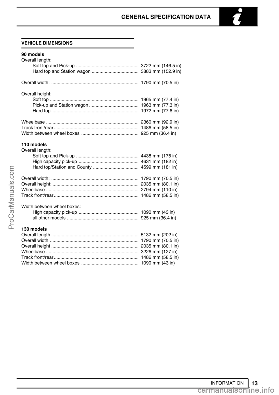
INFORMATION VEHICLE DIMENSIONS
90 models
Overall length:
Soft top and Pick-up 3722 mm (146.5 in)................................................
Hard top and Station wagon 3883 mm (152.9 in)....................................
Overall width: 1790 mm (70.5 in)...................................................................
Overall height:
Soft top 1965 mm (77.4 in)....................................................................
Pick-up and Station wagon 1963 mm (77.3 in)......................................
Hard top 1972 mm (77.6 in)...................................................................
Wheelbase 2360 mm (92.9 in).......................................................................
Track front/rear 1486 mm (58.5 in).................................................................
Width between wheel boxes 925 mm (36.4 in)............................................
110 models
Overall length:
Soft top and Pick-up 4438 mm (175 in)................................................
High capacity pick-up 4631 mm (182 in)..............................................
Hard top/Station and County 4599 mm (181 in)...................................
Overall width: 1790 mm (70.5 in)...................................................................
Overall height: 2035 mm (80.1 in)..................................................................
Wheelbase 2794 mm (110 in).......................................................................
Track front/rear 1486 mm (58.5 in).................................................................
Width between wheel boxes:
High capacity pick-up 1090 mm (43 in)..............................................
all other models 925 mm (36.4 in).......................................................
130 models
Overall length 5132 mm (202 in)...................................................................
Overall width 1790 mm (70.5 in)....................................................................
Overall height 2035 mm (80.1 in)...................................................................
Wheelbase 3226 mm (127 in).......................................................................
Track front/rear 1486 mm (58.5 in).................................................................
Width between wheel boxes 1090 mm (43 in)............................................
ProCarManuals.com
Page 45 of 667
07GENERAL FITTING REMINDERS
2
INFORMATION PREPARATION
1.Clean components and surrounding area prior to
removal.
2.Blank off any openings exposed by component
removal using greaseproof paper and masking
tape.
3.Immediately seal fuel, oil or hydraulic lines when
separated, using plastic caps or plugs, to
prevent loss of fluid and entry of dirt.
4.Close open ends of oilways, exposed by
component removal, with tapered hardwood
plugs or readily visible plastic plugs.
5.Immediately a component is removed, place it in
a suitable container; use a separate container for
each component and its associated parts.
6.Before dismantling a component, clean it
thoroughly with a recommended cleaning agent;
check that agent is suitable for all materials of
component.
7.Clean bench and provide marking materials,
labels, containers and locking wire before
dismantling a component.
DISMANTLING
1.Observe scrupulous cleanliness when
dismantling components, particularly when
brake, fuel or hydraulic system parts are being
worked on. A particle of dirt or a cloth fragment
could cause a dangerous malfunction if trapped
in these systems.
2.Blow out all tapped holes, crevices, oilways and
fluid passages with an air line. Ensure that any
O-rings used for sealing are correctly replaced or
renewed, if disturbed.
3.Use marking ink to identify mating parts, to
ensure correct reassembly. If a centre punch or
scriber is used they may initiate cracks or
distortion of components.
4.Wire together mating parts where necessary to
prevent accidental interchange (e.g. roller
bearing components).
5.Wire labels on to all parts which are to be
renewed, and to parts requiring further
inspection before being passed for reassembly;
place these parts in separate containers from
those containing parts for rebuild.
6.Do not discard a part due for renewal until it has
been compared with the new part, to ensure that
its correct replacement has been obtained.INSPECTION-GENERAL
1.Never inspect a component for wear or
dimensional check unless it is absolutely clean;
a slight smear of grease can conceal an incipient
failure.
2.When a component is to be checked
dimensionally against figures quoted for it, use
correct equipment (surface plates, micrometers,
dial gauges, etc.) in serviceable condition.
Makeshift checking equipment can be
dangerous.
3.Reject a component if its dimensions are outside
limits quoted, or if damage is apparent. A part
may, however, be refitted if its critical dimension
is exactly limit size, and is otherwise satisfactory.
4.Use’Plastigauge’12 Type PG-1 for checking
bearing surface clearances. Directions for its
use, and a scale giving bearing clearances in
0,0025 mm steps are provided with it.
ProCarManuals.com
Page 508 of 667
77 - PANEL REPAIRS
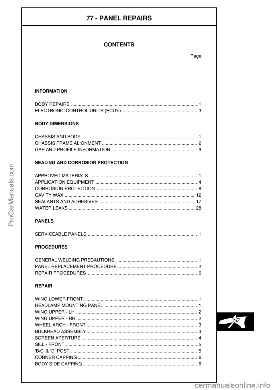
CONTENTS
Page
INFORMATION
BODY REPAIRS 1..................................................................................................
ELECTRONIC CONTROL UNITS (ECU’s) 3..........................................................
BODY DIMENSIONS
CHASSIS AND BODY 1..........................................................................................
CHASSIS FRAME ALIGNMENT 2..........................................................................
GAP AND PROFILE INFORMATION 9...................................................................
SEALING AND CORROSION PROTECTION
APPROVED MATERIALS 1....................................................................................
APPLICATION EQUIPMENT 4...............................................................................
CORROSION PROTECTION 8...............................................................................
CAVITY WAX 12.....................................................................................................
SEALANTS AND ADHESIVES 17..........................................................................
WATER LEAKS 28..................................................................................................
PANELS
SERVICEABLE PANELS 1.....................................................................................
PROCEDURES
GENERAL WELDING PRECAUTIONS 1...............................................................
PANEL REPLACEMENT PROCEDURE 2..............................................................
REPAIR PROCEDURES 6......................................................................................
REPAIR
WING LOWER FRONT 1........................................................................................
HEADLAMP MOUNTING PANEL 1........................................................................
WING UPPER - LH 2..............................................................................................
WING UPPER - RH 2..............................................................................................
WHEEL ARCH - FRONT 3......................................................................................
BULKHEAD ASSEMBLY 3......................................................................................
SCREEN APERTURE 4..........................................................................................
SILL - FRONT 5......................................................................................................
’B/C’&’D’POST 5..................................................................................................
CORNER CAPPING 6.............................................................................................
BODY SIDE CAPPING 6.........................................................................................
ProCarManuals.com
Page 510 of 667
PANEL REPAIRS
1
INFORMATION BODY REPAIRS
Body shells are of riveted, bolted and welded
construction and are bolted to the chassis frame.
It is essential that design dimensions and strength are
restored in accident rectification. It is important that
neither structural weakness nor excessive local
stiffness are introduced into the vehicle during body or
chassis repair.
Repairs usually involve a combination of operations
ranging from straightening procedures to renewal of
either individual panels or panel assemblies. The
repairer will determine the repair method and this
decision will take into account a balance of economics
between labour and material costs and the availability
of repair facilities in both equipment and skills. It may
also involve considerations of vehicles down-time,
replacement vehicle availability and repair turn-around
time.
It is expected that a repairer will select the best and
most economic repair method possible, making use of
the facilities available. The instructions given are
intended to assist a skilled body repairer by expanding
approved procedures for panel replacement with the
objective of restoring the vehicle to a safe running
condition and effecting a repair which is visually
acceptable and which, even to the experienced eye,
does not advertise the fact that it has been damaged.
This does not necessarily mean that the repaired
vehicle will be identical in all respects with original
factory build. Repair facilities cannot always duplicate
methods of construction used during production.
The panel repairs shown in this section are all based
on a 110 Station Wagon. Therefore all illustrations
and text relate only to this model. Although certain
areas of the vehicle, such as the front end, are
relevant to all models.
Operations covered in this Manual do not include
reference to testing the vehicle after repair. It is
essential that work is inspected and suspension
geometry checked after completion and if necessary a
road test of the vehicle is carried out, particularly
where safety related items are concerned.Where major units have been disconnected or
removed, it is necessary to ensure that fluid levels are
checked and topped up when necessary. It is also
necessary to ensure that the repaired vehicle is in a
roadworthy condition in respect of tyre pressures,
lights, washer fluid etc.
Body repairs often involve the removal of mechanical
and electrical units as well as associated wiring.
Where this is necessary use the relevant section in
this manual.
Taking into consideration the differences in body
styles, steering and suspension systems as well as
engine and suspension layouts, the location of the
following components as applicable to a particular
vehicle is critical:
Front suspension upper damper
mountings.
Front suspension or sub frame mountings.
Engine mountings on RH and LH chassis
longitudinals.
Rear suspension upper damper mountings.
Rear suspension mountings or lower
pivots.
Steering rack mountings.
Additional points which can be used to check
alignment and assembly are:
Inner holes in crossmember - side - main
floor.
Holes in valance front assembly.
Body to chassis mounting holes.
Holes in rear floor.
Holes in rear lower panels or extension
rear floor.
Fuel tank mountings.
Apertures for windscreen, backlight, bonnet and doors
can be checked by offering up an undamaged
component as a gauge and also by measuring known
dimensions.See BODY DIMENSIONS section.
ProCarManuals.com
Page 511 of 667
77PANEL REPAIRS
2
INFORMATION Straightening
Whenever possible, chassis structural members
should be cold straightened under tension. Do not
attempt to straighten with a single pull, but rework the
damaged area using a series of pulls, releasing
tension between each stage and using the opportunity
to check alignment.
Body jig
Unless damage is limited to cosmetic panels, all repair
work to body members must be carried out on a body
jig, to ensure that impact damage has not spread into
more remote parts of the body structure. Mounting on
a jig will also ensure that the straightening and panel
replacement procedures do not cause further
distortion. If original dimensions cannot be
satisfactorily restored by these methods, damaged
structural members should be replaced. Damaged
areas should be cut away using a high speed saw,
NOT an oxy-acetylene torch.
As a rule, body dimensions are symmetrical about the
centre line. A good initial check for distortion is
therefore to measure diagonally and to investigate
apparent differences in dimensions.Inspection
Every accident produces individual differences in
damage. Each repair is influenced by the extent of the
damage and by the facilities and equipment available
for its rectification.
Most accident damage can be visually inspected and
the approximate extent of the damage assessed.
Sometimes deformation will extend beyond the area
of direct damage, and the severity of this must be
accurately established so that steps may be taken to
restore critical body components to their original
dimensions.
An initial check of critical dimensions can be carried
out by means of drop checks or (preferably) trammels.
Gauges are available which will check accurately for
body twist. Where repairs necessitate renewal of a
critical body component it is recommended that a
body jig is used.
ProCarManuals.com
Page 514 of 667
PANEL REPAIRS
1
BODY DIMENSIONS CHASSIS AND BODY
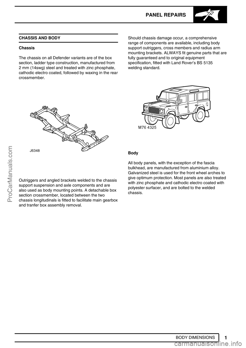
Chassis
The chassis on all Defender variants are of the box
section, ladder type construction, manufactured from
2 mm (14swg) steel and treated with zinc phosphate,
cathodic electro coated, followed by waxing in the rear
crossmember.
Outriggers and angled brackets welded to the chassis
support suspension and axle components and are
also used as body mounting points. A detachable box
section crossmember, located between the two
chassis longitudinals is fitted to facilitate main gearbox
and tranfer box assembly removal.Should chassis damage occur, a comprehensive
range of components are available, including body
support outriggers, cross members and radius arm
mounting brackets. ALWAYS fit genuine parts that are
fully guaranteed and to original equipment
specification, fitted with Land Rover’s BS 5135
welding standard.
Body
All body panels, with the exception of the fascia
bulkhead, are manufactured from aluminium alloy.
Galvanized steel is used for the front wheel arches to
give optimum protection. Most panels are also treated
with zinc phosphate and cathodic electro coated with
polyester surfacer, and are bolted to the welded
chassis.
ProCarManuals.com