LAND ROVER DISCOVERY 1995 Service Repair Manual
Manufacturer: LAND ROVER, Model Year: 1995, Model line: DISCOVERY, Model: LAND ROVER DISCOVERY 1995Pages: 976, PDF Size: 14.57 MB
Page 691 of 976
76CHASSIS AND BODY
24
REPAIR SEAT BASE TORSION BARS
Service repair no - 76.71.34
Remove
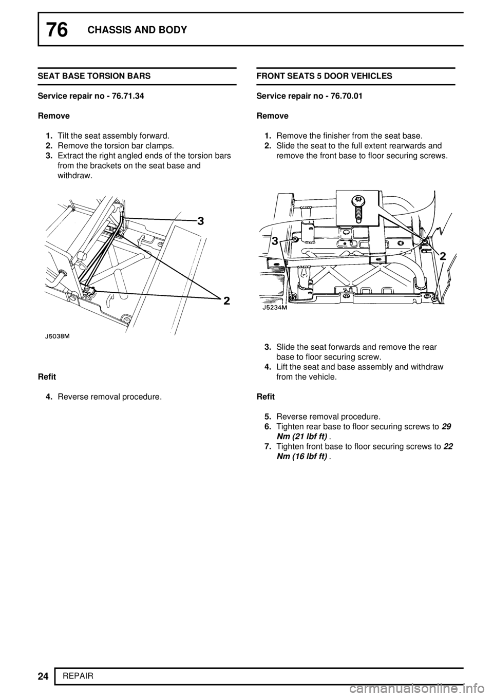
1.Tilt the seat assembly forward.
2.Remove the torsion bar clamps.
3.Extract the right angled ends of the torsion bars
from the brackets on the seat base and
withdraw.
Refit
4.Reverse removal procedure.FRONT SEATS 5 DOOR VEHICLES
Service repair no - 76.70.01
Remove
1.Remove the finisher from the seat base.
2.Slide the seat to the full extent rearwards and
remove the front base to floor securing screws.
3.Slide the seat forwards and remove the rear
base to floor securing screw.
4.Lift the seat and base assembly and withdraw
from the vehicle.
Refit
5.Reverse removal procedure.
6.Tighten rear base to floor securing screws to
29
Nm (21 lbf ft)
.
7.Tighten front base to floor securing screws to
22
Nm (16 lbf ft)
.
Page 692 of 976
CHASSIS AND BODY
25
REPAIR FRONT SEAT COVERS
Service repair no - 76.70.14
Cushion
Remove
1.Remove the seat from the base.
2.Invert the seat on a suitable clean bench.
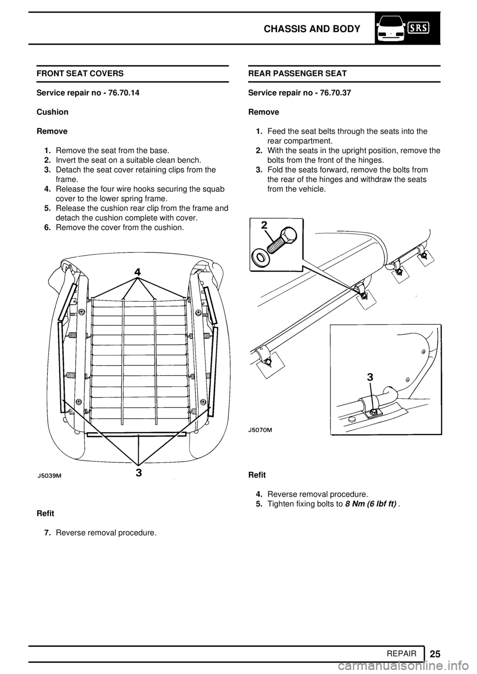
3.Detach the seat cover retaining clips from the
frame.
4.Release the four wire hooks securing the squab
cover to the lower spring frame.
5.Release the cushion rear clip from the frame and
detach the cushion complete with cover.
6.Remove the cover from the cushion.
Refit
7.Reverse removal procedure.REAR PASSENGER SEAT
Service repair no - 76.70.37
Remove
1.Feed the seat belts through the seats into the
rear compartment.
2.With the seats in the upright position, remove the
bolts from the front of the hinges.
3.Fold the seats forward, remove the bolts from
the rear of the hinges and withdraw the seats
from the vehicle.
Refit
4.Reverse removal procedure.
5.Tighten fixing bolts to
8 Nm (6 lbf ft).
Page 693 of 976
76CHASSIS AND BODY
26
REPAIR REAR SEAT SQUAB
Service repair no - 76.70.38
Remove
1.Fold the rear seat down.
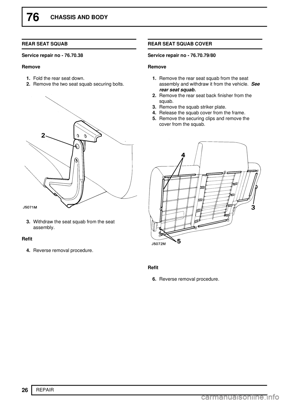
2.Remove the two seat squab securing bolts.
3.Withdraw the seat squab from the seat
assembly.
Refit
4.Reverse removal procedure.REAR SEAT SQUAB COVER
Service repair no - 76.70.79/80
Remove
1.Remove the rear seat squab from the seat
assembly and withdraw it from the vehicle.
See
rear seat squab.
2.Remove the rear seat back finisher from the
squab.
3.Remove the squab striker plate.
4.Release the squab cover from the frame.
5.Remove the securing clips and remove the
cover from the squab.
Refit
6.Reverse removal procedure.
Page 694 of 976
CHASSIS AND BODY
27
REPAIR REAR SEAT CUSHION COVER
Service repair no - 76.70.88/89
Remove
NOTE: The procedure for removing both
left and right hand seat cushions is the
same.
1.Remove the rear seat assembly from the
vehicle.
See rear passenger seat.
2.Remove the seat squab.
3.Remove the seat cushion.
4.Remove the cushion base cover retaining
screws and withdraw the cover.
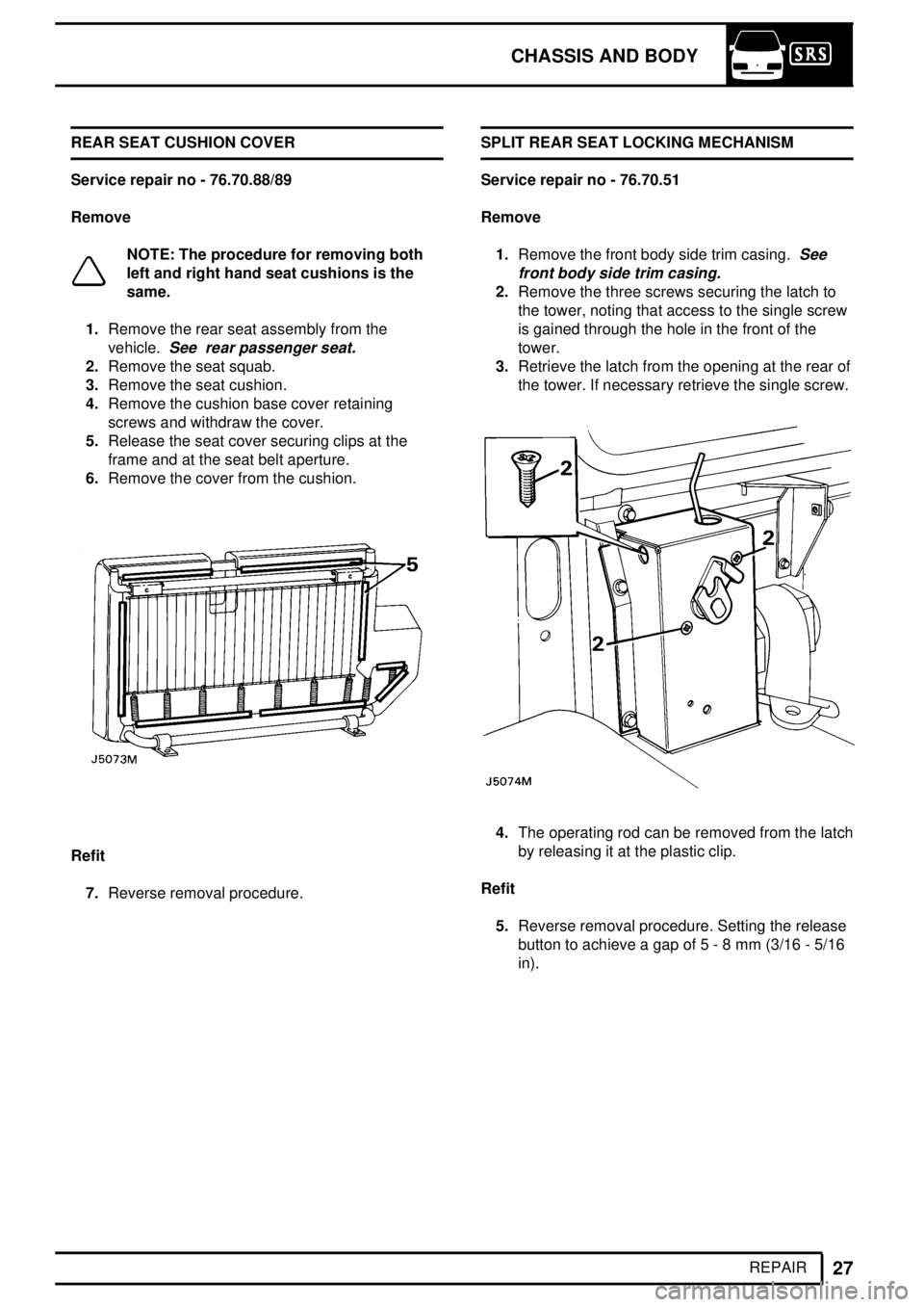
5.Release the seat cover securing clips at the
frame and at the seat belt aperture.
6.Remove the cover from the cushion.
Refit
7.Reverse removal procedure.SPLIT REAR SEAT LOCKING MECHANISM
Service repair no - 76.70.51
Remove
1.Remove the front body side trim casing.
See
front body side trim casing.
2.Remove the three screws securing the latch to
the tower, noting that access to the single screw
is gained through the hole in the front of the
tower.
3.Retrieve the latch from the opening at the rear of
the tower. If necessary retrieve the single screw.
4.The operating rod can be removed from the latch
by releasing it at the plastic clip.
Refit
5.Reverse removal procedure. Setting the release
button to achieve a gap of 5 - 8 mm (3/16 - 5/16
in).
Page 695 of 976
76CHASSIS AND BODY
28
REPAIR REAR FOLD DOWN SEATS
Service repair no - 76.71.23
Seat and squab
Remove
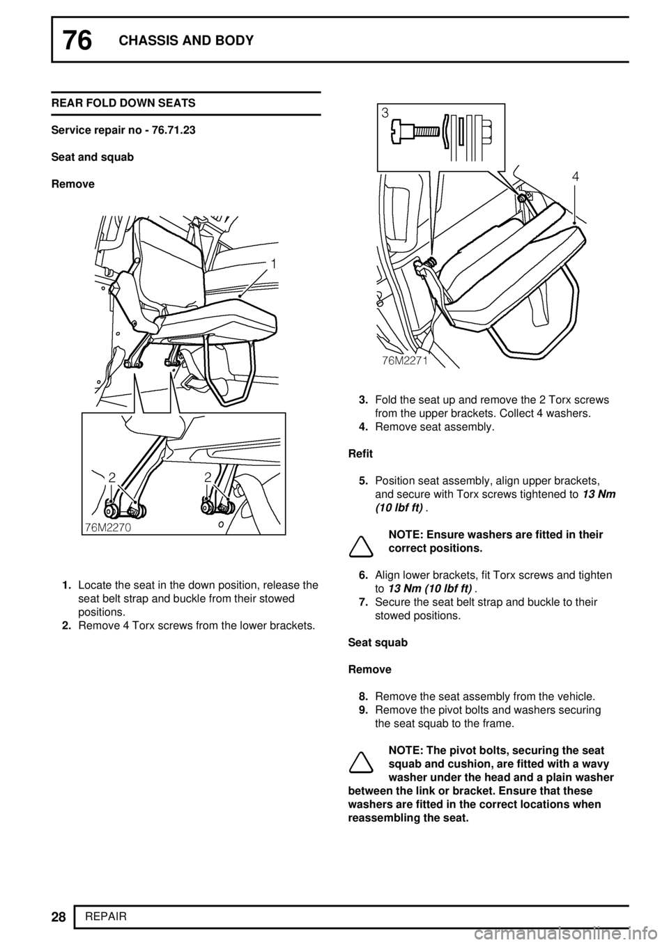
1.Locate the seat in the down position, release the
seat belt strap and buckle from their stowed
positions.
2.Remove 4 Torx screws from the lower brackets.
3.Fold the seat up and remove the 2 Torx screws
from the upper brackets. Collect 4 washers.
4.Remove seat assembly.
Refit
5.Position seat assembly, align upper brackets,
and secure with Torx screws tightened to
13 Nm
(10 lbf ft)
.
NOTE: Ensure washers are fitted in their
correct positions.
6.Align lower brackets, fit Torx screws and tighten
to
13 Nm (10 lbf ft).
7.Secure the seat belt strap and buckle to their
stowed positions.
Seat squab
Remove
8.Remove the seat assembly from the vehicle.
9.Remove the pivot bolts and washers securing
the seat squab to the frame.
NOTE: The pivot bolts, securing the seat
squab and cushion, are fitted with a wavy
washer under the head and a plain washer
between the link or bracket. Ensure that these
washers are fitted in the correct locations when
reassembling the seat.
Page 696 of 976
CHASSIS AND BODY
29
REPAIR 10.Remove the pivot bolts and washers securing
the hinge links to the seat squab.
11.If necessary remove the clips securing the cover
and detach the cover.
Refit
12.Reverse removal procedure.
Seat cushion
Remove
13.Remove the seat from the vehicle.
14.Remove the seat squab.
15.Remove the pivot bolts and washers securing
the hinge bracket and detach the bracket.
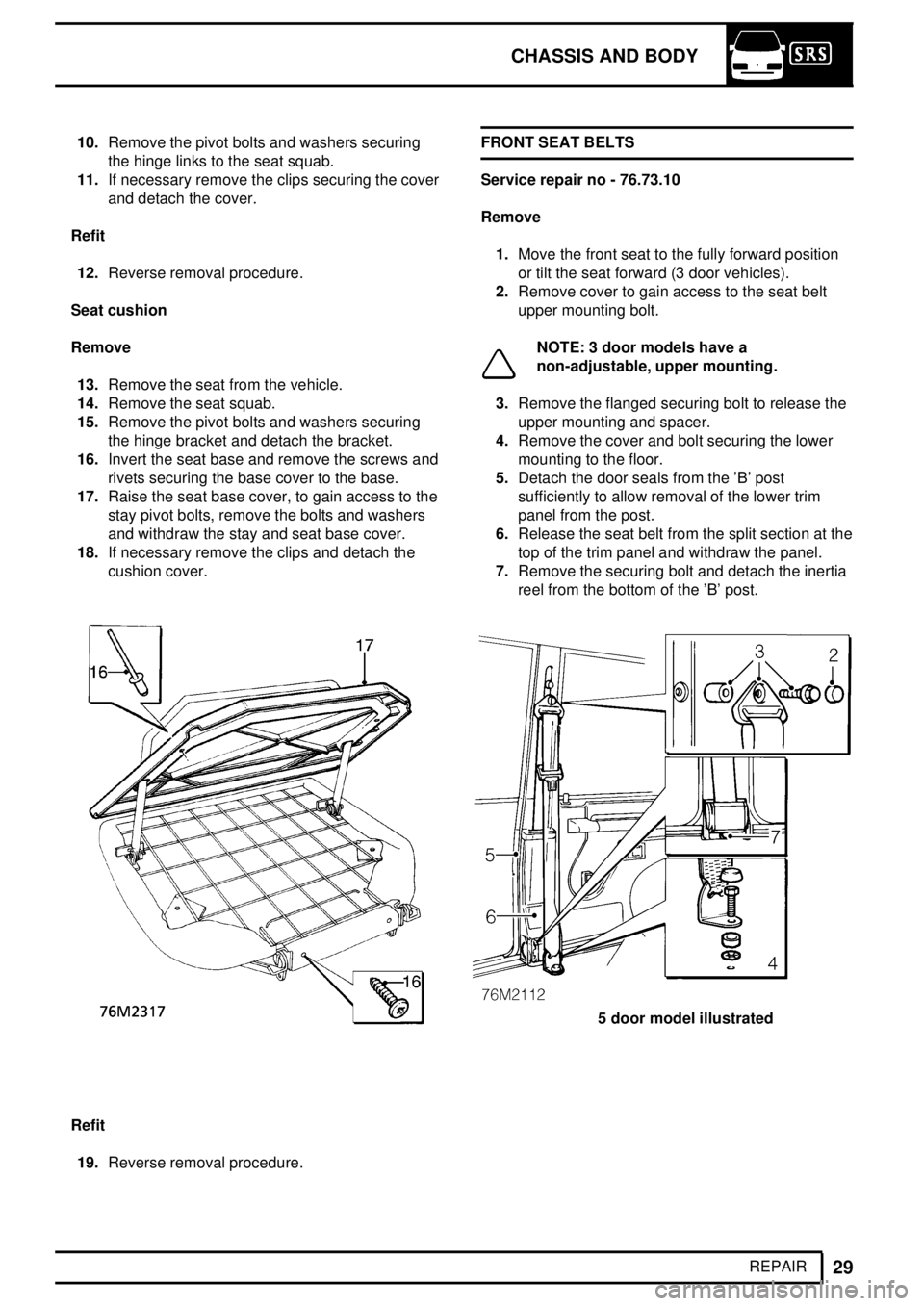
16.Invert the seat base and remove the screws and
rivets securing the base cover to the base.
17.Raise the seat base cover, to gain access to the
stay pivot bolts, remove the bolts and washers
and withdraw the stay and seat base cover.
18.If necessary remove the clips and detach the
cushion cover.
Refit
19.Reverse removal procedure.FRONT SEAT BELTS
Service repair no - 76.73.10
Remove
1.Move the front seat to the fully forward position
or tilt the seat forward (3 door vehicles).
2.Remove cover to gain access to the seat belt
upper mounting bolt.
NOTE: 3 door models have a
non-adjustable, upper mounting.
3.Remove the flanged securing bolt to release the
upper mounting and spacer.
4.Remove the cover and bolt securing the lower
mounting to the floor.
5.Detach the door seals from the 'B' post
sufficiently to allow removal of the lower trim
panel from the post.
6.Release the seat belt from the split section at the
top of the trim panel and withdraw the panel.
7.Remove the securing bolt and detach the inertia
reel from the bottom of the 'B' post.
5 door model illustrated
Page 697 of 976
76CHASSIS AND BODY
30
REPAIR
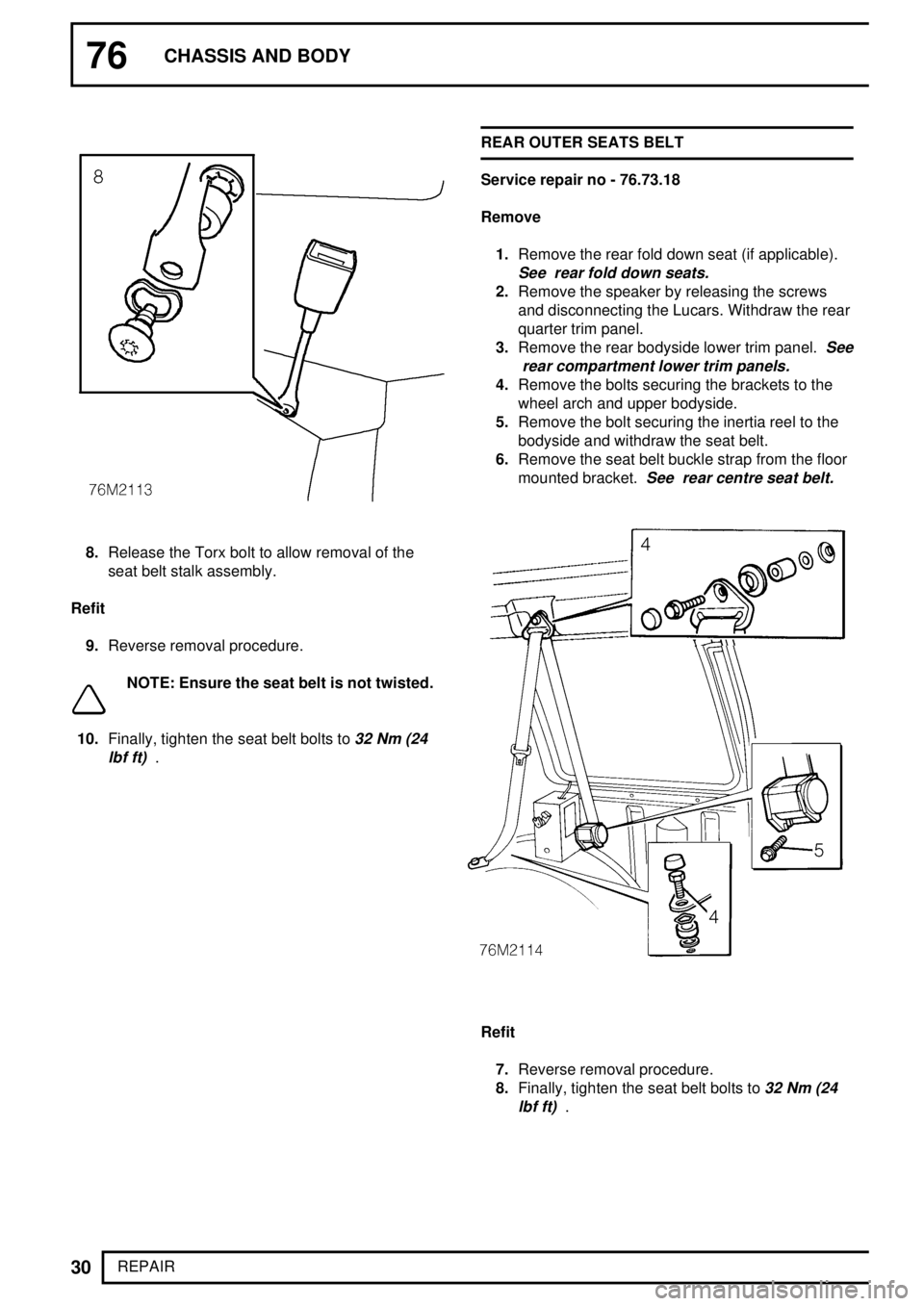
8.Release the Torx bolt to allow removal of the
seat belt stalk assembly.
Refit
9.Reverse removal procedure.
NOTE: Ensure the seat belt is not twisted.
10.Finally, tighten the seat belt bolts to
32 Nm (24
lbf ft)
.REAR OUTER SEATS BELT
Service repair no - 76.73.18
Remove
1.Remove the rear fold down seat (if applicable).
See rear fold down seats.
2.Remove the speaker by releasing the screws
and disconnecting the Lucars. Withdraw the rear
quarter trim panel.
3.Remove the rear bodyside lower trim panel.
See
rear compartment lower trim panels.
4.Remove the bolts securing the brackets to the
wheel arch and upper bodyside.
5.Remove the bolt securing the inertia reel to the
bodyside and withdraw the seat belt.
6.Remove the seat belt buckle strap from the floor
mounted bracket.
See rear centre seat belt.
Refit
7.Reverse removal procedure.
8.Finally, tighten the seat belt bolts to
32 Nm (24
lbf ft)
.
Page 698 of 976
CHASSIS AND BODY
31
REPAIR REAR CENTRE SEAT BELT
Service repair no - 76.73.20
Remove
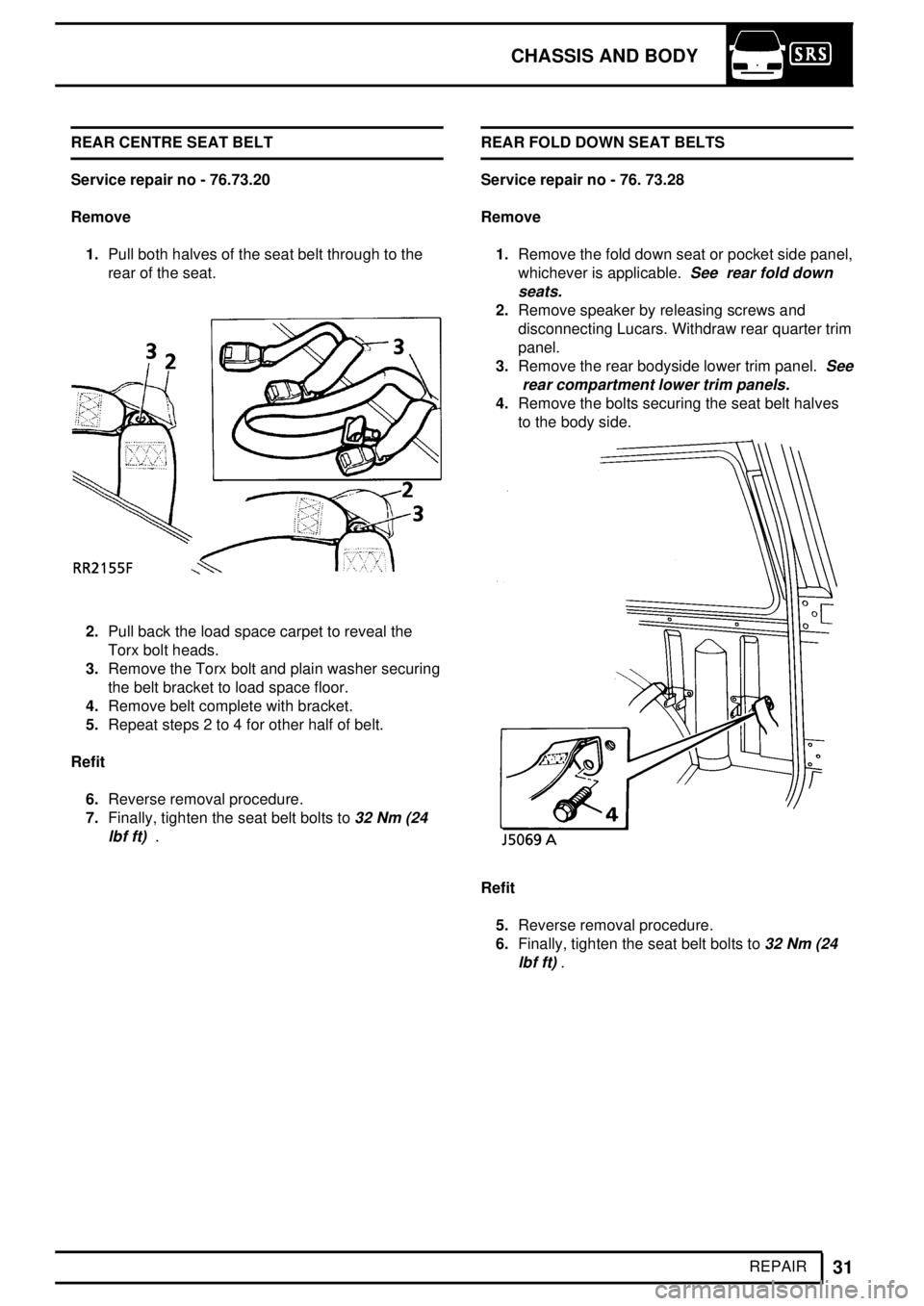
1.Pull both halves of the seat belt through to the
rear of the seat.
2.Pull back the load space carpet to reveal the
Torx bolt heads.
3.Remove the Torx bolt and plain washer securing
the belt bracket to load space floor.
4.Remove belt complete with bracket.
5.Repeat steps 2 to 4 for other half of belt.
Refit
6.Reverse removal procedure.
7.Finally, tighten the seat belt bolts to
32 Nm (24
lbf ft)
.REAR FOLD DOWN SEAT BELTS
Service repair no - 76. 73.28
Remove
1.Remove the fold down seat or pocket side panel,
whichever is applicable.
See rear fold down
seats.
2.Remove speaker by releasing screws and
disconnecting Lucars. Withdraw rear quarter trim
panel.
3.Remove the rear bodyside lower trim panel.
See
rear compartment lower trim panels.
4.Remove the bolts securing the seat belt halves
to the body side.
Refit
5.Reverse removal procedure.
6.Finally, tighten the seat belt bolts to
32 Nm (24
lbf ft)
.
Page 699 of 976
76CHASSIS AND BODY
32
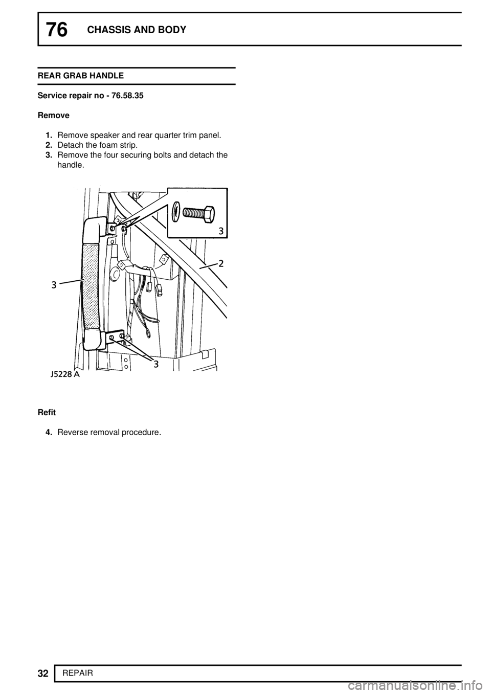
REPAIR REAR GRAB HANDLE
Service repair no - 76.58.35
Remove
1.Remove speaker and rear quarter trim panel.
2.Detach the foam strip.
3.Remove the four securing bolts and detach the
handle.
Refit
4.Reverse removal procedure.
Page 700 of 976
![LAND ROVER DISCOVERY 1995 Service Repair Manual CHASSIS AND BODY
33
REPAIR WINGS [FENDERS]
Service repair no - 76.10.24
Remove
1.Disconnect battery negative lead.
2.Remove the headlamp surround.
3.Remove the front bumper assembly.
4.Remove the indi LAND ROVER DISCOVERY 1995 Service Repair Manual CHASSIS AND BODY
33
REPAIR WINGS [FENDERS]
Service repair no - 76.10.24
Remove
1.Disconnect battery negative lead.
2.Remove the headlamp surround.
3.Remove the front bumper assembly.
4.Remove the indi](/img/64/57245/w960_57245-699.png)
CHASSIS AND BODY
33
REPAIR WINGS [FENDERS]
Service repair no - 76.10.24
Remove
1.Disconnect battery negative lead.
2.Remove the headlamp surround.
3.Remove the front bumper assembly.
4.Remove the indicator repeater light.
5.Remove the four screws securing the wing
[fender] at the 'A' post.
6.Remove the bolts securing the bottom of the
wing [fender] at the bumper retaining bracket
and at the sill finisher.
7.If removing the RH wing [fender] loosen the
radio aerial securing nut.
8.Remove the seven bolts from the drain channel
in the top of the wing [fender].
9.Break the sealed joints at the valance and 'A'
post; then complete the removal of the wing
[fender]. If removing a RH wing withdraw the
wing [fender] sufficiently to allow removal of the
aerial before completing the removal.Cleaning/painting
10.Thoroughly clean all traces of existing sealant
from the sealing faces of the valance and 'A'
post.
11.Paint the cleaned surfaces with etch primer.
12.If the existing wing [fender] is to be refitted
repeat the cleaning and painting procedure on
the wing [fender] sealing surfaces.
Refit
13.Apply 3M 8572 Bolted Panel Sealer to the joint
faces on the valance and 'A' post and to the
bracket face.
14.Refit the wing [fender], on RH wings [fenders] fit
the radio aerial, and secure with the bolts and
screws ensuring that the wing [fender] correctly
aligns with the bonnet [hood].