petrol LAND ROVER DISCOVERY 1995 Owner's Manual
[x] Cancel search | Manufacturer: LAND ROVER, Model Year: 1995, Model line: DISCOVERY, Model: LAND ROVER DISCOVERY 1995Pages: 873, PDF Size: 12.89 MB
Page 566 of 873
STEERING
5
OVERHAUL Rack thrust pad and adjuster
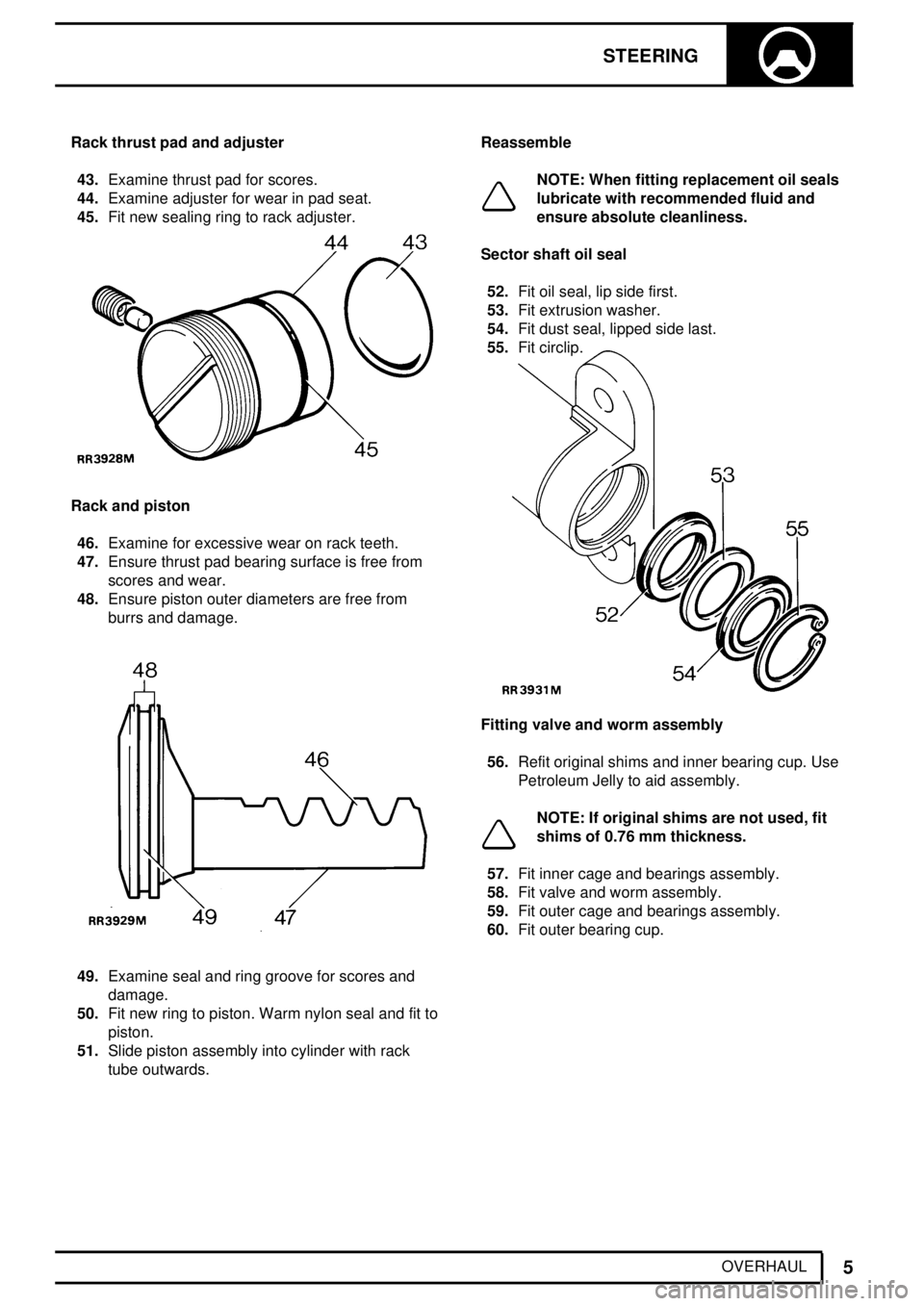
43.Examine thrust pad for scores.
44.Examine adjuster for wear in pad seat.
45.Fit new sealing ring to rack adjuster.
Rack and piston
46.Examine for excessive wear on rack teeth.
47.Ensure thrust pad bearing surface is free from
scores and wear.
48.Ensure piston outer diameters are free from
burrs and damage.
49.Examine seal and ring groove for scores and
damage.
50.Fit new ring to piston. Warm nylon seal and fit to
piston.
51.Slide piston assembly into cylinder with rack
tube outwards.Reassemble
NOTE: When fitting replacement oil seals
lubricate with recommended fluid and
ensure absolute cleanliness.
Sector shaft oil seal
52.Fit oil seal, lip side first.
53.Fit extrusion washer.
54.Fit dust seal, lipped side last.
55.Fit circlip.
Fitting valve and worm assembly
56.Refit original shims and inner bearing cup. Use
Petroleum Jelly to aid assembly.
NOTE: If original shims are not used, fit
shims of 0.76 mm thickness.
57.Fit inner cage and bearings assembly.
58.Fit valve and worm assembly.
59.Fit outer cage and bearings assembly.
60.Fit outer bearing cup.
Page 600 of 873

BRAKES
9
DESCRIPTION AND OPERATION Petrol engine vacuum system
The vacuum necessary to operate the brake servo on
petrol engine vehicles is provided by the engine inlet
manifold. During normal operation of the brakes only a
small volume of air is drawn from the servo and into
the inlet manifold or plenum chamber. However any
excessive air leaks due to damage in the brake servo
system or manifold hose connection, will effect the
mixture strength and ECM fuelling calculations on
engines equipped with an MFI system.
Diesel engine vacuum system
As the diesel engine inlet system does not produce
depression sufficient to operate the brake servo, it is
necessary to install an engine driven vacuum pump.
During normal operation of the brakes only a small
volume of air is drawn from the servo by the vacuum
pump. However as the pump exhausts air into the
engine crankcase atmosphere, an air leak due to
damage in the brake servo system or pump hose
connection, may cause excessive crankcase
pressure.
Page 603 of 873

BRAKES
1
REPAIR GENERAL BRAKE SERVICE PRACTICE
Brake fluid precautions
WARNING: Do not allow brake fluid to
come into contact with eyes or skin.
CAUTION: Brake fluid can damage
paintwork, if spilled wash off immediately
with plenty of clean water.
CAUTION: Use only correct grade of brake
fluid. If an assembly fluid is required use
ONLY brake fluid. Do NOT use mineral oil,
i.e. engine oil etc.
CAUTION: Thoroughly clean all brake
calipers, pipes and fittings before
commencing work on any part of the brake
system. Failure to do so could cause foreign
matter to enter the system and cause damage to
seals and pistons which will seriously impair the
efficiency of the brake system.
·To ensure the brake system efficiency is not
impaired the following warnings must be
adhered to :-
·DO NOT use any petroleum based cleaning
fluids or any proprietary fluids containing
petrol.
·DO NOT use brake fluid previously bled from
the system.
·DO NOT flush the brake system with any fluid
other than the recommended brake fluid.
The brake system should be drained and flushed
at the recommended service intervals.
Cover all electrical terminals carefully to make
absolutely certain that no fluid enters the
terminals and plugs.FLUID LEVEL CHECK / TOP UP
WARNING: Clean reservoir body and filler
cap before removing cap. Use only fluid
from a sealed container.
1.Park vehicle on level ground.
2.Check level is between 'MIN' and 'MAX' marks.
3.If level is below 'MIN' mark top up fluid level to
'MAX' mark on reservoir, using correct fluid.
See
LUBRICANTS, FLUIDS AND CAPACITIES,
Information, Recommended Lubricants and
Fluids
Do not fill reservoir above maximum line
Page 746 of 873

80HEATING AND VENTILATION
4
REPAIR WATER VALVE
Service repair no - 80.10.16
Remove
1.Disconnect vacuum pipe from water valve.
2.Slacken 4 clips securing hoses to water valve.
3.Use a thin blade to break seal between hoses
and nozzles
4.Disconnect heater inlet hose from valve.
NOTE: A quantity of coolant will be
released.
5.Disconnect heater outlet hose from valve.
6.Lever valve from coolant pipe hoses.
Refit
7.Reverse removal procedure. Lightly lubricate
water valve nozzles with petroleum jelly.
8.Reverse removal procedure. Top-up engine
coolantVACUUM SWITCH - WATER VALVE
Service repair no - 80.10.36
Remove
1.Release emission pipe from retaining clip.
2.Remove bolt securing switch to bulkhead.
3.Disconnect multiplug from switch.
4.Disconnect 2 vacuum pipes and remove vacuum
switch.
Refit
5.Reverse removal procedure.
Page 823 of 873
ELECTRICAL
3
REPAIR BATTERY
Service repair no - 86.15.01
NOTE: Some vehicles are fitted with a
battery backed-up sounder. Disconnecting
the vehicle battery will cause the alarm to
sound unless the following procedure is followed:
1.Turn starter switch 'ON' then 'OFF'.
2.Disconnect battery WITHIN 15 SECONDS (see
WARNING).
If alarm is accidentally activated, ensure sounder is
connected and silence by turning the starter switch to
position II.
Remove
WARNING: During battery removal or
before carrying out any repairs or
maintenance to electrical components
always disconnect battery negative lead first. If
positive lead is disconnected with negative lead in
place, accidental contact of wrench to any
grounded metal part could cause a severe spark,
possibly resulting in personal injury. Upon
installation of battery connect positive lead first.
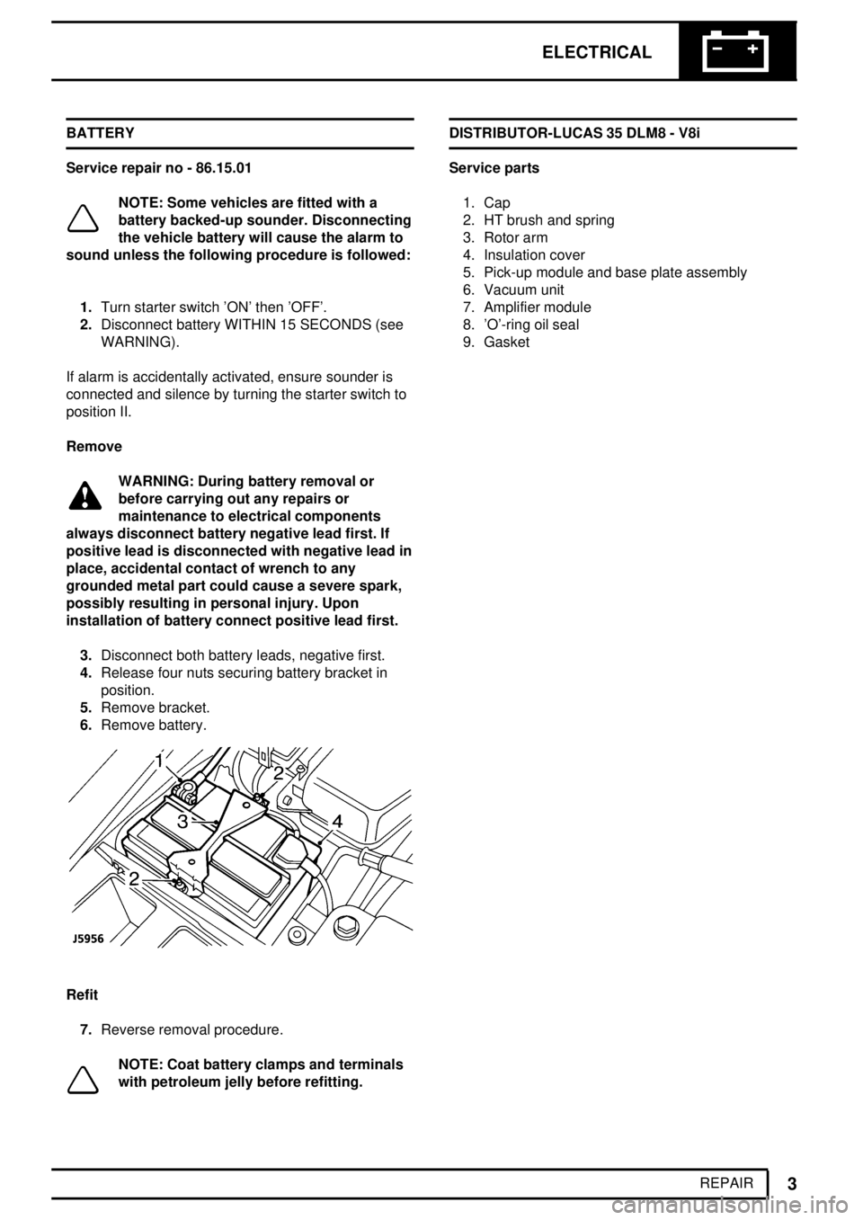
3.Disconnect both battery leads, negative first.
4.Release four nuts securing battery bracket in
position.
5.Remove bracket.
6.Remove battery.
Refit
7.Reverse removal procedure.
NOTE: Coat battery clamps and terminals
with petroleum jelly before refitting.DISTRIBUTOR-LUCAS 35 DLM8 - V8i
Service parts
1. Cap
2. HT brush and spring
3. Rotor arm
4. Insulation cover
5. Pick-up module and base plate assembly
6. Vacuum unit
7. Amplifier module
8. 'O'-ring oil seal
9. Gasket