warning light LAND ROVER DISCOVERY 1999 Workshop Manual
[x] Cancel search | Manufacturer: LAND ROVER, Model Year: 1999, Model line: DISCOVERY, Model: LAND ROVER DISCOVERY 1999Pages: 1529, PDF Size: 34.8 MB
Page 29 of 1529

CONTENTS
26 CONTENTS
LIGHTING.................................................................................................. 86-2-1
ADJUSTMENTS
Headlamps beam alignment - up to 03MY ..................................................................................... 86-2-1
Headlamps beam alignment - from 03MY ...................................................................................... 86-2-2
REPAIRS
Lamp - front repeater - up to 03MY ................................................................................................ 86-2-3
Headlamp - up to 03MY .................................................................................................................. 86-2-4
Headlamp - from 03MY .................................................................................................................. 86-2-5
Lamp - tail ..................................................................................................................................... 86-2-6
Lamp - front fog up to 03MY ........................................................................................................... 86-2-6
Lamp - front fog from 03MY ............................................................................................................ 86-2-7
Housing - number plate lamp ......................................................................................................... 86-2-8
Motor - headlamp levelling ............................................................................................................ 86-2-9
Lamp - stop - centre high mounted (CHMSL) .............................................................................. 86-2-10
Lamp - tail/flasher - bumper ............................................................................................................ 86-2-10
Lamp - interior - front .................................................................................................................... 86-2-11
Lamp - interior - rear ..................................................................................................................... 86-2-11
Rheostat - panel lights dimmer ...................................................................................................... 86-2-12
Switch - hazard warning ................................................................................................................ 86-2-13
Switch - indicator and exterior lighting - combined ......................................................................... 86-2-13
Socket - accessory ........................................................................................................................ 86-2-14
Switch - front/rear fog lamps ......................................................................................................... 86-2-14
BODY CONTROL UNIT ............................................................................ 86-3-1
DESCRIPTION AND OPERATION
Description ...................................................................................................................................... 86-3-1
Operation ........................................................................................................................................ 86-3-19
REPAIRS
Body control unit (BCU) .................................................................................................................. 86-3-35
ALARM SYSTEM AND HORN.................................................................. 86-4-1
DESCRIPTION AND OPERATION
Alarm system component layout..................................................................................................... 86-4-2
Alarm system block diagram........................................................................................................... 86-4-4
Description ...................................................................................................................................... 86-4-5
Operation ........................................................................................................................................ 86-4-17
REPAIR
Switch - central door locking ......................................................................................................... 86-4-25
Switches - horn ............................................................................................................................. 86-4-25
Vehicle horn .................................................................................................................................. 86-4-26
Sounder - alarm ............................................................................................................................ 86-4-26
Sounder - battery backed-up (BBUS) ............................................................................................. 86-4-27
Switch - bonnet ............................................................................................................................. 86-4-27
Receiver - alarm system - models with sunroof ............................................................................. 86-4-28
Receiver - alarm system - models without sunroof ......................................................................... 86-4-28
Coil - passive immobilisation ........................................................................................................ 86-4-29
Page 50 of 1529

GENERAL INFORMATION
03-15
Hose clips
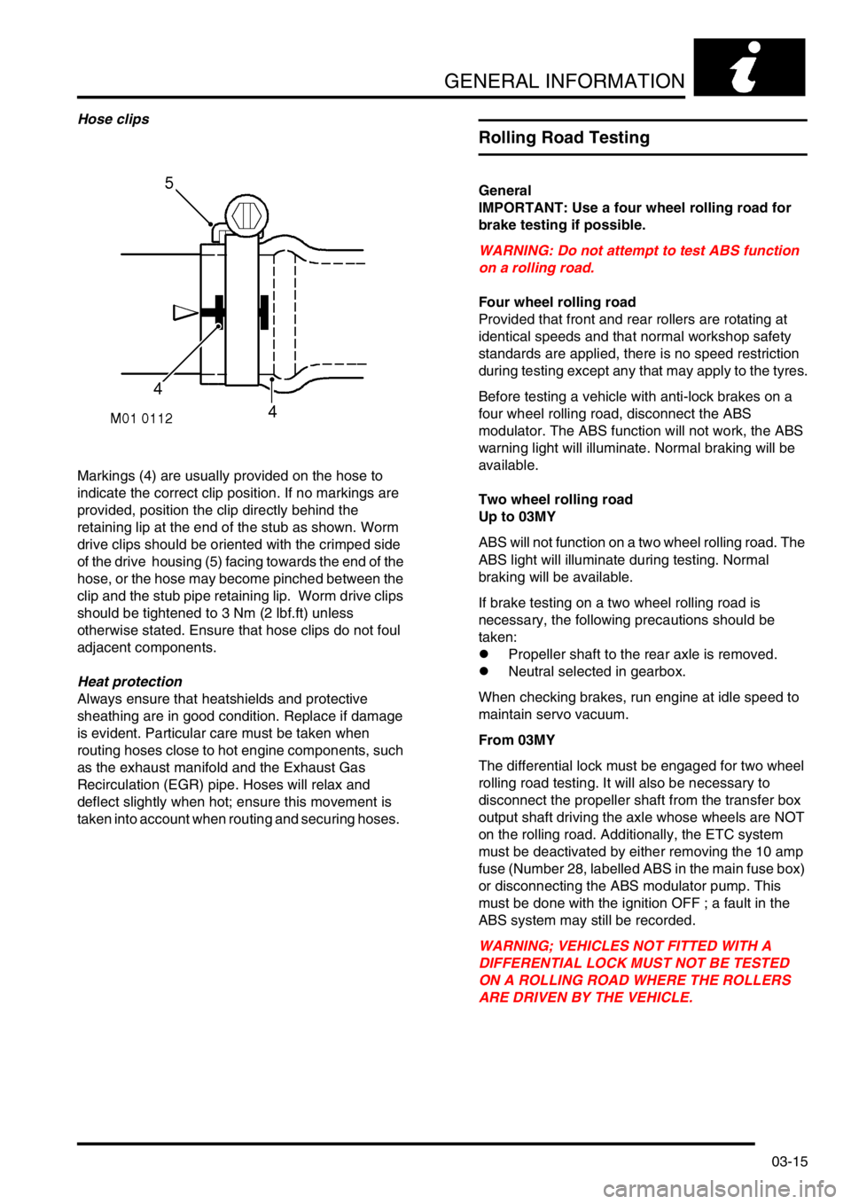
Markings (4) are usually provided on the hose to
indicate the correct clip position. If no markings are
provided, position the clip directly behind the
retaining lip at the end of the stub as shown. Worm
drive clips should be oriented with the crimped side
of the drive housing (5) facing towards the end of the
hose, or the hose may become pinched between the
clip and the stub pipe retaining lip. Worm drive clips
should be tightened to 3 Nm (2 lbf.ft) unless
otherwise stated. Ensure that hose clips do not foul
adjacent components.
Heat protection
Always ensure that heatshields and protective
sheathing are in good condition. Replace if damage
is evident. Particular care must be taken when
routing hoses close to hot engine components, such
as the exhaust manifold and the Exhaust Gas
Recirculation (EGR) pipe. Hoses will relax and
deflect slightly when hot; ensure this movement is
taken into account when routing and securing hoses.
Rolling Road Testing
General
IMPORTANT: Use a four wheel rolling road for
brake testing if possible.
WARNING: Do not attempt to test ABS function
on a rolling road.
Four wheel rolling road
Provided that front and rear rollers are rotating at
identical speeds and that normal workshop safety
standards are applied, there is no speed restriction
during testing except any that may apply to the tyres.
Before testing a vehicle with anti-lock brakes on a
four wheel rolling road, disconnect the ABS
modulator. The ABS function will not work, the ABS
warning light will illuminate. Normal braking will be
available.
Two wheel rolling road
Up to 03MY
ABS will not function on a two wheel rolling road. The
ABS light will illuminate during testing. Normal
braking will be available.
If brake testing on a two wheel rolling road is
necessary, the following precautions should be
taken:
lPropeller shaft to the rear axle is removed.
lNeutral selected in gearbox.
When checking brakes, run engine at idle speed to
maintain servo vacuum.
From 03MY
The differential lock must be engaged for two wheel
rolling road testing. It will also be necessary to
disconnect the propeller shaft from the transfer box
output shaft driving the axle whose wheels are NOT
on the rolling road. Additionally, the ETC system
must be deactivated by either removing the 10 amp
fuse (Number 28, labelled ABS in the main fuse box)
or disconnecting the ABS modulator pump. This
must be done with the ignition OFF ; a fault in the
ABS system may still be recorded.
WARNING; VEHICLES NOT FITTED WITH A
DIFFERENTIAL LOCK MUST NOT BE TESTED
ON A ROLLING ROAD WHERE THE ROLLERS
ARE DRIVEN BY THE VEHICLE.
Page 128 of 1529

MAINTENANCE
PROCEDURES 10-5
Lamps, horns and warning indicators
Check
1.Switch on side, head and tail lamps and check
operation.
2.Check headlamp levelling operation.
3.Check turn signals and hazard warning lamps
for correct operation.
4.Press brake pedal and check operation of
brake lamps.
5.Check all exterior lamp lenses for clarity and
condition. Pay particular attention to headlamp
lenses for signs of stone chips or damage.
6.Check horn for loud, clear sound.
7.Switch on headlamps (with ignition switch at 'O'
position) and check light reminder warning
operates when door is opened.
8.Check operation of interior courtesy lights.
9.Check operation of all instrument pack warning
and indicator lights.
Wipers and washers
Check
1. Operate screen washer and switch on wipers.
Ensure washer jets are correctly aimed and
check for smooth, smear free operation of
wiper blades across screen at all speeds
including intermittent.
2.Repeat operation for rear screen washers/
wipers.
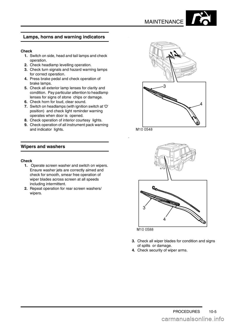
3.Check all wiper blades for condition and signs
of splits or damage.
4.Check security of wiper arms.
Page 164 of 1529

ENGINE - V8
DESCRIPTION AND OPERATION 12-2-9
Oil is drawn from the sump through a strainer and into the oil pump via the oil pick-up pipe. Pressurised oil from the
pump passes through the oil cooler (if fitted) mounted in front of the radiator and returns to the full flow oil filter
element. Oil from the filter passes into the main oil gallery and through internal drillings to the crankshaft where it is
directed to each main bearing and to the big-end bearings via numbers 1, 3 and 5 main bearings. An internal drilling
in the cylinder block directs oil to the camshaft where it passes through further internal drillings to the hydraulic
tappets, camshaft bearing journals and rocker shafts. Lubrication to the pistons, small ends and cylinder bores is by
oil grooves machined in the connecting rods and by splash.
Oil pressure switch
The oil pressure warning light switch registers low oil pressure in the main oil gallery on the outflow side of the filter.
Whilst the engine is running and oil pressure is correct, the switch is open. When the ignition is switched on or if oil
pressure drops below the pressure setting of the switch, the switch closes and the low oil pressure warning lamp
located in the instrument pack will illuminate.
Hydraulic tappets
1Clip
2Pushrod seat
3Inner sleeve
4Upper chamber5Non-return ball valve
6Spring
7Outer sleeve
8Lower chamber
The hydraulic tappet provides maintenance free, quiet operation of the valves. This is achieved by utilizing engine oil
pressure to eliminate the clearance between the rocker arms and valve stems. When the valve is closed, engine oil
pressure present in the upper chamber, passes through the non-return ball valve and into the lower chamber. When
the cam begins to lift the outer sleeve, the resistance of the valve spring, felt through the push rod and seat, causes
the tappet inner sleeve to move downwards inside the outer sleeve. This downwards movement closes the non-return
ball valve and increases the pressure in the lower chamber sufficiently to ensure that the valve is fully opened by the
push rod. As the tappet moves off the peak of the cam, the non-return ball valve opens thereby allowing the pressure
in both chambers to equalize. This ensures that the valve will be fully closed when the tappet is on the back of the
cam.
Crankcase ventilation
A positive crankcase ventilation system is used to vent crankcase gases to the air induction system. Gases are drawn
from the left hand rocker cover to a tapping in the throttle body. An oil separator is incorporated in the hose connection
stub pipe in the right hand rocker cover, gases from this connection are drawn to a tapping in the inlet manifold.
+ EMISSION CONTROL - V8, DESCRIPTION AND OPERATION, Crankcase Emission Control System.
Page 189 of 1529

ENGINE - V8
12-2-34 REPAIRS
Ring gear - starter
$% 12.53.19
Remove
1.Remove flywheel.
+ ENGINE - V8, REPAIRS, Flywheel.
2.Drill a 3 mm (0.12 in) diameter hole at root of 2
teeth.
3.Apply a cold chisel in root of one of ring gear
teeth, strike chisel with hammer to break ring
gear.
WARNING: SUITABLE EYE PROTECTION
MUST BE WORN.
4.Remove starter ring gear. Refit
1.Clean flywheel and starter ring gear.
2.Heat new starter ring gear evenly to 350°C
(660°F), indicated when the ring is a light blue
colour.
3.Locate ring gear on flywheel and press ring
gear hard against flange on flywheel.
4.Ensure ring gear is correctly seated around the
complete circumference of flywheel and allow
to cool.
5.Fit flywheel.
+ ENGINE - V8, REPAIRS, Flywheel.
Page 238 of 1529

EMISSION CONTROL - V8
DESCRIPTION AND OPERATION 17-2-5
Evaporative emission system control
diagram
1Battery
2Fuse 13 (engine compartment fusebox)
3Inertia switch
4Main relay (engine compartment fusebox)
5Engine Control Module (ECM)
6Purge Valve (black harness connector)
7Canister vent solenoid (CVS) valve – NAS
vehicles with vacuum type EVAP system leak
detection capability only8Leak detection pump – NAS vehicles with
positive pressure type EVAP system leak
detection capability only
9Fuel tank pressure sensor – NAS vehicles with
vacuum type EVAP system leak detection
capability only
10Instrument pack (MIL warning light)
M17 0210
12
3
4
5
6
7
9
8
10
Page 242 of 1529

EMISSION CONTROL - V8
DESCRIPTION AND OPERATION 17-2-9
Emission Control Systems
Engine design has evolved in order to minimise the emission of harmful by-products. Emission control systems are
fitted to Land Rover vehicles which are designed to maintain the emission levels within the legal limits pertaining for
the specified market.
Despite the utilisation of specialised emission control equipment, it is still necessary to ensure that the engine is
correctly maintained and is in good mechanical order so that it operates at its optimal condition. In particular, ignition
timing has an effect on the production of HC and NO
x emissions, with the harmful emissions rising as the ignition
timing is advanced.
CAUTION: In many countries it is against the law for a vehicle owner or an unauthorised dealer to modify or
tamper with emission control equipment. In some cases, the vehicle owner and/or the dealer may even be
liable for prosecution.
The engine management ECM is fundamental for controlling the emission control systems. In addition to controlling
normal operation, the system complies with On Board Diagnostic (OBD) system strategies. The system monitors and
reports on faults detected with ignition, fuelling and exhaust systems which cause an excessive increase in tailpipe
emissions. This includes component failures, engine misfire, catalyst damage, catalyst efficiency, fuel evaporative
loss and exhaust leaks.
When an emission relevant fault is determined, the fault condition is stored in the ECM memory. For NAS vehicles,
the MIL warning light on the instrument pack will be illuminated when the fault is confirmed. Confirmation of a fault
condition occurs if the fault is still found to be present during the driving cycle subsequent to the one when the fault
was first detected.
+ ENGINE MANAGEMENT SYSTEM - V8, DESCRIPTION AND OPERATION, Description - engine
management.
The following types of supplementary control system are used to reduce harmful emissions released into the
atmosphere from the vehicle:
1Crankcase emission control – also known as blow-by gas emissions from the engine crankcase.
2Exhaust emission control – to limit the undesirable by-products of combustion.
3Fuel vapour evaporative loss control – to restrict the emission of fuel through evaporation from the fuel
system.
4Fuel leak detection system (NAS only) – there are two types of system which may be used to check the
evaporative emission system for the presence of leaks from the fuel tank to purge valve.
aVacuum leak detection test – checks for leaks down to 1 mm (0.04 in.) in diameter.
bPositive pressure leak detection test – utilises a leak detection pump to check for leaks down to 0.5 mm (0.02
in.) in diameter.
5Secondary air injection system (Where fitted) – to reduce emissions experienced during cold starting.
Page 274 of 1529

EMISSION CONTROL - V8
DESCRIPTION AND OPERATION 17-2-41
EVAP System, Leak Detection Diagnostic (vacuum type)
The EVAP system leak detection is performed as follows:
1The ECM checks that the signal from the fuel tank pressure sensor is within the expected range. If the signal is
not within range, the leakage test will be cancelled.
2Next the purge valve is held closed and the canister vent solenoid (CVS) valve is opened to atmosphere. If the
ECM detects a rise in pressure with the valves in this condition, it indicates there is a blockage in the fuel
evaporation line between the CVS valve and the EVAP canister, or that the CVS valve is stuck in the closed
position and thus preventing normalisation of pressure in the fuel evaporation system. In this instance, the
leakage test will be cancelled.
3The CVS valve and the purge valve are both held in the closed position while the ECM checks the fuel tank
pressure sensor. If the fuel tank pressure sensor detects a decline in pressure, it indicates that the purge valve
is not closing properly and vapour is leaking past the valve seat face under the influence of the intake manifold
depression. In this instance, the leakage test will be cancelled.
4If the preliminary checks are satisfactory, a compensation measurement is determined next. Variations in fuel
level occur within the fuel tank, which will influence the pressure signal detected by the fuel tank pressure
sensor. The pressure detected will also be influenced by the rate of change in the fuel tank pressure, caused by
the rate of fuel evaporation which itself is dependent on the ambient temperature conditions. Because of these
variations, it is necessary for the ECM to evaluate the conditions prevailing at a particular instance when testing,
to ensure that the corresponding compensation factor is included in its calculations.
The CVS valve and purge valves are both closed while the ECM checks the signal from the fuel tank pressure
sensor. The rise in fuel pressure detected over a defined period is used to determine the rate of fuel evaporation
and the consequent compensation factor necessary.
5With the CVS valve still closed, the purge valve is opened. The inlet manifold depression present while the purge
valve is open, decreases EVAP system pressure and sets up a small vacuum in the fuel tank. The fuel tank
pressure sensor is monitored by the ECM and if the vacuum gradient does not increase as expected, a large
system leak is assumed by the ECM (e.g. missing or leaking fuel filler cap) and the diagnostic test is terminated.
If the EVAP canister is heavily loaded with hydrocarbons, purging may cause the air:fuel mixture to become
excessively rich, resulting in the upstream oxygen sensors requesting a leaner mix from the ECM to bring the
mixture back to the stoichiometric ideal. This may cause instability in the engine idle speed and consequently
the diagnostic test will have to be abandoned. The ECM checks the status of the upstream oxygen sensors
during the remainder of the diagnostic, to ensure the air:fuel mixture does not adversely affect the engine idle
speed.
6When the fuel tank pressure sensor detects that the required vacuum has been reached (-800 Pa), the purge
valve is closed and the EVAP system is sealed. The ECM then checks the change in the fuel tank pressure
sensor signal (diminishing vacuum) over a period of time, and if it is greater than expected (after taking into
consideration the compensation factor due to fuel evaporation within the tank, determined earlier in the
diagnostic), a leak in the EVAP system is assumed. If the condition remains, the MIL warning light will be turned
on after two drive cycles.
The decrease in vacuum pressure over the defined period must be large enough to correspond to a hole
equivalent to 1 mm (0.04 in.) diameter or greater, to be considered significant enough to warrant the activation
of an emissions system failure warning.
The diagnostic test is repeated at regular intervals during the drive cycle, when the engine is at idle condition. The
diagnostic test will not be able to be performed under the following conditions:
lDuring EVAP canister purging
lDuring fuelling adaption
lIf excess slosh in the fuel tank is detected (excess fuel vapour will be generated, invalidating the result)
Following the test, the system returns to normal purge operation after the canister vent solenoid opens. Possible
reasons for an EVAP system leak test failure are listed below:
lFuel filler not tightened or cap missing.
lSensor or actuator open circuit.
lShort circuit to vehicle supply or ground.
lEither purge or CVS valve stuck open.
lEither purge or CVS valve stuck shut or blocked pipe.
lPiping broken or not connected.
lLoose or leaking connection.
Page 355 of 1529

ENGINE MANAGEMENT SYSTEM - V8
18-2-56 DESCRIPTION AND OPERATION
Function
Input for the rough road signal is measured via pin 34 of connector C0637 of the ECM. The SLABS ECU generates
a PWM signal that varies in accordance with changing road conditions. The rough road PWM signal operates at a
frequency of 2.33 Hz ± 10%. The significance of changes in the PWM signal are shown in the following table:
The rough road signal can fail in the following ways:
lHarness or connector damage
lSLABS failure — wheel speed sensor
A rough road signal failure may be evident from the following:
lHDC / ABS warning light on
Should a malfunction of the rough road signal occur, the following fault codes may be evident and can be retrieved
by TestBook:
Hill Descent Control (HDC) signal
The ECM transmits throttle angle, engine torque, engine identification (Td5 or V8), and transmission type (automatic
or manual) data to the SLABS ECU to support the Hill Descent Control system. The information is transmitted via a
0 – 12V pulse width modulated (PWM) signal at a frequency of 179.27 Hz.
Function
The HDC signal output from the ECM is via pin 29 of connector C0636. The ECM generates a PWM signal that varies
in pulse width in accordance with changing throttle angle or engine torque. The throttle angle data is transmitted on
pulses 1, 3, 5 and 37. The engine torque data is transmitted on pulses 2,4,6 and 38. The engine and transmission
information is transmitted on pulse 39. A synchronising pulse is transmitted after every 39th pulse.
The HDC signal can fail in the following ways:
lHarness or connector damage
A HDC signal failure may be evident from the following:
lHDC / ABS warning light on
lHDC inoperative
lAudible warning
Should a malfunction of the HDC signal occur, the following fault codes may be evident and can be retrieved by
TestBook:
PWM signal Indication
<10% Electrical short circuit to ground
25% ± 5 % Smooth road
50% ± 5 % SLABS error
75% ± 5% Rough road
>90% Electrical short circuit to battery voltage
P Code J2012 Description Land Rover Description
P1590 ABS rough road signal circuit malfunction Hardware is OK, but SLABS ECU is sending an error
signal
P1591 ABS rough road signal circuit low Signal from SLABS ECU short circuit to earth
P1592 ABS rough road signal circuit high Signal from SLABS ECU short circuit to vehicle battery
supply
P Code J2012 Description Land Rover Description
P1663 Throttle angle/Torque signal circuit malfunction SLABS HDC link open circuit
P1664 Throttle angle/Torque signal circuit low SLABS HDC link short circuit to ground
P1665 Throttle angle/Torque signal circuit high SLABS HDC link short circuit to battery voltage
Page 553 of 1529

TRANSFER BOX - LT230SE
41-28 REPAIRS
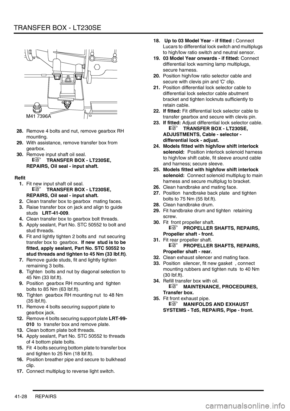
28.Remove 4 bolts and nut, remove gearbox RH
mounting.
29.With assistance, remove transfer box from
gearbox.
30.Remove input shaft oil seal.
+ TRANSFER BOX - LT230SE,
REPAIRS, Oil seal - input shaft.
Refit
1.Fit new input shaft oil seal.
+ TRANSFER BOX - LT230SE,
REPAIRS, Oil seal - input shaft.
2.Clean transfer box to gearbox mating faces.
3.Raise transfer box on jack and align to guide
studs LRT-41-009.
4.Clean transfer box to gearbox bolt threads.
5.Apply sealant, Part No. STC 50552 to bolt and
stud threads.
6.Fit and lightly tighten 2 bolts and nut securing
transfer box to gearbox. If new stud is to be
fitted, apply sealant, Part No. STC 50552 to
stud threads and tighten to 45 Nm (33 lbf.ft).
7.Remove guide studs, fit and lightly tighten
remaining 3 bolts.
8.Tighten bolts and nut by diagonal selection to
45 Nm (33 lbf.ft).
9.Position gearbox RH mounting and tighten
bolts to 85 Nm (63 lbf.ft).
10.Tighten gearbox RH mounting nut to 48 Nm
(35 lbf.ft).
11.Remove 4 bolts securing support plate to
gearbox jack.
12.Remove 4 bolts securing support plate LRT-99-
010 to transfer box and remove plate.
13.Clean bottom plate bolt threads.
14.Apply sealant, Part No. STC 50552 to threads
of 4 bottom plate bolts.
15.Fit 4 bolts securing bottom plate to transfer box
and tighten to 25 Nm (18 lbf.ft).
16.Position breather pipe and secure to bulkhead
clip.
17.Connect multiplug to reverse light switch. 18. Up to 03 Model Year - if fitted : Connect
Lucars to differential lock switch and multiplugs
to high/low ratio switch and neutral sensor.
19. 03 Model Year onwards - if fitted: Connect
differential lock warning lamp multiplugs,
secure harness.
20.Position high/low ratio selector cable and
secure with clevis pin and 'C' clip.
21.Position differential lock selector cable to
differential lock selector cable abutment
bracket and tighten locknuts sufficiently to
retain cable.
22. If fitted: Fit differential lock selector cable to
transfer gearbox and secure with clevis pin.
23. If fitted: Adjust differential lock selector cable.
+ TRANSFER BOX - LT230SE,
ADJUSTMENTS, Cable - selector -
differential lock - adjust.
24. Models fitted with high/low shift interlock
solenoid: Position interlock solenoid harness
to high/low shift cable, fit sleeve around cable
and harness; secure sleeve.
25. Models fitted with high/low shift interlock
solenoid: Connect solenoid multiplug to main
harness and secure multiplug to bracket.
26.Clean handbrake and mating face.
27.Position handbrake back plate and tighten
bolts to 75 Nm (55 lbf.ft).
28.Clean handbrake drum.
29.Fit handbrake drum and tighten retaining
screw.
30.Fit front propeller shaft.
+ PROPELLER SHAFTS, REPAIRS,
Propeller shaft - front.
31.Fit rear propeller shaft.
+ PROPELLER SHAFTS, REPAIRS,
Propeller shaft - rear.
32.Clean exhaust silencer and mating face.
33.Position silencer, fit new gasket , connect
mounting rubbers and tighten nuts to 40 Nm
(30 lbf.ft).
34.Refill transfer box with oil.
+ MAINTENANCE, PROCEDURES,
Transfer box.
35.Fit front exhaust pipe.
+ MANIFOLDS AND EXHAUST
SYSTEMS - Td5, REPAIRS, Pipe - front.