differential LAND ROVER DISCOVERY 1999 Owners Manual
[x] Cancel search | Manufacturer: LAND ROVER, Model Year: 1999, Model line: DISCOVERY, Model: LAND ROVER DISCOVERY 1999Pages: 1529, PDF Size: 34.8 MB
Page 684 of 1529

FRONT AXLE
REPAIRS 54-5
REPAIRS
Differential - assembly
$% 54.10.01
Remove
1.Raise front of vehicle.
WARNING: Do not work on or under a
vehicle supported only by a jack. Always
support the vehicle on safety stands.
2.Remove front road wheels.
3.Drain oil from differential.
+ MAINTENANCE, PROCEDURES,
Front and rear axle.
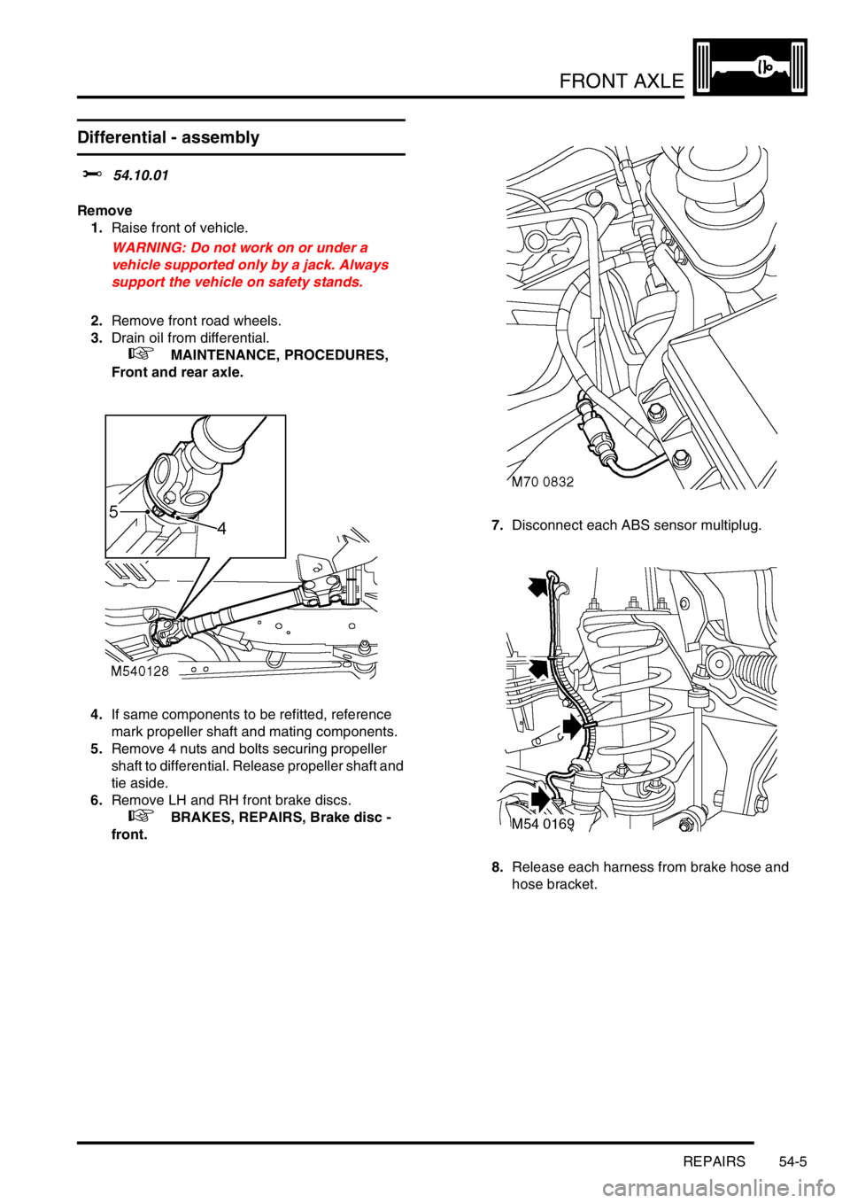
4.If same components to be refitted, reference
mark propeller shaft and mating components.
5.Remove 4 nuts and bolts securing propeller
shaft to differential. Release propeller shaft and
tie aside.
6.Remove LH and RH front brake discs.
+ BRAKES, REPAIRS, Brake disc -
front.7.Disconnect each ABS sensor multiplug.
8.Release each harness from brake hose and
hose bracket.
Page 685 of 1529

FRONT AXLE
54-6 REPAIRS
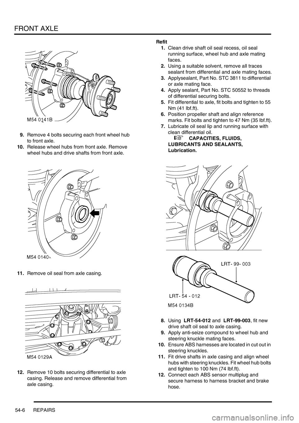
9.Remove 4 bolts securing each front wheel hub
to front axle.
10.Release wheel hubs from front axle. Remove
wheel hubs and drive shafts from front axle.
11.Remove oil seal from axle casing.
12.Remove 10 bolts securing differential to axle
casing. Release and remove differential from
axle casing.Refit
1.Clean drive shaft oil seal recess, oil seal
running surface, wheel hub and axle mating
faces.
2.Using a suitable solvent, remove all traces
sealant from differential and axle mating faces.
3.Applysealant, Part No. STC 3811 to differential
or axle mating face.
4.Apply sealant, Part No. STC 50552 to threads
of differential securing bolts.
5.Fit differential to axle, fit bolts and tighten to 55
Nm (41 lbf.ft).
6.Position propeller shaft and align reference
marks. Fit bolts and tighten to 47 Nm (35 lbf.ft).
7.Lubricate oil seal lip and running surface with
clean differential oil.
+ CAPACITIES, FLUIDS,
LUBRICANTS AND SEALANTS,
Lubrication.
8.Using LRT-54-012 and LRT-99-003, fit new
drive shaft oil seal to axle casing.
9.Apply anti-seize compound to wheel hub and
steering knuckle mating faces.
10.Ensure ABS harnesses are located in cut out in
steering knuckles.
11.Fit drive shafts in axle casing and align wheel
hubs with steering knuckles. Fit wheel hub bolts
and tighten to 100 Nm (74 lbf.ft).
12.Connect each ABS sensor multiplug and
secure harness to harness bracket and brake
hose.
Page 686 of 1529

FRONT AXLE
REPAIRS 54-7
13.Fit front brake discs.
+ BRAKES, REPAIRS, Brake disc -
front.
14.Fit front road wheels and tighten nuts to 140
Nm (103 lbf.ft).
15.Remove stand(s) and lower vehicle.
16.Fill differential with oil.
+ MAINTENANCE, PROCEDURES,
Front and rear axle.
Seal - differential pinion
$% 54.10.20
Remove
1.Raise front of vehicle.
WARNING: Do not work on or under a
vehicle supported only by a jack. Always
support the vehicle on safety stands.
2.Reference mark front propeller shaft for
reassembly.
3.Remove 4 nuts and bolts securing propeller
shaft to differential. Release propeller shaft and
tie aside.
4.Using LRT-51-003 to restrain pinion flange,
remove bolt and washer securing pinion flange.
Remove pinion flange.
5.Position container to catch oil spillage.
Page 687 of 1529

FRONT AXLE
54-8 REPAIRS
6.Using a suitable lever, remove pinion oil seal.
Take care to avoid damage to oil seal
recess.Refit
1.Clean pinion oil seal recess and pinion flange.
2.Lubricate pinion oil seal lip with clean
differential oil.
+ CAPACITIES, FLUIDS,
LUBRICANTS AND SEALANTS,
Lubrication.
3.Using LRT-51-010 , fit pinion oil seal.
4.Fit pinion flange and securing bolt and washer.
Using LRT- 51-003, restrain pinion flange and
tighten pinion flange bolt to 100 Nm (74 lbf.ft).
5.Position propeller shaft and align reference
marks. Fit nuts and bolts and tighten to 47 Nm
(35 lbf.ft).
6.Remove stand(s) and lower vehicle.
7.Check differential oil level.
+ MAINTENANCE, PROCEDURES,
Front and rear axle.
Page 689 of 1529

FRONT AXLE
54-10 REPAIRS
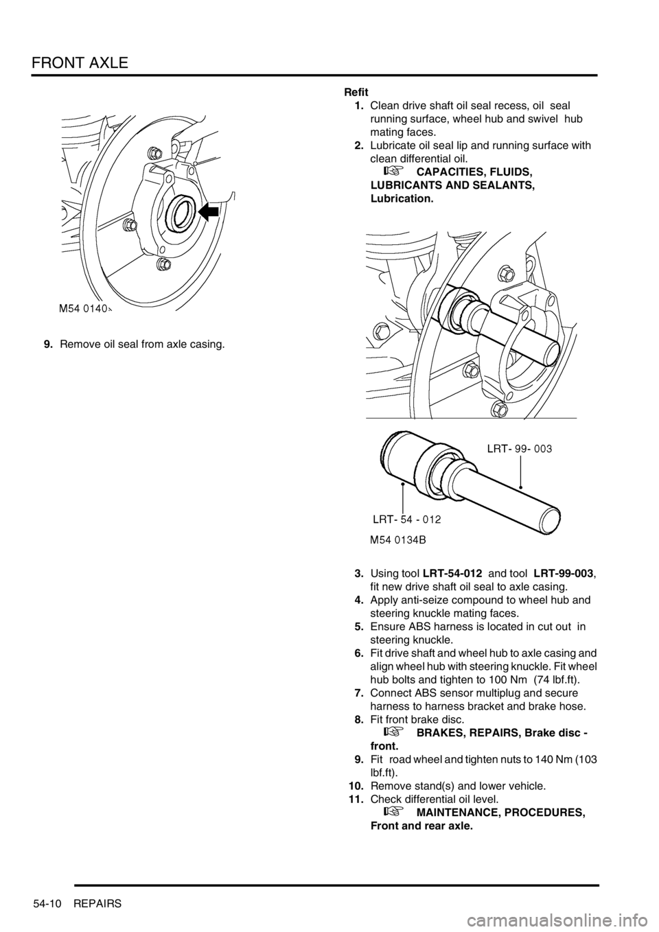
9.Remove oil seal from axle casing.Refit
1.Clean drive shaft oil seal recess, oil seal
running surface, wheel hub and swivel hub
mating faces.
2.Lubricate oil seal lip and running surface with
clean differential oil.
+ CAPACITIES, FLUIDS,
LUBRICANTS AND SEALANTS,
Lubrication.
3.Using tool LRT-54-012 and tool LRT-99-003,
fit new drive shaft oil seal to axle casing.
4.Apply anti-seize compound to wheel hub and
steering knuckle mating faces.
5.Ensure ABS harness is located in cut out in
steering knuckle.
6.Fit drive shaft and wheel hub to axle casing and
align wheel hub with steering knuckle. Fit wheel
hub bolts and tighten to 100 Nm (74 lbf.ft).
7.Connect ABS sensor multiplug and secure
harness to harness bracket and brake hose.
8.Fit front brake disc.
+ BRAKES, REPAIRS, Brake disc -
front.
9.Fit road wheel and tighten nuts to 140 Nm (103
lbf.ft).
10.Remove stand(s) and lower vehicle.
11.Check differential oil level.
+ MAINTENANCE, PROCEDURES,
Front and rear axle.
Page 779 of 1529

FRONT SUSPENSION
60-34 REPAIRS
11.Position the wheel hub and drive shaft on a
press, place supports beneath the wheel studs
and press the drive shaft from the wheel hub.
12.Remove drive shaft oil seal from axle casing. Refit
1.Clean drive shaft oil seal recess, drive shaft
splines, oil seal running surface, wheel hub
and steering knuckle mating faces, ABS
sensor and sensor recess.
2.Lubricate lip of new drive shaft oil seal and
running surface on drive shaft with clean
differential oil.
+ CAPACITIES, FLUIDS,
LUBRICANTS AND SEALANTS,
Lubrication.
3.Use tool LRT-51-012 to fit new drive shaft oil
seal to axle casing.
4.Fit drive shaft to axle casing.
5.Apply anti-seize compound to wheel hub and
steering knuckle mating face.
M51 0057
Page 837 of 1529

REAR SUSPENSION
64-28 REPAIRS
10.Position the wheel hub and drive shaft on a
press, place supports beneath the wheel studs
and press the drive shaft from the wheel hub.
Refit
1.Clean drive shaft splines, wheel hub and axle
mating faces, ABS sensor and sensor recess.
2.Fit drive shaft to axle casing.
3.Lubricate new bearing hub 'O' ring with clean
differential oil.
+ CAPACITIES, FLUIDS,
LUBRICANTS AND SEALANTS,
Lubrication.
4.Fit 'O' ring to wheel hub.
5.Apply a 3 mm (0.125 in) wide bead of sealant,
Part No. STC 50554 around drive shaft
circumference as illustrated.
6.Fit wheel hub to drive shaft and align to axle.
The sealant will smear along the length of the
splines as the wheel hub is fitted to the drive
shaft.
7.Fit bolts securing wheel hub to axle and tighten
to 100 Nm (74 lbf.ft).
8.Fit new drive shaft nut and lightly tighten.
9.Fit rear brake disc.
+ BRAKES, REPAIRS, Brake disc -
rear.
10.With an assistant depressing the brake pedal,
tighten drive shaft nut to 490 Nm (360 lbf.ft).
Stake drive shaft nut. The drive shaft nut
must be tightened before the sealant has
cured.
11.Connect ABS sensor multiplug and secure
harness to harness bracket and brake hose.
12.Fit road wheel and tighten nuts to 140 Nm (103
lbf.ft).
13.Remove stand(s) and lower vehicle.
M51 0057
M51 0058
Page 856 of 1529

BRAKES
DESCRIPTION AND OPERATION 70-3
1ABS sensor
2ABS modulator
3Return pump relay
4SLABS ECU
5Brake lamp relay
6Centre high mounted stop lamp
7LH brake lamp
8RH brake lamp
9Instrument pack10Body control unit
11Reverse lamp switch (manual gearbox)
12Diagnostic socket
13HDC switch
14Transmission high/low switch
15Centre differential lock switch
16Engine control module
17Battery power supply
18Ignition power supply
Page 861 of 1529

BRAKES
70-8 DESCRIPTION AND OPERATION
Brakes on
When the brake pedal is pressed, the input push rod and the piston initially move forward in the valve body. The valve
body and output rod then move with the input rod, against resistance from the return spring, to transmit the brake
pedal force to the master cylinder assembly.
During the initial movement of the piston, the valve, assisted by the valve spring, moves with the piston and closes
the vacuum port to isolate the chambers at the rear of the diaphragms from the vacuum source. Further movement
of the input push rod causes the piston to move away from the valve and open the air inlet port. This allows a restricted
flow of filtered ambient air through the air inlet port, which creates a servo pressure in the chambers at the rear of the
diaphragms. Force from the resultant pressure differential across the diaphragms is transmitted through the valve
body to the output push rod, augmenting the pressure being applied by the brake pedal. The force produced by the
diaphragms, in proportion to the input force, i.e. the boost ratio, is 5.6 : 1. The boost ratio remains constant, as the
input force from the brake pedal increases, until the limit of assistance is reached when servo pressure is equal to
ambient pressure.
Brakes held on
When the brake pedal effort is constant, opposing pressures cause the reaction disc to extrude onto the ratio disc,
which moves the piston against the valve to close the air inlet port. This prevents any further increase in servo
pressure and maintains a constant output force to the master cylinder assembly.
Brakes released
When the brake pedal is released, the input rod spring moves the input rod and piston rearwards within the valve body
to close the air inlet port and open the vacuum port. The air from the chambers at the rear of the diaphragms is then
evacuated, through the vacuum port and the chambers at the front of the diaphragms, to restore a partial vacuum in
all four chambers. Simultaneously, the return spring moves the valve body, diaphragms, output rod and input rod
rearwards to return them to their brakes off position.
Page 871 of 1529

BRAKES
70-18 DESCRIPTION AND OPERATION
The SLABS ECU continually calculates vehicle speed using the wheel speed inputs from all four ABS sensors. The
calculated vehicle speed is then used as a reference against which individual wheel speeds are monitored for
unacceptable acceleration or deceleration. The ABS sensor inputs are also used by the SLABS ECU to detect vehicle
deceleration rate, vehicle cornering rate and rough terrain.
The engaged forward gear and (on manual gearbox models) the clutch status are computed from the engine data
input, the engine speed input and vehicle speed. Reverse gear status is provided by an input from the reverse lamp
switch (manual gearbox models) or the BCU (automatic gearbox models). On automatic models, the BCU also
provides the neutral selected input.
In addition to controlling the brake related functions, the SLABS ECU:
lControls the operation of the self levelling suspension (SLS) system (where fitted).
+ REAR SUSPENSION, DESCRIPTION AND OPERATION, Description.
lOn V8 models, outputs a rough road signal to the ECM when traversing rough terrain.
lOutputs a vehicle speed signal.
The vehicle speed signal is output to the following systems (where fitted):
lActive Cornering Enhancement.
+ FRONT SUSPENSION, DESCRIPTION AND OPERATION, Description - ACE.
lAir conditioning.
+ AIR CONDITIONING, DESCRIPTION AND OPERATION, Description.
lCruise control.
+ ENGINE MANAGEMENT SYSTEM - Td5, DESCRIPTION AND OPERATION, Description.
+ ENGINE MANAGEMENT SYSTEM - V8, DESCRIPTION AND OPERATION, Description - engine
management.
lEngine management.
+ ENGINE MANAGEMENT SYSTEM - Td5, DESCRIPTION AND OPERATION, Description.
+ ENGINE MANAGEMENT SYSTEM - V8, DESCRIPTION AND OPERATION, Description - engine
management.
lIn-car entertainment.
+ IN CAR ENTERTAINMENT, DESCRIPTION AND OPERATION, Description.
lInstrument pack.
+ INSTRUMENTS, DESCRIPTION AND OPERATION, Description.
5 Front right inlet solenoid valve Output
6 Shuttle valve switches Input
7 Rear left outlet solenoid valve Output
8 Rear left inlet solenoid valve Output
9 Centre differential lock switch Input
10 Rear right outlet solenoid valve Output
11 Rear right inlet solenoid valve Output
12 Brake lamp relay Output
15 Return pump relay Output
C0655
7 Audible warning Output
10 Engine speed Input
Connector and pins not listed are either not used or used by the self levelling suspension system.
+ REAR SUSPENSION, DESCRIPTION AND OPERATION, Description.
Connector/Pin
No.Description Input/Output