alternator LAND ROVER DISCOVERY 1999 User Guide
[x] Cancel search | Manufacturer: LAND ROVER, Model Year: 1999, Model line: DISCOVERY, Model: LAND ROVER DISCOVERY 1999Pages: 1529, PDF Size: 34.8 MB
Page 200 of 1529
ENGINE - V8
OVERHAUL 12-2-45
OVERHAUL
Gasket - inlet manifold
$% 30.15.08.01
Disassembly
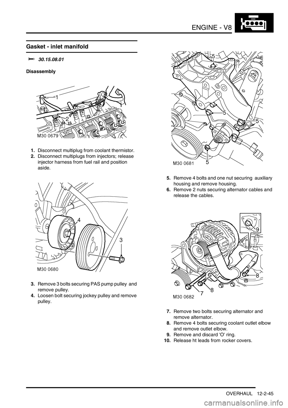
1.Disconnect multiplug from coolant thermistor.
2.Disconnect multiplugs from injectors; release
injector harness from fuel rail and position
aside.
3.Remove 3 bolts securing PAS pump pulley and
remove pulley.
4.Loosen bolt securing jockey pulley and remove
pulley. 5.Remove 4 bolts and one nut securing auxiliary
housing and remove housing.
6.Remove 2 nuts securing alternator cables and
release the cables.
7.Remove two bolts securing alternator and
remove alternator.
8.Remove 4 bolts securing coolant outlet elbow
and remove outlet elbow.
9.Remove and discard 'O' ring.
10.Release ht leads from rocker covers.
Page 202 of 1529
ENGINE - V8
OVERHAUL 12-2-47
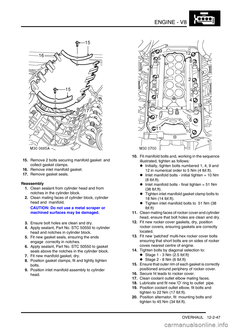
15.Remove 2 bolts securing manifold gasket and
collect gasket clamps.
16.Remove inlet manifold gasket.
17.Remove gasket seals.
Reassembly
1.Clean sealant from cylinder head and from
notches in the cylinder block.
2.Clean mating faces of cylinder block, cylinder
head and manifold.
CAUTION: Do not use a metal scraper or
machined surfaces may be damaged.
3.Ensure bolt holes are clean and dry.
4.Apply sealant, Part No. STC 50550 to cylinder
head and notches in cylinder block.
5.Fit new gasket seals, ensuring the ends
engage correctly in notches.
6.Apply sealant, Part No. STC 50550 to gasket
seals above the notches in the cylinder block.
7.Fit new manifold gasket, dry.
8.Position gasket clamps, fit and lightly tighten
bolts.
9.Position inlet manifold assembly to cylinder
head. 10.Fit manifold bolts and, working in the sequence
illustrated, tighten as follows:
lInitially, tighten bolts numbered 1, 4, 9 and
12 in numerical order to 5 Nm (4 lbf.ft).
lInlet manifold bolts - initial tighten = 10 Nm
(8 lbf.ft).
lInlet manifold bolts - final tighten = 51 Nm
(38 lbf.ft).
lTighten inlet manifold gasket clamp bolts to
18 Nm (14 lbf.ft).
lTighten inlet manifold bolts to 51 Nm (38
lbf.ft)
11.Clean mating faces of rocker cover and cylinder
head, ensure that bolt holes are clean and dry.
12.Fit new rocker cover gaskets, dry, position
rocker covers, ensuring gaskets are correctly
located.
13.Fit new 'patched' multi-hex rocker cover bolts
ensuring that short bolts are on sides of rocker
coves nearest centre of engine.
14.Tighten bolts by diagonal selection to:
lStage 1 - 3 Nm (2.5 lbf.ft)
lStage 2 - 8 Nm (6 lbf.ft)
15.Ensure that outer rim of each gasket is correctly
positioned around periphery of rocker cover.
16.Secure ht leads to rocker cover.
17.Clean coolant outlet elbow mating faces.
18.Lubricate and fit new 'O' ring to outlet pipe.
19.Position coolant outlet elbow, fit bolts and
tighten to 22 Nm (17 lbf.ft).
20.Position alternator, fit mounting bolts and
tighten to 45 Nm (34 lbf.ft).
Page 203 of 1529
ENGINE - V8
12-2-48 OVERHAUL
21.Position alternator cables and tighten terminal
B+ to 18 Nm (13 lbf.ft) and terminal D+ to 5 Nm
(3.5 lbf.ft).
22.Position auxiliary housing, fit bolts and tighten
to 40 Nm (30 lbf.ft). Fit nut and tighten to 22 Nm
(17 lbf.ft).
23.Clean jockey pulley mating faces.
24.Position jockey pulley and tighten bolt to 50 Nm
(37 lbf.ft).
25.Clean PAS pump pulley mating faces.
26.Position PAS pump pulley, fit bolts and tighten
to 22 Nm (17 lbf.ft).
27.Secure injector harness and connect injector
multiplugs.
28.Connect multiplug to coolant thermistor.
Gasket - exhaust manifold
$% 30.15.12.01
Disassembly
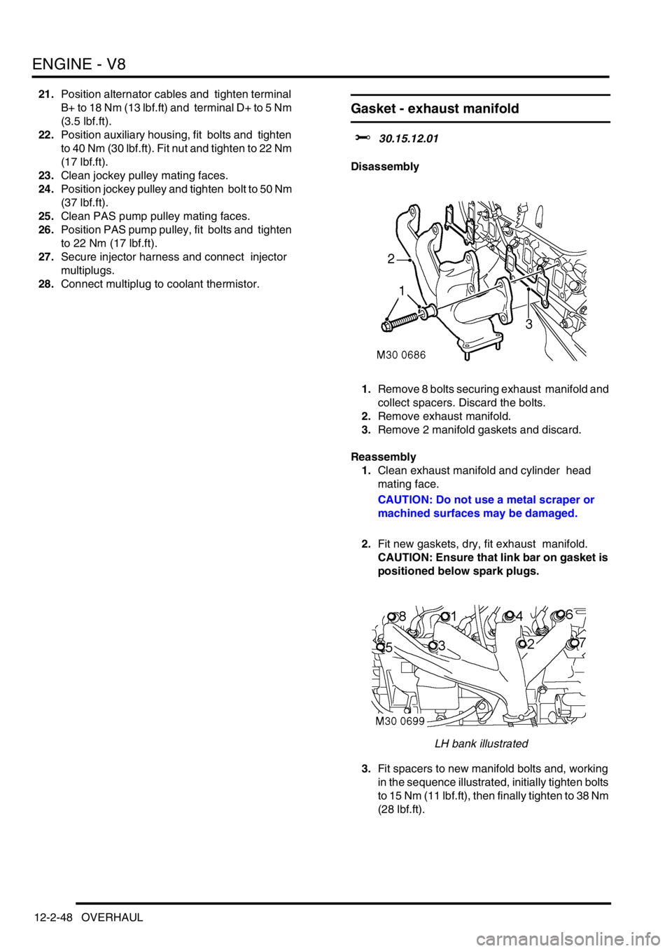
1.Remove 8 bolts securing exhaust manifold and
collect spacers. Discard the bolts.
2.Remove exhaust manifold.
3.Remove 2 manifold gaskets and discard.
Reassembly
1.Clean exhaust manifold and cylinder head
mating face.
CAUTION: Do not use a metal scraper or
machined surfaces may be damaged.
2.Fit new gaskets, dry, fit exhaust manifold.
CAUTION: Ensure that link bar on gasket is
positioned below spark plugs.
LH bank illustrated
3.Fit spacers to new manifold bolts and, working
in the sequence illustrated, initially tighten bolts
to 15 Nm (11 lbf.ft), then finally tighten to 38 Nm
(28 lbf.ft).
Page 216 of 1529
ENGINE - V8
OVERHAUL 12-2-61
Gasket - cylinder head
$% 12.29.02.01
Disassembly
1.Remove inlet manifold gasket.
+ ENGINE - V8, OVERHAUL, Gasket -
inlet manifold.
2. RH cylinder head: Remove auxiliary drive belt
tensioner.
3. RH cylinder head: Remove bolts securing
alternator mounting bracket and remove
bracket.
4.Noting their fitted order, disconnect ht leads
from spark plugs.
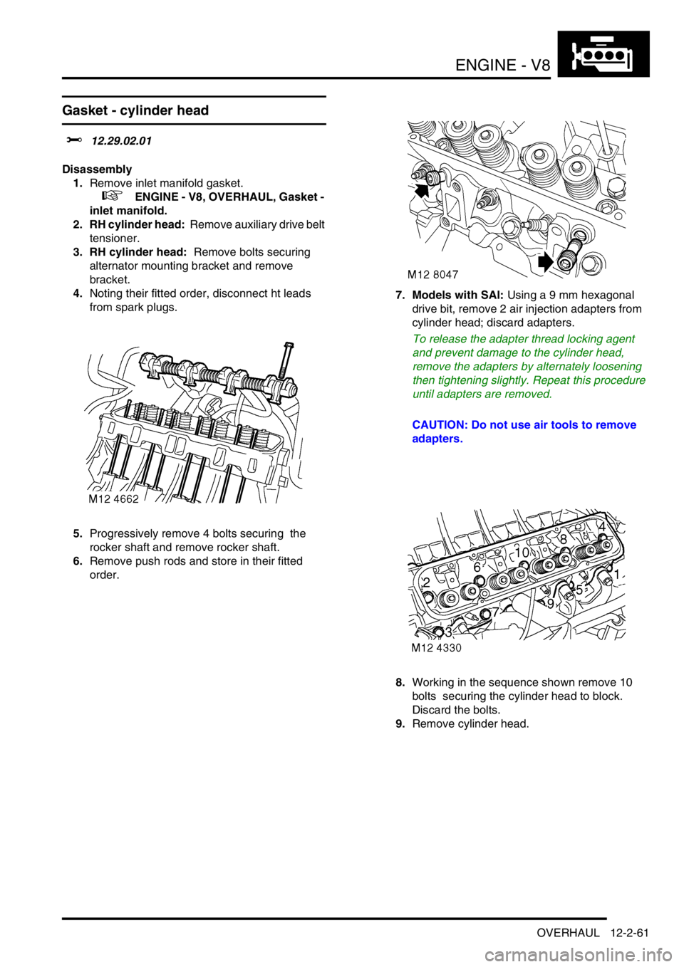
5.Progressively remove 4 bolts securing the
rocker shaft and remove rocker shaft.
6.Remove push rods and store in their fitted
order. 7. Models with SAI: Using a 9 mm hexagonal
drive bit, remove 2 air injection adapters from
cylinder head; discard adapters.
To release the adapter thread locking agent
and prevent damage to the cylinder head,
remove the adapters by alternately loosening
then tightening slightly. Repeat this procedure
until adapters are removed.
CAUTION: Do not use air tools to remove
adapters.
8.Working in the sequence shown remove 10
bolts securing the cylinder head to block.
Discard the bolts.
9.Remove cylinder head.
Page 217 of 1529
ENGINE - V8
12-2-62 OVERHAUL
10.Remove cylinder head gasket.
CAUTION: Support both ends of cylinder
head on blocks of wood.
Inspect
1.Clean mating faces of cylinder block and head
using suitable gasket removal spray and a
plastic scraper, ensure that bolt holes in block
are clean and dry.
CAUTION: Do not use a metal scraper or
machined surfaces may be damaged.
2.Check head and block faces for warping and
pitting.
lMaximum cylinder head warp = 0.05 mm
(0.002 in).
Note: Cylinder head can be refaced to 0.50
mm (0.02 in) maximum below head height –
See cylinder head overhaul.
3. Models with SAI: Using a 5/8 in x 20 TPI (
threads per inch) UNF tap having a class 2A
thread, remove deposits from secondary air
injection adapter tappings in cylinder head.
CAUTION: Ensure that tap used has 20 TPI.Reassembly
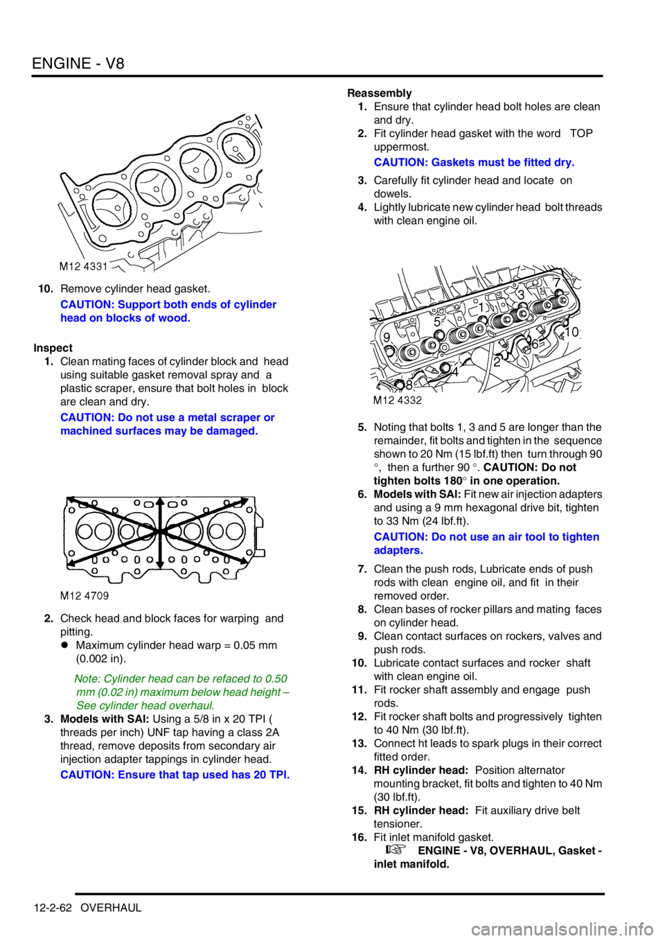
1.Ensure that cylinder head bolt holes are clean
and dry.
2.Fit cylinder head gasket with the word TOP
uppermost.
CAUTION: Gaskets must be fitted dry.
3.Carefully fit cylinder head and locate on
dowels.
4.Lightly lubricate new cylinder head bolt threads
with clean engine oil.
5.Noting that bolts 1, 3 and 5 are longer than the
remainder, fit bolts and tighten in the sequence
shown to 20 Nm (15 lbf.ft) then turn through 90
°, then a further 90 °. CAUTION: Do not
tighten bolts 180° in one operation.
6. Models with SAI: Fit new air injection adapters
and using a 9 mm hexagonal drive bit, tighten
to 33 Nm (24 lbf.ft).
CAUTION: Do not use an air tool to tighten
adapters.
7.Clean the push rods, Lubricate ends of push
rods with clean engine oil, and fit in their
removed order.
8.Clean bases of rocker pillars and mating faces
on cylinder head.
9.Clean contact surfaces on rockers, valves and
push rods.
10.Lubricate contact surfaces and rocker shaft
with clean engine oil.
11.Fit rocker shaft assembly and engage push
rods.
12.Fit rocker shaft bolts and progressively tighten
to 40 Nm (30 lbf.ft).
13.Connect ht leads to spark plugs in their correct
fitted order.
14. RH cylinder head: Position alternator
mounting bracket, fit bolts and tighten to 40 Nm
(30 lbf.ft).
15. RH cylinder head: Fit auxiliary drive belt
tensioner.
16.Fit inlet manifold gasket.
+ ENGINE - V8, OVERHAUL, Gasket -
inlet manifold.
Page 335 of 1529
ENGINE MANAGEMENT SYSTEM - V8
18-2-36 DESCRIPTION AND OPERATION
Idle Air Control Valve (IACV) (C0641)
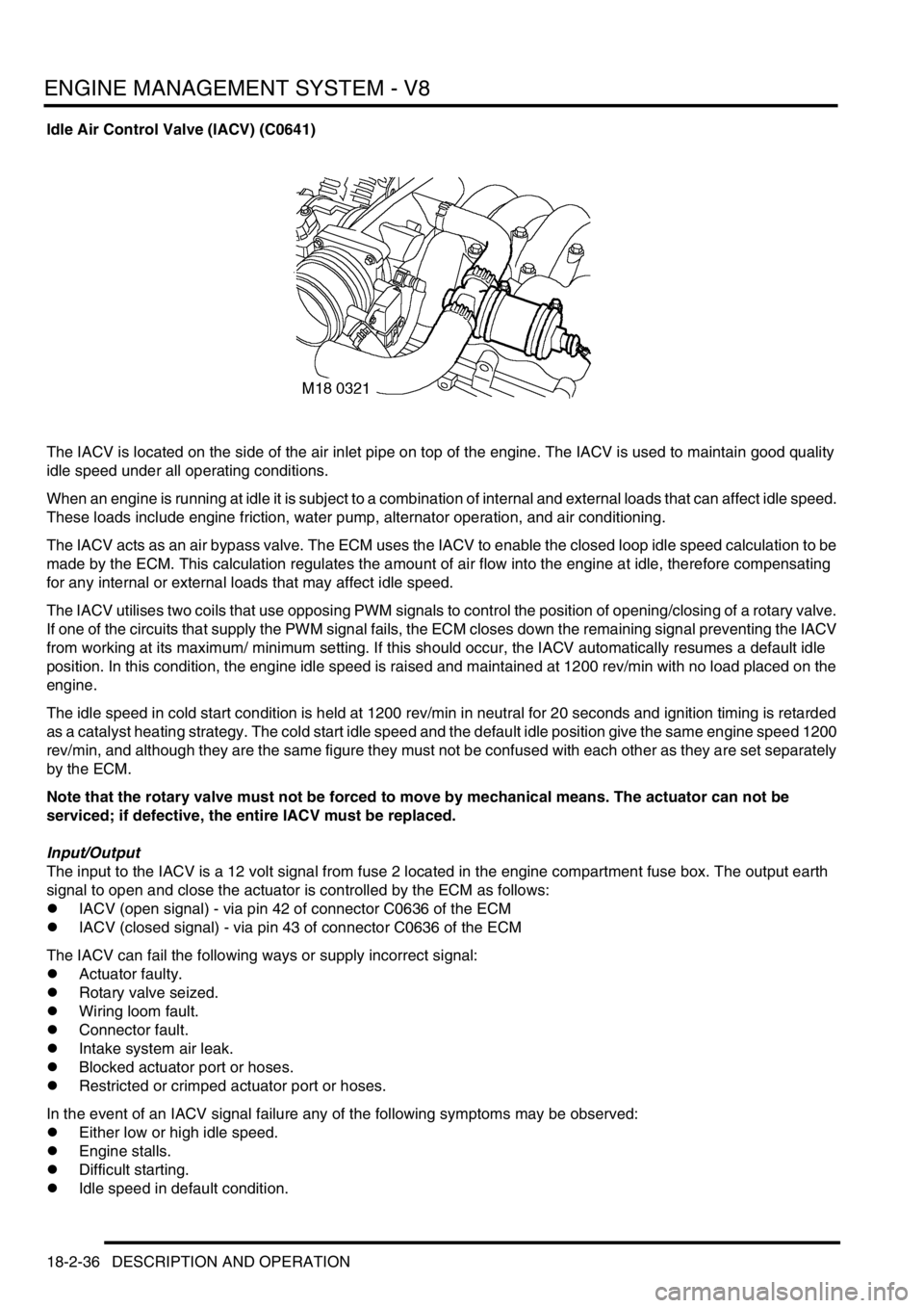
The IACV is located on the side of the air inlet pipe on top of the engine. The IACV is used to maintain good quality
idle speed under all operating conditions.
When an engine is running at idle it is subject to a combination of internal and external loads that can affect idle speed.
These loads include engine friction, water pump, alternator operation, and air conditioning.
The IACV acts as an air bypass valve. The ECM uses the IACV to enable the closed loop idle speed calculation to be
made by the ECM. This calculation regulates the amount of air flow into the engine at idle, therefore compensating
for any internal or external loads that may affect idle speed.
The IACV utilises two coils that use opposing PWM signals to control the position of opening/closing of a rotary valve.
If one of the circuits that supply the PWM signal fails, the ECM closes down the remaining signal preventing the IACV
from working at its maximum/ minimum setting. If this should occur, the IACV automatically resumes a default idle
position. In this condition, the engine idle speed is raised and maintained at 1200 rev/min with no load placed on the
engine.
The idle speed in cold start condition is held at 1200 rev/min in neutral for 20 seconds and ignition timing is retarded
as a catalyst heating strategy. The cold start idle speed and the default idle position give the same engine speed 1200
rev/min, and although they are the same figure they must not be confused with each other as they are set separately
by the ECM.
Note that the rotary valve must not be forced to move by mechanical means. The actuator can not be
serviced; if defective, the entire IACV must be replaced.
Input/Output
The input to the IACV is a 12 volt signal from fuse 2 located in the engine compartment fuse box. The output earth
signal to open and close the actuator is controlled by the ECM as follows:
lIACV (open signal) - via pin 42 of connector C0636 of the ECM
lIACV (closed signal) - via pin 43 of connector C0636 of the ECM
The IACV can fail the following ways or supply incorrect signal:
lActuator faulty.
lRotary valve seized.
lWiring loom fault.
lConnector fault.
lIntake system air leak.
lBlocked actuator port or hoses.
lRestricted or crimped actuator port or hoses.
In the event of an IACV signal failure any of the following symptoms may be observed:
lEither low or high idle speed.
lEngine stalls.
lDifficult starting.
lIdle speed in default condition.
Page 381 of 1529

ENGINE MANAGEMENT SYSTEM - V8
18-2-82 REPAIRS
Sensor - engine coolant temperature
(ECT)
$% 18.30.10
Remove
1.Release turnbuckles and remove battery cover.
2.Disconnect battery earth lead.
3.Remove auxiliary drive belt.
+ CHARGING AND STARTING,
REPAIRS, Belt - auxiliary drive.
4.Remove 2 bolts securing alternator, release
alternator from support bracket and position
aside. 5.Disconnect multiplug from ECT sensor.
6.Remove sensor from inlet manifold and discard
sealing washer.
Refit
1.Clean sealant from threads in manifold.
2.Apply sealant, Part No. STC 50552 to sensor
threads.
3.Fit new sealing washer to ECT sensor and
tighten sensor to 10 Nm (7 lbf.ft).
4.Connect multiplug to ECT sensor.
5.Position alternator, fit bolts and tighten to 45
Nm (33 lbf.ft).
6.Fit auxiliary drive belt.
+ CHARGING AND STARTING,
REPAIRS, Belt - auxiliary drive.
7.Top up cooling system.
8.Connect battery earth lead.
9.Fit battery cover and secure with fixings.
Page 446 of 1529

MANIFOLDS AND EXHAUST SYSTEMS - V8
REPAIRS 30-2-11
5.Remove 3 bolts securing ACE pump, release
pump and position aside.
6.Remove 2 bolts securing alternator and
remove alternator. 7.Remove 3 bolts securing PAS pump pulley and
remove pulley.
8.Remove jockey pulley.
9.Position tray to catch spillage, release PAS
pump high pressure pipe.
CAUTION: Always fit plugs to open
connections to prevent contamination.
10.Remove bolt securing oil cooling pipe and
release bracket from auxiliary housing.
11.Remove two bolts securing PAS pump.
12.Remove 5 bolts and one nut securing auxiliary
housing. Pull housing forward, release PAS
pump and remove housing.
Page 448 of 1529

MANIFOLDS AND EXHAUST SYSTEMS - V8
REPAIRS 30-2-13
20.Remove inlet manifold gasket.
21.Remove gasket seals.
Refit
1.Clean all traces of sealant from cylinder head
and cylinder block notches.
2.Clean mating faces of cylinder block, cylinder
head and inlet manifold.
3.Apply sealant, Part No. STC 50550 to cylinder
head and cylinder block notches.
4.Fit new gasket seals, ensuring ends engage
correctly in notches.
5.Fit new inlet manifold gasket.
6.Position gasket clamps and fit bolts, but do not
tighten at this stage.
7.Position inlet manifold to engine. Fit manifold
bolts and, working in the sequence shown,
tighten bolts initially to 10 Nm (7 lbf.ft) then to
51 Nm (38 lbf.ft).
8.Tighten gasket clamp bolts to 18 Nm (13 lbf.ft).
9.Connect fuel pipe.
10.Clean top hose outlet pipe mating faces.
11.Fit new 'O' ring to outlet pipe.
12.Position outlet pipe, fit bolts and tighten to 22
Nm (16 lbf.ft).
13.Position alternator, fit bolts and tighten to 45
Nm (33 lbf.ft).
14.Position PAS pump to auxiliary housing and
locate housing on engine. Fit bolts and tighten
to 40 Nm (30 lbf.ft).15.Fit and tighten auxiliary housing nut to 10 Nm (7
lbf.ft).
16.Fit bolts securing PAS pump and tighten to 22
Nm (16 lbf.ft).
17.Position oil cooling pipe bracket fit bolt and
tighten to 22 Nm (16 lbf.ft).
18.Fit and tighten PAS pump high pressure pipe.
19.Position jockey pulley and tighten bolt to 50 Nm
(37 lbf.ft).
20.Clean PAS pump pulley mating faces.
21.Position PAS pump pulley, fit bolts and tighten
to 22 Nm (16 lbf.ft).
22.Clean ACE pump dowels and dowel holes.
23.Position ACE pump, fit bolts and tighten to 22
Nm (16 lbf.ft).
24.Fit auxiliary drive belt.
+ CHARGING AND STARTING,
REPAIRS, Belt - auxiliary drive.
25.Secure injector harness and connect injector
multiplugs.
26.Position top hose and secure clips.
27.Fit rocker covers.
l
+ ENGINE - V8, REPAIRS, Gasket
- rocker cover - LH.
l
+ ENGINE - V8, REPAIRS, Gasket
- rocker cover - RH.
28.Check and top up PAS fluid
Page 626 of 1529

AUTOMATIC GEARBOX - ZF4HP22 - 24
REPAIRS 44-29
24. 03 Model Year onwards - If fitted: Release
and disconnect both differential lock warning
lamp switch multiplugs from main harness.
25.Remove cable tie and multiplug from bracket
on transfer box.
26.Release transfer and automatic gearbox
breather pipes from clip at rear of cylinder
block.
27.Position gearbox support jack and secure tool
LRT-99-008A to support plate on jack. 28.Position a second support jack under engine
using a block between engine sump and jack
to prevent damage to sump.
29.Remove 4 bolts and nut, remove engine LH
rear mounting.
30.Remove 4 bolts and nut, remove engine RH
rear mounting.
31.Remove 2 bolts securing gearbox oil cooler
pipe clips to engine sump and alternator
mounting bracket.