brake sensor LAND ROVER DISCOVERY 1999 User Guide
[x] Cancel search | Manufacturer: LAND ROVER, Model Year: 1999, Model line: DISCOVERY, Model: LAND ROVER DISCOVERY 1999Pages: 1529, PDF Size: 34.8 MB
Page 486 of 1529

MANUAL GEARBOX - R380
REPAIRS 37-15
32.Remove 3 bolts securing oil cooling pipe
housing to gearbox, release housing and
discard 'O' rings.
33.Using a second jack support the weight of the
engine.
34.Remove 14 bolts securing gearbox to engine.
35.With assistance, remove gearbox from engine.
Refit
1.Clean gearbox to engine mating faces, dowels
and dowel holes.
2.Raise gear gearbox on jack and align to clutch
and engine.
3.Fit bolts securing gearbox to engine and
tighten to 45 Nm (33 lbf.ft).
4.Lubricate and fit new 'O' rings to oil cooling
pipe housing. 5.Position coolant pipe housing, fit bolts and
tighten to 25 Nm (18 lbf.ft).
6. If fitted: Secure harness in retaining clips,
connect Lucars to differential lock warning
switch and multiplug to neutral sensor.
7.Position breather pipes and secure 'P' clip with
bolt.
8.Using new sealing washers fit breather pipe
banjo bolts and tighten to 15 Nm (11 lbf.ft).
9.Connect oil temperature sensor Lucars and
reverse lamp switch multiplug.
10.Position low ratio selector cable to housing and
secure with 'C' washer and clevis pin.
11.Secure cable to fuel pipes with new cable ties.
12.Raise gearbox, ensuring gear change lever is
located in grommet.
13.Fit gearbox mountings and tighten bolts to 85
Nm (63 lbf.ft).
14.Fit nuts to mountings and tighten to 48 Nm (37
lbf.ft).
15.Remove 3 bolts securing support plate to
gearbox.
16.Position clutch slave cylinder and heat shield,
fit bolts and tighten to 25 Nm (18 lbf.ft).
17.Clean handbrake back plate and mating face.
18.Position handbrake back plate, fit bolts and
tighten to 75 Nm (46 lbf.ft).
19.Clean handbrake drum.
20.Fit handbrake drum and tighten retaining
screw.
21.Clean propeller shafts and mating faces.
22.Position propeller shafts, align to marks and
tighten bolts to 47 Nm (35 lbf.ft).
23.Clean exhaust silencer and tail pipe mating
faces.
24.Position silencer and secure on mountings,
using a new gasket align to tail pipe, fit nuts
and tighten to 25 Nm (18 lbf.ft).
25.Position rear cross member, fit bolts and
tighten to 25 Nm (18 lbf.ft).
26.Refill gearbox with oil.
+ MAINTENANCE, PROCEDURES,
Manual gearbox.
27.Refill transfer gearbox oil.
+ MAINTENANCE, PROCEDURES,
Transfer box.
28.Fit front exhaust pipe.
+ MANIFOLDS AND EXHAUST
SYSTEMS - V8, REPAIRS, Front pipe.
29.Fit gear lever extension, fit clamp bolt and
tighten to 25 Nm (18 lbf.ft).
30.Fit gear lever trim and gear change knob.
31.Connect battery earth lead.
32. Fit battery cover and cooling fan cover and
secure fixings.
Page 490 of 1529

MANUAL GEARBOX - R380
REPAIRS 37-19
32.Remove 8 bolts securing gearbox to engine.
33.With assistance, remove gearbox from engine.
Refit
1.Clean gearbox to engine mating faces, dowels
and dowel holes.
2.With assistance raise gearbox on jack and
align to clutch and engine.
3.Fit bolts securing gearbox to engine and
tighten to 50 Nm (37 lbf.ft).
4.Clean oil cooling pipe housing mating faces.
5.Lubricate and fit new 'O' rings to oil cooling
pipe housing.
6.Position cooling pipe housing, fit bolts and
tighten to 25 Nm (18 lbf.ft).
7. If fitted: Secure harness in retaining clips,
connect Lucars to differential lock warning
switch and multiplug to transfer box neutral
switch.
8.Position breather pipes and secure 'P' clip with
bolt.
9.Using new sealing washers fit breather pipe
banjo bolts and tighten to 15 Nm (11 lbf.ft).
10.Connect oil temperature sensor Lucars and
reverse lamp switch multiplug.
11.Position low ratio selector cable to housing and
secure with 'C' washer and clevis pin.
12.Secure cable to fuel pipes with new cable ties.
13.Raise gearbox, ensuring gear change lever is
located in grommet.
14.Fit gearbox mountings and tighten bolts to 85
Nm (63 lbf.ft).
15.Fit nuts to gearbox mountings and tighten to 48
Nm (37 lbf.ft).
16.Remove 3 bolts securing support plate to
gearbox. 17.Position clutch slave cylinder and heat shield,
fit bolts and tighten to 25 Nm (18 lbf.ft).
18.Clean handbrake back plate and mating face.
19.Position handbrake back plate, fit bolts and
tighten to 75 Nm (55 lbf.ft).
20.Clean handbrake drum.
21.Fit handbrake drum and tighten retaining
screw.
22.Fit front propeller shaft.
+ PROPELLER SHAFTS, REPAIRS,
Propeller shaft - front..
23.Fit rear propeller shaft.
+ PROPELLER SHAFTS, REPAIRS,
Propeller shaft - rear.
24.Clean exhaust silencer and tail pipe mating
faces.
25.Position silencer and secure on mountings,
using a new gasket align to tail pipe, fit nuts
and tighten to 25 Nm (18 lbf.ft).
26.Fit exhaust front pipe.
+ MANIFOLDS AND EXHAUST
SYSTEMS - Td5, REPAIRS, Pipe - front.
27.Refit starter motor.
+ CHARGING AND STARTING,
REPAIRS, Starter motor - diesel.
28.Refill gearbox with oil.
+ MAINTENANCE, PROCEDURES,
Manual gearbox.
29.Refill transfer gearbox with oil.
+ MAINTENANCE, PROCEDURES,
Transfer box.
30.Fit gear lever extension, fit clamp bolt and
tighten to 25 Nm (18 lbf.ft).
31.Fit gear lever trim and gear change knob.
32.Connect battery earth lead.
33.Fit cooling fan cowl and battery cover and
secure fixings.
Page 551 of 1529

TRANSFER BOX - LT230SE
41-26 REPAIRS
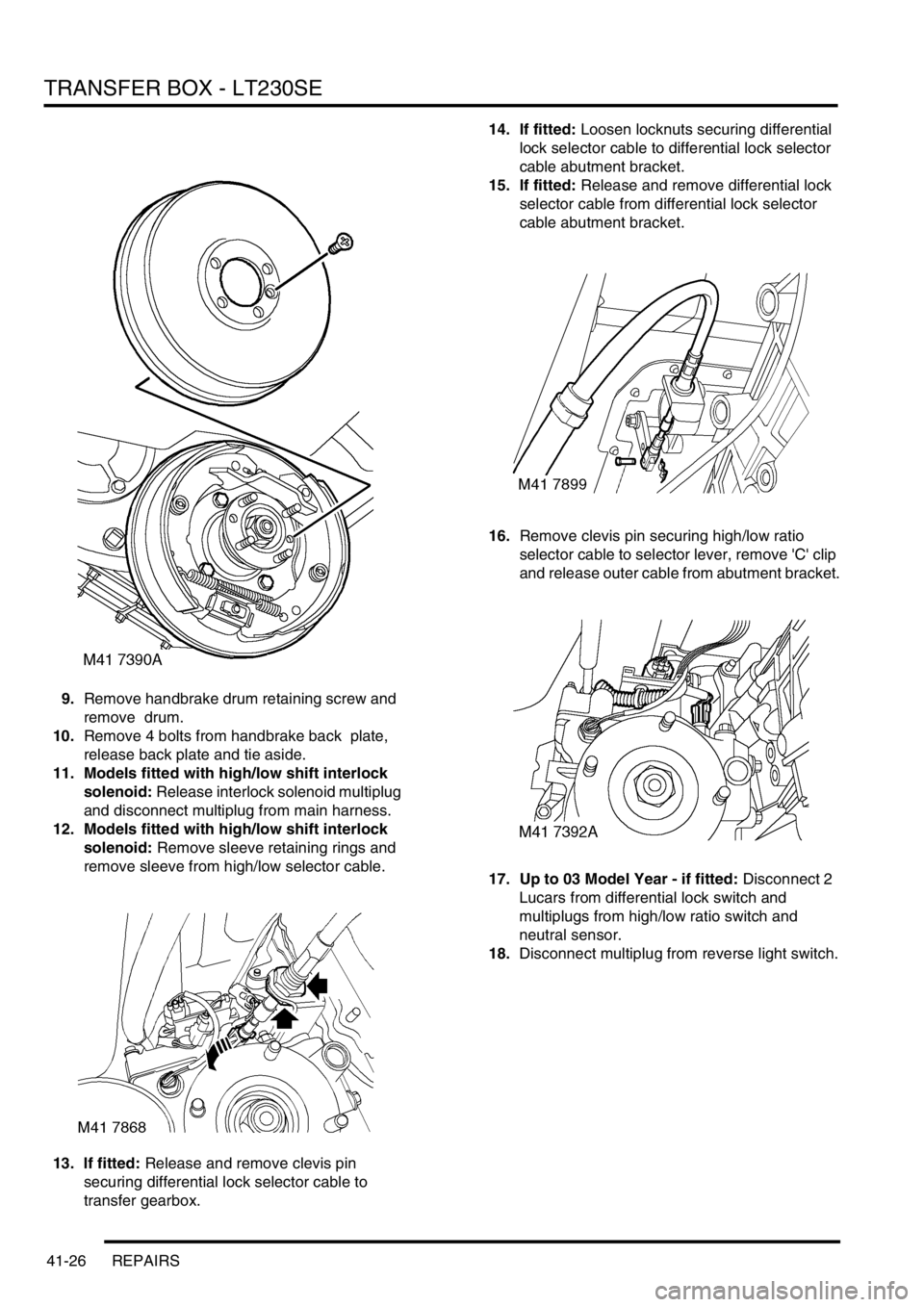
9.Remove handbrake drum retaining screw and
remove drum.
10.Remove 4 bolts from handbrake back plate,
release back plate and tie aside.
11. Models fitted with high/low shift interlock
solenoid: Release interlock solenoid multiplug
and disconnect multiplug from main harness.
12. Models fitted with high/low shift interlock
solenoid: Remove sleeve retaining rings and
remove sleeve from high/low selector cable.
13. If fitted: Release and remove clevis pin
securing differential lock selector cable to
transfer gearbox.14. If fitted: Loosen locknuts securing differential
lock selector cable to differential lock selector
cable abutment bracket.
15. If fitted: Release and remove differential lock
selector cable from differential lock selector
cable abutment bracket.
16.Remove clevis pin securing high/low ratio
selector cable to selector lever, remove 'C' clip
and release outer cable from abutment bracket.
17. Up to 03 Model Year - if fitted: Disconnect 2
Lucars from differential lock switch and
multiplugs from high/low ratio switch and
neutral sensor.
18.Disconnect multiplug from reverse light switch.
Page 553 of 1529

TRANSFER BOX - LT230SE
41-28 REPAIRS
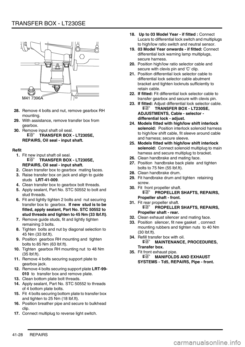
28.Remove 4 bolts and nut, remove gearbox RH
mounting.
29.With assistance, remove transfer box from
gearbox.
30.Remove input shaft oil seal.
+ TRANSFER BOX - LT230SE,
REPAIRS, Oil seal - input shaft.
Refit
1.Fit new input shaft oil seal.
+ TRANSFER BOX - LT230SE,
REPAIRS, Oil seal - input shaft.
2.Clean transfer box to gearbox mating faces.
3.Raise transfer box on jack and align to guide
studs LRT-41-009.
4.Clean transfer box to gearbox bolt threads.
5.Apply sealant, Part No. STC 50552 to bolt and
stud threads.
6.Fit and lightly tighten 2 bolts and nut securing
transfer box to gearbox. If new stud is to be
fitted, apply sealant, Part No. STC 50552 to
stud threads and tighten to 45 Nm (33 lbf.ft).
7.Remove guide studs, fit and lightly tighten
remaining 3 bolts.
8.Tighten bolts and nut by diagonal selection to
45 Nm (33 lbf.ft).
9.Position gearbox RH mounting and tighten
bolts to 85 Nm (63 lbf.ft).
10.Tighten gearbox RH mounting nut to 48 Nm
(35 lbf.ft).
11.Remove 4 bolts securing support plate to
gearbox jack.
12.Remove 4 bolts securing support plate LRT-99-
010 to transfer box and remove plate.
13.Clean bottom plate bolt threads.
14.Apply sealant, Part No. STC 50552 to threads
of 4 bottom plate bolts.
15.Fit 4 bolts securing bottom plate to transfer box
and tighten to 25 Nm (18 lbf.ft).
16.Position breather pipe and secure to bulkhead
clip.
17.Connect multiplug to reverse light switch. 18. Up to 03 Model Year - if fitted : Connect
Lucars to differential lock switch and multiplugs
to high/low ratio switch and neutral sensor.
19. 03 Model Year onwards - if fitted: Connect
differential lock warning lamp multiplugs,
secure harness.
20.Position high/low ratio selector cable and
secure with clevis pin and 'C' clip.
21.Position differential lock selector cable to
differential lock selector cable abutment
bracket and tighten locknuts sufficiently to
retain cable.
22. If fitted: Fit differential lock selector cable to
transfer gearbox and secure with clevis pin.
23. If fitted: Adjust differential lock selector cable.
+ TRANSFER BOX - LT230SE,
ADJUSTMENTS, Cable - selector -
differential lock - adjust.
24. Models fitted with high/low shift interlock
solenoid: Position interlock solenoid harness
to high/low shift cable, fit sleeve around cable
and harness; secure sleeve.
25. Models fitted with high/low shift interlock
solenoid: Connect solenoid multiplug to main
harness and secure multiplug to bracket.
26.Clean handbrake and mating face.
27.Position handbrake back plate and tighten
bolts to 75 Nm (55 lbf.ft).
28.Clean handbrake drum.
29.Fit handbrake drum and tighten retaining
screw.
30.Fit front propeller shaft.
+ PROPELLER SHAFTS, REPAIRS,
Propeller shaft - front.
31.Fit rear propeller shaft.
+ PROPELLER SHAFTS, REPAIRS,
Propeller shaft - rear.
32.Clean exhaust silencer and mating face.
33.Position silencer, fit new gasket , connect
mounting rubbers and tighten nuts to 40 Nm
(30 lbf.ft).
34.Refill transfer box with oil.
+ MAINTENANCE, PROCEDURES,
Transfer box.
35.Fit front exhaust pipe.
+ MANIFOLDS AND EXHAUST
SYSTEMS - Td5, REPAIRS, Pipe - front.
Page 557 of 1529

TRANSFER BOX - LT230SE
41-32 REPAIRS
Refit
1.Fit new input shaft oil seal.
+ TRANSFER BOX - LT230SE,
REPAIRS, Oil seal - input shaft.
2.Clean transfer box to gearbox mating faces.
3.Raise transfer box on jack and align to guide
studs LRT-41-009.
4.Clean transfer box to gearbox bolt threads.
5.Apply sealant, Part No. STC 50552 to bolt and
stud threads.
6.Fit and lightly tighten 2 bolts and nut securing
transfer box to gearbox. If new stud is to be
fitted, apply sealant, Part No. STC 50552 to
stud threads and tighten to 45 Nm (33 lbf.ft).
7.Remove guide studs, fit and lightly tighten 3
bolts.
8.Tighten bolts and nut by diagonal selection to
45 Nm (33 lbf.ft.
9.Position gearbox RH mounting and tighten
bolts to 85 Nm (63 lbf.ft).
10.Tighten gearbox RH mounting nut to 48 Nm
(35 lbf.ft).
11.Fit nut to LH mounting and tighten to 48 Nm (35
lbf.ft).
12.Remove 4 bolts securing support plate to
gearbox jack.
13.Remove 4 bolts securing support plate LRT-99-
010 to transfer box and remove plate.
14.Clean threads of bottom plate bolts.
15.Apply sealant, Part No. STC 50552 to threads
of 4 bottom plate bolts.
16.Fit 4 bolts securing bottom plate and tighten to
25 Nm (18 lbf.ft).
17.Using new washers position breather pipe and
tighten banjo bolt.
18.Connect multiplug to transfer box neutral switch
and secure harness.
19. Up to 03 Model Year - if fitted : Connect
Lucars to differential lock switch and multiplugs
to high/low ratio switch and neutral sensor.
20. 03 Model Year onwards - if fitted: Connect
differential lock warning lamp multiplugs,
secure harness.
21.Connect multiplug to reverse lamp switch.
22. If fitted: Connect Lucars to oil temperature
switch.
23.Position high/low ratio selector cable and
secure with 'C' clip and clevis pin.
24. If fitted: Position differential lock selector cable
to differential lock selector cable abutment
bracket and tighten locknuts sufficiently to
retain cable.
25. If fitted: Fit differential lock selector cable to
transfer gearbox and secure with clevis pin.
26. If fitted: Adjust differential lock selector cable.
+ TRANSFER BOX - LT230SE,
ADJUSTMENTS, Cable - selector -
differential lock - adjust.27. Models fitted with high/low shift interlock
solenoid: Position interlock solenoid harness
to high/low shift cable, fit sleeve around cable
and harness; secure sleeve.
28. Models fitted with high/low shift interlock
solenoid: Connect solenoid multiplug to main
harness and secure multiplug to bracket.
29.Secure cable to fuel pipes with new cable ties.
30.Clean handbrake back plate and mating face.
31.Position handbrake back plate, fit bolts and
tighten to 75 Nm (55 lbf.ft).
32.Clean handbrake drum.
33.Fit handbrake drum and tighten retaining
screw.
34.Fit front propeller shaft.
+ PROPELLER SHAFTS, REPAIRS,
Propeller shaft - front.
35.Fit rear propeller shaft.
+ PROPELLER SHAFTS, REPAIRS,
Propeller shaft - rear.
36.Clean exhaust silencer and tail pipe mating
faces.
37.Position silencer and secure on mountings,
using a new gasket align to tail pipe, fit nuts
and tighten to 25 Nm (18 lbf.ft).
38.Position rear cross member, fit bolts and
tighten to 26 Nm (19 lbf.ft).
39.Refill transfer box with oil.
+ MAINTENANCE, PROCEDURES,
Transfer box.
40.Fit front exhaust pipe.
+ MANIFOLDS AND EXHAUST
SYSTEMS - V8, REPAIRS, Front pipe.
Page 607 of 1529

AUTOMATIC GEARBOX - ZF4HP22 - 24
44-10 DESCRIPTION AND OPERATION
The lock-up and brake clutches are operated by pressurised transmission fluid from the valve block in the sump. A
manual valve and four solenoid valves, also known as Motorised Valves (MV), control the supply of pressurised
transmission fluid from the valve block:
lThe manual valve controls the supply in P, R, N and D.
lSolenoid valves MV 1 and MV 2 control the supplies that operate the brake clutches for shift control.
lSolenoid valve MV 3 controls the supply that operates the lock-up clutch.
lSolenoid valve MV 4 modulates the pressure of the supplies to the brake clutches, to control shift quality.
Operation of the manual valve is controlled by the selector lever assembly. In the gearbox, a selector shaft engages
with the manual valve. The selector shaft is connected to the selector lever assembly via the selector cable and a
selector lever on the left side of the gearbox. The selector shaft also operates a mechanism that locks the output shaft
when P is selected.
Operation of the solenoid valves is controlled by the EAT ECU.
An output shaft speed sensor in the gearbox housing outputs a signal to the EAT ECU. The EAT ECU compares
output shaft speed with engine speed to determine the engaged gear, and output shaft speed with vehicle speed to
confirm the range selected on the transfer box.
A bayonet lock electrical connector in the gearbox casing, to the rear of the selector lever, connects the solenoid
valves and the output shaft speed sensor to the vehicle wiring.
A pressed steel sump encloses the valve block and collects transmission fluid draining from the gearbox housing. A
suction pipe and filter on the underside of the valve block connect to the inlet side of the fluid pump. A magnet is
installed in the sump to collect any magnetic particles that may be present. A level plug and a drain plug are installed
in the sump for servicing.
Rear extension housing
The rear extension housing provides the interface between the gearbox housing and the transfer box. A splined
extension shaft, secured to the gearbox output shaft by a bolt, transmits the drive from the gearbox to the transfer
box. A seal in the rear of the housing prevents leakage past the extension shaft. A breather pipe, attached to the left
side of the rear extension housing, ventilates the interior of the gearbox and rear extension housings to atmosphere.
The open end of the breather pipe is located in the engine compartment at the right front corner of the engine sump
on gearboxes fitted to early vehicles and is clipped to the top of the gearbox on later vehicles.
Gearbox power flows
The following Figures show the power flow through the gearbox for each forward gear when D is selected, and for
reverse. The key to the Item numbers on the Figures, and in parenthesis in the accompanying text, can be found on
the 'Sectioned view of gearbox' Figure, above.
1st Gear (D selected)
Clutches (4) and (11) are engaged. The front planet gear carrier of gear set (9) locks against the gearbox housing
through freewheel (15) when the engine powers the vehicle, and freewheels when the vehicle is coasting. Gear set
(10) rotates as a solid unit with the front planet gear carrier. In 1st gear hold brake clutch (8) is applied to provide
overrun braking.
Page 625 of 1529

AUTOMATIC GEARBOX - ZF4HP22 - 24
44-28 REPAIRS
15.Remove handbrake drum retaining screw and
remove brake drum.
16.Remove 4 bolts from handbrake back plate,
release back plate and tie aside.
17. Models fitted with high/low shift interlock
solenoid: Release interlock solenoid multiplug
and disconnect multiplug from main harness.
18. Models fitted with high/low shift interlock
solenoid: Remove sleeve retaining rings and
remove sleeve from high/low selector cable.
19. If fitted Remove and discard clevis pin
securing differential lock selector cable to
transfer gearbox.20. If fitted Loosen locknuts securing differential
lock selector cable to differential lock selector
cable abutment bracket.
21. If fitted Release and remove differential lock
selector cable from differential lock selector
cable abutment bracket.
22.Remove clevis pin securing high/low ratio
selector cable to selector lever, remove 'C' clip
and remove outer cable from abutment
bracket.
23. Up to 03 Model Year - If fitted: Disconnect
from differential lock warning lamp switch and
multiplugs from high/low ratio switch and
neutral sensor.
Page 628 of 1529

AUTOMATIC GEARBOX - ZF4HP22 - 24
REPAIRS 44-31
40.Fit suitable strap to retain torque converter.
Refit
1.Clean gearbox to engine mating faces.
2.Remove torque converter retaining strap.
3.With assistance position gearbox to engine.
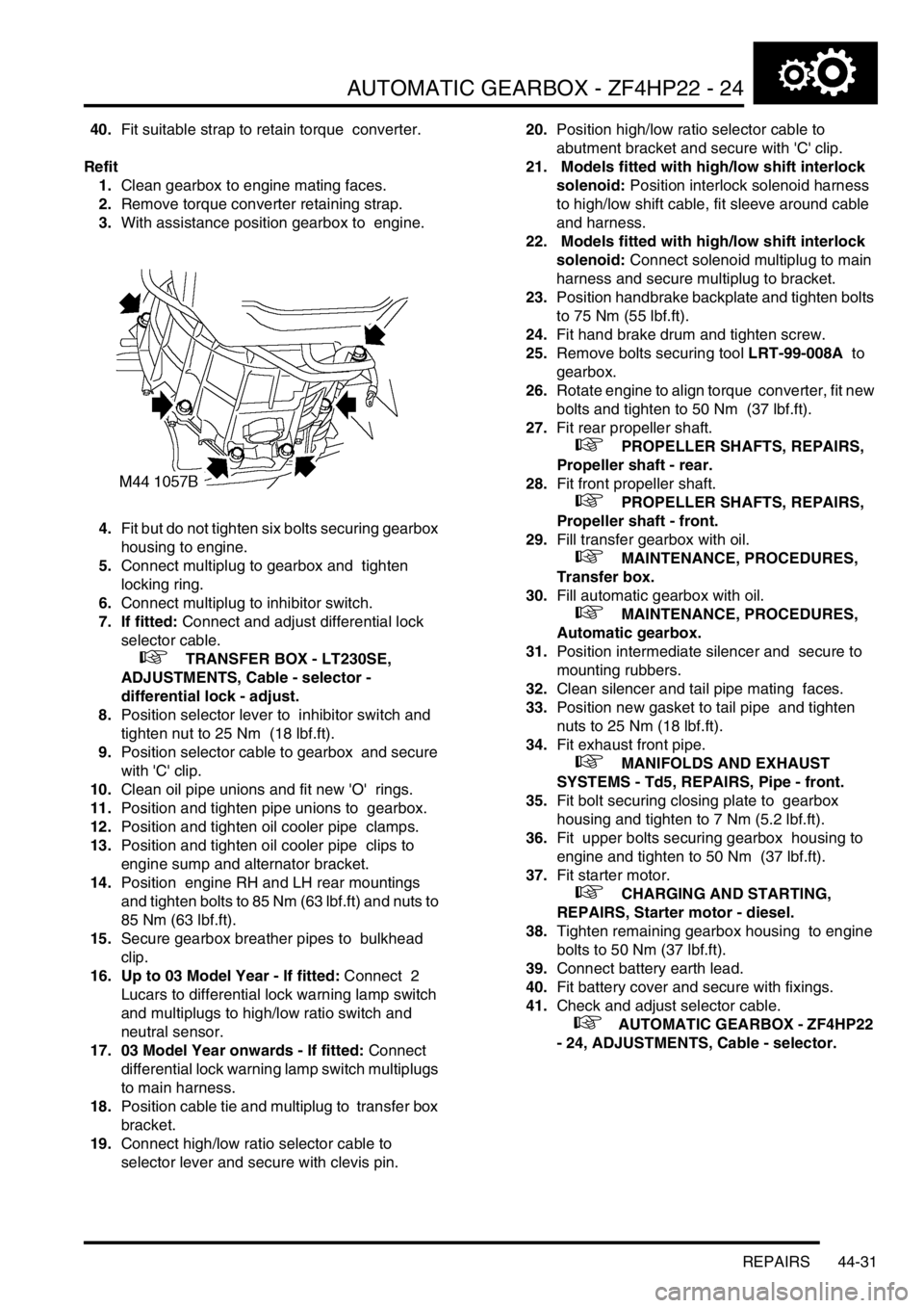
4.Fit but do not tighten six bolts securing gearbox
housing to engine.
5.Connect multiplug to gearbox and tighten
locking ring.
6.Connect multiplug to inhibitor switch.
7. If fitted: Connect and adjust differential lock
selector cable.
+ TRANSFER BOX - LT230SE,
ADJUSTMENTS, Cable - selector -
differential lock - adjust.
8.Position selector lever to inhibitor switch and
tighten nut to 25 Nm (18 lbf.ft).
9.Position selector cable to gearbox and secure
with 'C' clip.
10.Clean oil pipe unions and fit new 'O' rings.
11.Position and tighten pipe unions to gearbox.
12.Position and tighten oil cooler pipe clamps.
13.Position and tighten oil cooler pipe clips to
engine sump and alternator bracket.
14.Position engine RH and LH rear mountings
and tighten bolts to 85 Nm (63 lbf.ft) and nuts to
85 Nm (63 lbf.ft).
15.Secure gearbox breather pipes to bulkhead
clip.
16. Up to 03 Model Year - If fitted: Connect 2
Lucars to differential lock warning lamp switch
and multiplugs to high/low ratio switch and
neutral sensor.
17. 03 Model Year onwards - If fitted: Connect
differential lock warning lamp switch multiplugs
to main harness.
18.Position cable tie and multiplug to transfer box
bracket.
19.Connect high/low ratio selector cable to
selector lever and secure with clevis pin. 20.Position high/low ratio selector cable to
abutment bracket and secure with 'C' clip.
21. Models fitted with high/low shift interlock
solenoid: Position interlock solenoid harness
to high/low shift cable, fit sleeve around cable
and harness.
22. Models fitted with high/low shift interlock
solenoid: Connect solenoid multiplug to main
harness and secure multiplug to bracket.
23.Position handbrake backplate and tighten bolts
to 75 Nm (55 lbf.ft).
24.Fit hand brake drum and tighten screw.
25.Remove bolts securing tool LRT-99-008A to
gearbox.
26.Rotate engine to align torque converter, fit new
bolts and tighten to 50 Nm (37 lbf.ft).
27.Fit rear propeller shaft.
+ PROPELLER SHAFTS, REPAIRS,
Propeller shaft - rear.
28.Fit front propeller shaft.
+ PROPELLER SHAFTS, REPAIRS,
Propeller shaft - front.
29.Fill transfer gearbox with oil.
+ MAINTENANCE, PROCEDURES,
Transfer box.
30.Fill automatic gearbox with oil.
+ MAINTENANCE, PROCEDURES,
Automatic gearbox.
31.Position intermediate silencer and secure to
mounting rubbers.
32.Clean silencer and tail pipe mating faces.
33.Position new gasket to tail pipe and tighten
nuts to 25 Nm (18 lbf.ft).
34.Fit exhaust front pipe.
+ MANIFOLDS AND EXHAUST
SYSTEMS - Td5, REPAIRS, Pipe - front.
35.Fit bolt securing closing plate to gearbox
housing and tighten to 7 Nm (5.2 lbf.ft).
36.Fit upper bolts securing gearbox housing to
engine and tighten to 50 Nm (37 lbf.ft).
37.Fit starter motor.
+ CHARGING AND STARTING,
REPAIRS, Starter motor - diesel.
38.Tighten remaining gearbox housing to engine
bolts to 50 Nm (37 lbf.ft).
39.Connect battery earth lead.
40.Fit battery cover and secure with fixings.
41.Check and adjust selector cable.
+ AUTOMATIC GEARBOX - ZF4HP22
- 24, ADJUSTMENTS, Cable - selector.
Page 668 of 1529

REAR AXLE
DESCRIPTION AND OPERATION 51-3
Wheel hub
Section through wheel hub
1'O' ring
2Hub bearing
3Hub flange
4Wheel stud5Stake nut
6ABS sensor ring
7Drive shaft
8Axle casing
Each wheel hub consists of a hub flange pressed into a hub bearing.
The hub flange is splined to accept the outboard end of the drive shaft, which is secured to the hub flange with a stake
nut. Five studs are installed in the hub flange for the wheel nuts, and a threaded hole is provided for the brake disc
securing screw.
The outer race of the hub bearing is bolted to the end of the axle casing. An 'O' ring seals the joint between the outer
race and the axle casing to prevent leakage of differential lubricating oil. The hub bearing is a sealed unit which
contains twin opposed roller bearings, pre-packed with grease during manufacture. A toothed ABS sensor ring is
integrated into the inner race of the hub bearing. An opening in the outer race of the hub bearing accommodates the
ABS sensor.
Drive shaft
Each drive shaft consists of a solid rod, splined at both ends.
Page 670 of 1529

REAR AXLE
REPAIRS 51-5
REPAIRS
Differential - assembly
$% 51.15.01
Remove
1.Raise rear of vehicle.
WARNING: Do not work on or under a
vehicle supported only by a jack. Always
support the vehicle on safety stands.
2.Drain oil from differential.
+ MAINTENANCE, PROCEDURES,
Front and rear axle.
3.If same components are to be refitted,
reference mark propeller shaft and mating
components.
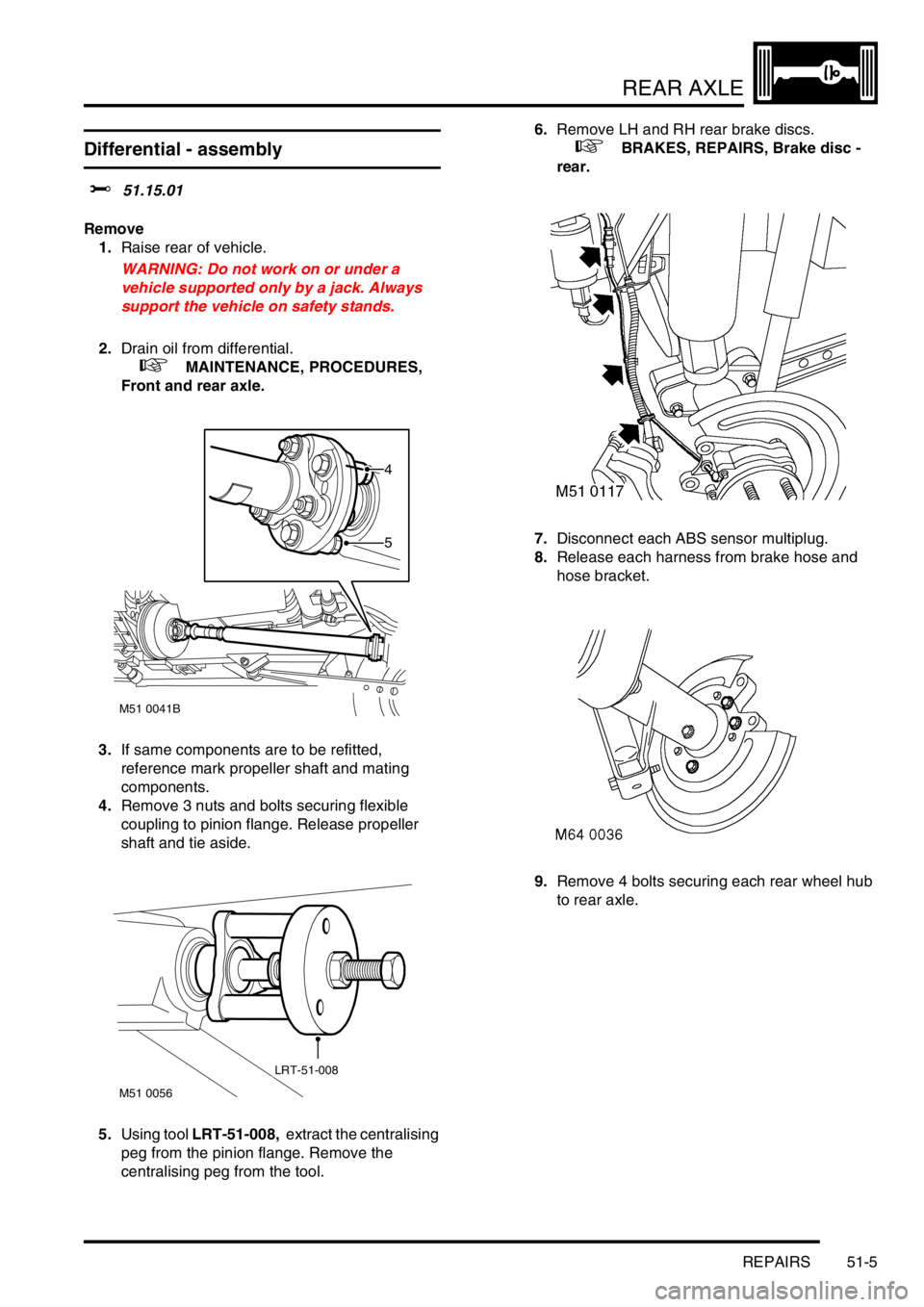
4.Remove 3 nuts and bolts securing flexible
coupling to pinion flange. Release propeller
shaft and tie aside.
5.Using tool LRT-51-008, extract the centralising
peg from the pinion flange. Remove the
centralising peg from the tool.6.Remove LH and RH rear brake discs.
+ BRAKES, REPAIRS, Brake disc -
rear.
7.Disconnect each ABS sensor multiplug.
8.Release each harness from brake hose and
hose bracket.
9.Remove 4 bolts securing each rear wheel hub
to rear axle.
M51 0041B
5
4
M51 0056
LRT-51-008