navigation LAND ROVER DISCOVERY 1999 User Guide
[x] Cancel search | Manufacturer: LAND ROVER, Model Year: 1999, Model line: DISCOVERY, Model: LAND ROVER DISCOVERY 1999Pages: 1529, PDF Size: 34.8 MB
Page 1462 of 1529

NAVIGATION SYSTEM
DESCRIPTION AND OPERATION 87-9
A = Distance, miles (km); B = Start/Finish point
Reset
If the navigation system malfunctions, a system reset can be triggered by simultaneously pressing the TP button and
multifunction button 1 or 3. The navigation CD will need to be installed after the system reset.
Steering Wheel Switches
The steering wheel switches provide remote control operation for some of the navigation computer functions. The
switches can be used to select between the radio/CD/navigation modes, to adjust the volume (in all modes) and to
select search/preset up/down for radio and CD operation.
Remote Control Interface Unit
The remote control interface unit converts the analogue signals from the steering wheel switches into digital signals
for use by the navigation computer. The remote control interface unit is installed in a bracket immediately below the
navigation computer.
The radio remote switches form a resistance ladder between two wires with the resistance across wires dependent
on which switch is pressed. The remote control interface unit monitors the two wires and converts their input into
Instrument (I) bus protocol messages, which it outputs on a dedicated serial link to the navigation computer.
Page 1464 of 1529

NAVIGATION SYSTEM
DESCRIPTION AND OPERATION 87-11
Deze pagina werd opzettelijk niet gebruikt
Cette page est intentionnellement vierge
Questa pagina è stata lasciata in bianco di proposito Diese Seite ist leer
Esta página foi deixada intencionalmente em branco
Esta página fue dejada en blanco intencionalmente This page is intentionally left blank
DESCRIPTION AND OPERAT ION
Page 1465 of 1529

NAVIGATION SYSTEM
87-12 DESCRIPTION AND OPERATION
CARiN III Navigation and Trafficmaster
System Component Location
Page 1466 of 1529

NAVIGATION SYSTEM
DESCRIPTION AND OPERATION 87-13
1GPS antenna
2Display unit
3Switch pack
4Trafficmaster antenna
5Navigation speaker
6Trafficmaster monitor unit
7Navigation computer
Page 1467 of 1529

NAVIGATION SYSTEM
87-14 DESCRIPTION AND OPERATION
Description
General
Where fitted, the CARiN III and Trafficmaster system combines a satellite navigation system (CARiN III) with a real-
time traffic information system (Trafficmaster).
The satellite navigation system provides computer generated audible and visual route guidance information to enable
the driver to reach a desired destination. The system allows the driver to choose between road navigation and off-
road navigation, and to incorporate waypoints. Road navigation also allows the driver to choose between using minor
or major roads and the quickest or shortest route. Directions to hospitals, museums, monuments, hotels etc. are also
available. The computer uses map information stored on a CD-ROM to determine the best route for the journey and
provide the driver with details of directions and approaching junctions. The current position of the vehicle is
determined using a combination of vehicle sensor inputs and the Global Positioning System (GPS).
The Trafficmaster system displays live traffic flow information on the road navigation map screens. Traffic speed is
indicated on the maps by colour coded roads and arrows. The traffic flow information is relayed from a network of
sensors covering motorways and trunk roads. Data from the sensors is updated on a three minute cycle, 24 hours a
day, 365 days a year.
The navigation system consists of the following components:
lNavigation computer
lGPS antenna
lDisplay unit
lSwitch pack
lNavigation speaker
lTrafficmaster monitor ECU
lTrafficmaster antenna
Navigation Computer
The navigation computer is located in a bracket under the RH front seat, immediately behind the CD autochanger.
The navigation computer contains all the hardware and software required for control of the navigation system,
including the GPS receiver and a solid state piezo gyro. Using the gyro, and inputs from the GPS antenna and the
vehicle K bus, the navigation computer determines the vehicle’s current position, direction and speed.
The navigation computer also houses a CD-ROM drive. The drive is used to read map data from country specific CD’s
and also to load software into the computer. A button, adjacent to the CD slot, is provided to eject the CD from the
unit. If the ignition is on, one press of the button will eject the CD. If the ignition is off, two presses are required, one
to wake up the system and the second to eject the CD. Access to the CD-ROM drive is from the rear of the RH front
seat.
Page 1468 of 1529

NAVIGATION SYSTEM
DESCRIPTION AND OPERATION 87-15
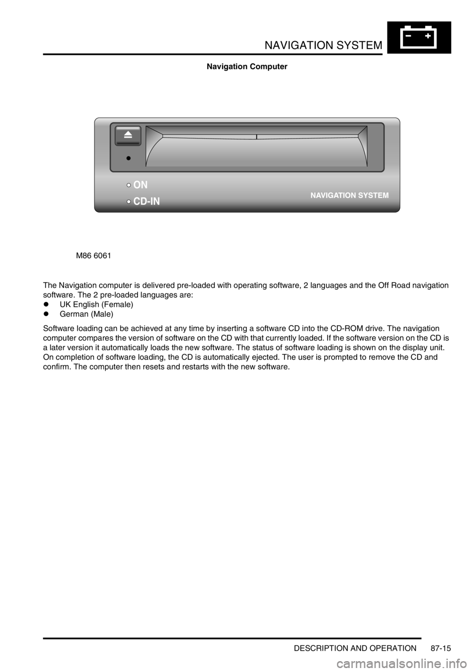
Navigation Computer
The Navigation computer is delivered pre-loaded with operating software, 2 languages and the Off Road navigation
software. The 2 pre-loaded languages are:
lUK English (Female)
lGerman (Male)
Software loading can be achieved at any time by inserting a software CD into the CD-ROM drive. The navigation
computer compares the version of software on the CD with that currently loaded. If the software version on the CD is
a later version it automatically loads the new software. The status of software loading is shown on the display unit.
On completion of software loading, the CD is automatically ejected. The user is prompted to remove the CD and
confirm. The computer then resets and restarts with the new software.
M86 6061
ON
CD-IN
Page 1469 of 1529

NAVIGATION SYSTEM
87-16 DESCRIPTION AND OPERATION
Piezo Gyro Sensor
1Driver elements
2Retaining element
3Amplifier
4Phase detector5Frequency filter
6Navigation computer
7Driver stage
The piezo gyro measures the motion of the vehicle around its vertical axis using the Coriolis force. The Coriolis force
is a force which accelerates a body moving away from the rotational axis against the direction of rotation of that axis.
In operation, a mass inside the sensor is excited to a point where it begins to vibrate, similar to a tuning fork. The
vibrations travel perpendicular to the rotational axis and cause continuous potential charge of the mass in relation to
the rotational axis. The forces are measured and converted into a yaw rate to calculate direction.
The sensor is supplied with a current from a driver stage. The current induces vibrations in the driver elements and
retaining elements. As the vehicle turns a corner, the rotational motion is detected by the retaining elements due to
the Coriolis force, and a small electrical voltage is produced.
The voltage is passed to an amplifier and the amplified signal is then passed to a phase detector. The phase detector
establishes the direction of rotation and passes a signal to a frequency filter. Because the gyro sensor is subject to
vibrations produced by means other than cornering, the frequency filter analyses the signals and removes signals not
produced by cornering forces. The filtered signal is passed from the frequency filter to the navigation computer, which
uses it to calculate the direction of travel.
Page 1470 of 1529

NAVIGATION SYSTEM
DESCRIPTION AND OPERATION 87-17
GPS Antenna
The GPS antenna is installed on the rear of the roof, on the vehicle centreline. A diplexer unit on the underside of the
GPS antenna amplifies the radio signals received from the GPS satellites and transmits them through a co-axial cable
to the navigation computer for processing.
Display Unit
The display unit is integrated into the front stowage pocket, above the rear view mirror. The display unit is a colour
Liquid Crystal Display (LCD) that shows the programming menus, route guidance and traffic information. The display
illumination level automatically dims for night time viewing when the exterior lights are switched on.
Page 1471 of 1529

NAVIGATION SYSTEM
87-18 DESCRIPTION AND OPERATION
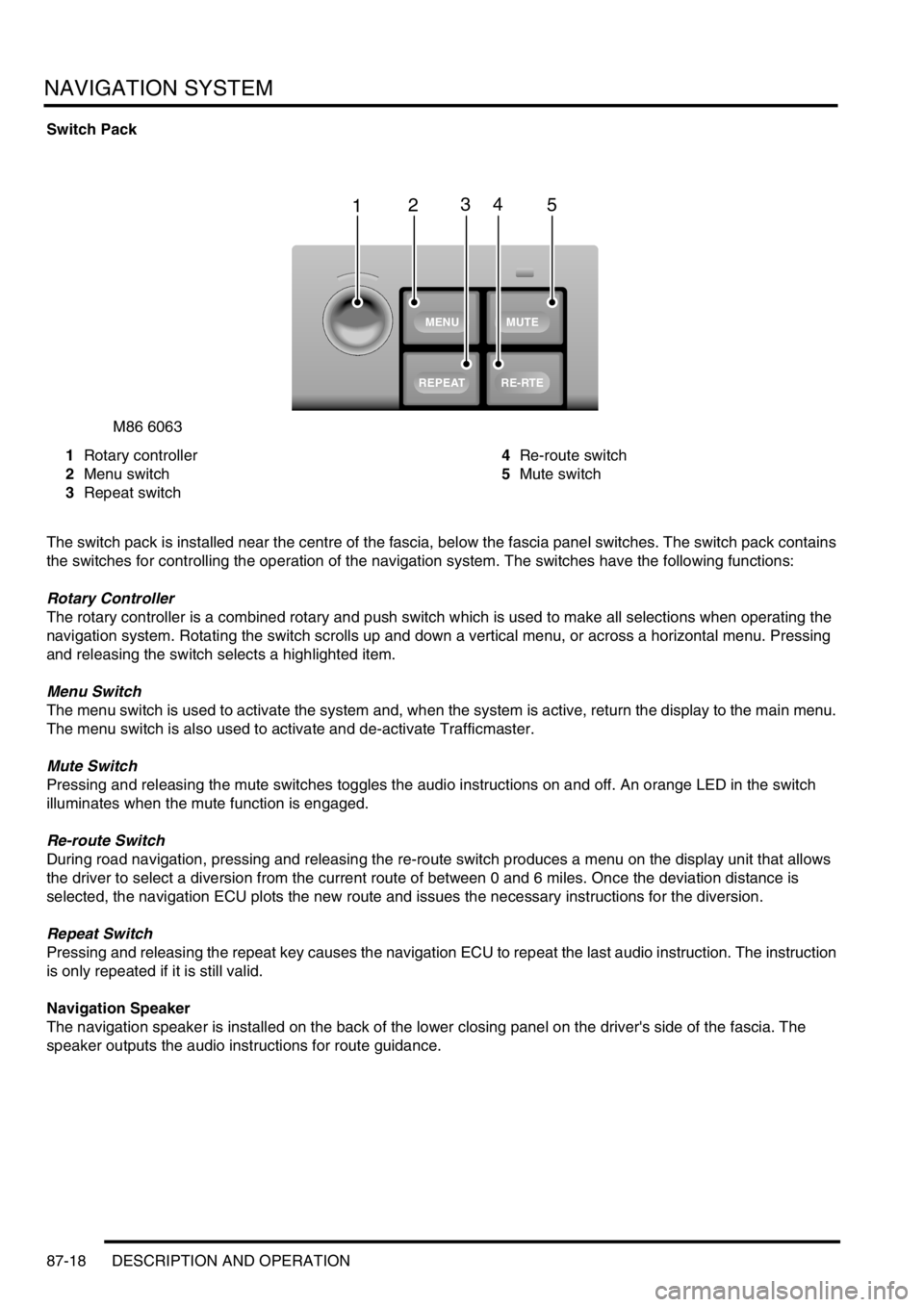
Switch Pack
1Rotary controller
2Menu switch
3Repeat switch4Re-route switch
5Mute switch
The switch pack is installed near the centre of the fascia, below the fascia panel switches. The switch pack contains
the switches for controlling the operation of the navigation system. The switches have the following functions:
Rotary Controller
The rotary controller is a combined rotary and push switch which is used to make all selections when operating the
navigation system. Rotating the switch scrolls up and down a vertical menu, or across a horizontal menu. Pressing
and releasing the switch selects a highlighted item.
Menu Switch
The menu switch is used to activate the system and, when the system is active, return the display to the main menu.
The menu switch is also used to activate and de-activate Trafficmaster.
Mute Switch
Pressing and releasing the mute switches toggles the audio instructions on and off. An orange LED in the switch
illuminates when the mute function is engaged.
Re-route Switch
During road navigation, pressing and releasing the re-route switch produces a menu on the display unit that allows
the driver to select a diversion from the current route of between 0 and 6 miles. Once the deviation distance is
selected, the navigation ECU plots the new route and issues the necessary instructions for the diversion.
Repeat Switch
Pressing and releasing the repeat key causes the navigation ECU to repeat the last audio instruction. The instruction
is only repeated if it is still valid.
Navigation Speaker
The navigation speaker is installed on the back of the lower closing panel on the driver's side of the fascia. The
speaker outputs the audio instructions for route guidance.
M86 6063
1
MUTE
RE-RTE
REPEAT
MENU
2345
Page 1472 of 1529

NAVIGATION SYSTEM
DESCRIPTION AND OPERATION 87-19
Trafficmaster Monitor ECU
The Trafficmaster monitor ECU is installed underneath the CD autochanger, below the RH front seat. The
Trafficmaster monitor ECU processes the traffic flow data from the Trafficmaster antenna and combines it with data
from the navigation computer to display on the display unit.
Trafficmaster Antenna
The Trafficmaster antenna is installed in the fascia, on the rear of the instrument pack. The antenna receives radio
signals containing the data relayed from the traffic flow sensors, and transmits the information on a hardwired
connection to the Trafficmaster monitor ECU.