tow LAND ROVER DISCOVERY 1999 User Guide
[x] Cancel search | Manufacturer: LAND ROVER, Model Year: 1999, Model line: DISCOVERY, Model: LAND ROVER DISCOVERY 1999Pages: 1529, PDF Size: 34.8 MB
Page 115 of 1529

LIFTING AND TOWING
08-2
Before commencing work on underside of vehicle re-
check security of vehicle on stands.
WARNING: Always chock the wheels when
jacking. The hand brake acts on the the
transmission, not the rear wheels, and may be
ineffective when the wheels are off the ground.
Reverse procedure when removing vehicle from
stands.
Hydraulic ramps
Use only a 'drive on' type ramp which supports a
vehicle by it's own road wheels. If a 'wheel free'
condition is required, use a 'drive on' ramp
incorporating a 'wheel free' system that supports
under axle casings. Alternatively, place vehicle on a
firm, flat floor and support on axle stands.
TOWING
Towing
The vehicle has permanent four wheel drive. The
following towing instructions must be adhered
to:
Towing on 4 wheels with driver
Turn ignition key to position '1' to release steering
lock.
Select neutral in main gearbox and transfer gearbox.
Secure tow rope, chain or cable to towing eye.
Release the handbrake.
The brake servo and power assisted steering
system will not be functional without the engine
running. Greater pedal pressure will be required
to apply the brakes, the steering system will
require greater effort to turn the front road
wheels. The vehicle tow connection should be
used only in normal road conditions, 'snatch'
recovery should be avoided.
Suspended tow
To prevent vehicle damage, front or rear
propeller shaft MUST BE removed, dependent
upon which axle is being trailed.
Mark propeller shaft drive flanges at transfer box and
axles with identification lines to enable the propeller
shaft to be refitted in its original position.
Page 116 of 1529

LIFTING AND TOWING
08-3
Remove the propeller shaft fixings, remove the shaft
from the vehicle.
If the front axle is to be trailed turn ignition key to
position '1' to release steering lock.
The steering wheel and/or linkage must be
secured in a straight ahead position. DO NOT use
the steering lock mechanism for this purpose.
Towing eyes
The towing eyes at the front and rear of the vehicle
are designed for vehicle recovery purposes only and
must NOT be used to tow a trailer or caravan.
Front:A single towing eye, set behind a removable
panel in the front spoiler. DO NOT use the front
lashing rings for towing.Rear: A pair of towing eyes at the rear of the vehicle
can be used as lashing rings and for towing another
light vehicle.
Page 117 of 1529

LIFTING AND TOWING
08-4
TRANSPORTING
Transporting by trailer
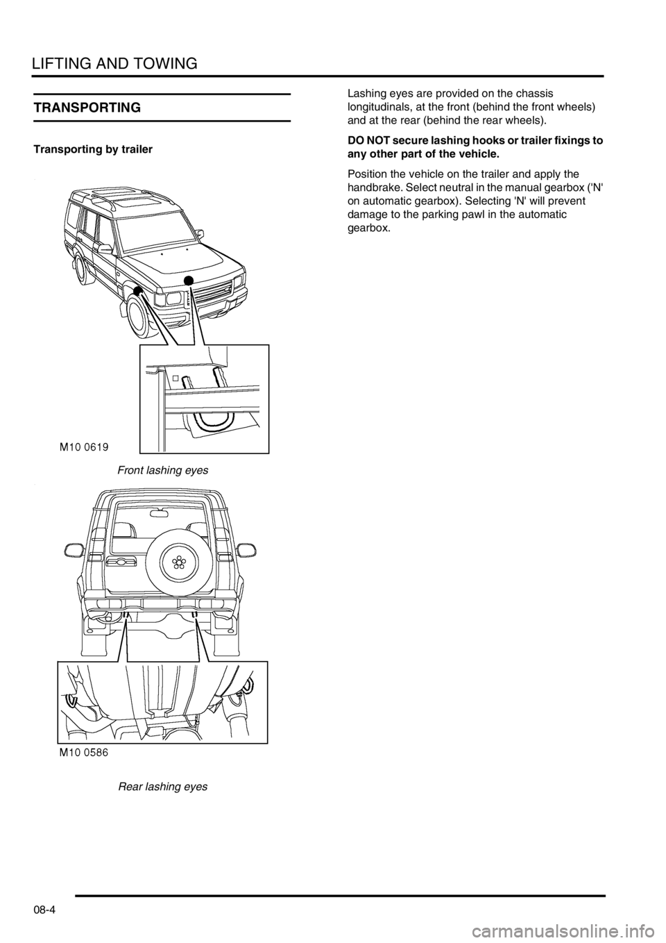
Front lashing eyes
Rear lashing eyesLashing eyes are provided on the chassis
longitudinals, at the front (behind the front wheels)
and at the rear (behind the rear wheels).
DO NOT secure lashing hooks or trailer fixings to
any other part of the vehicle.
Position the vehicle on the trailer and apply the
handbrake. Select neutral in the manual gearbox ('N'
on automatic gearbox). Selecting 'N' will prevent
damage to the parking pawl in the automatic
gearbox.
Page 152 of 1529

MAINTENANCE
PROCEDURES 10-29
Towing bracket
Check
1.Check security of towing bracket.
Page 187 of 1529

ENGINE - V8
12-2-32 REPAIRS
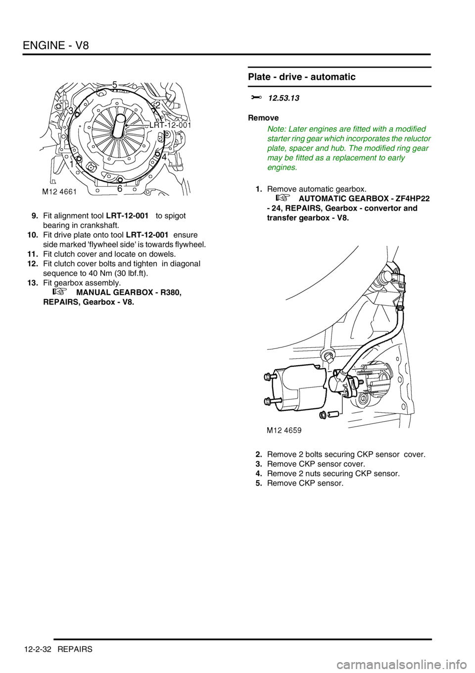
9.Fit alignment tool LRT-12-001 to spigot
bearing in crankshaft.
10.Fit drive plate onto tool LRT-12-001 ensure
side marked 'flywheel side' is towards flywheel.
11.Fit clutch cover and locate on dowels.
12.Fit clutch cover bolts and tighten in diagonal
sequence to 40 Nm (30 lbf.ft).
13.Fit gearbox assembly.
+ MANUAL GEARBOX - R380,
REPAIRS, Gearbox - V8.
Plate - drive - automatic
$% 12.53.13
Remove
Note: Later engines are fitted with a modified
starter ring gear which incorporates the reluctor
plate, spacer and hub. The modified ring gear
may be fitted as a replacement to early
engines.
1.Remove automatic gearbox.
+ AUTOMATIC GEARBOX - ZF4HP22
- 24, REPAIRS, Gearbox - convertor and
transfer gearbox - V8.
2.Remove 2 bolts securing CKP sensor cover.
3.Remove CKP sensor cover.
4.Remove 2 nuts securing CKP sensor.
5.Remove CKP sensor.
Page 195 of 1529

ENGINE - V8
12-2-40 REPAIRS
6.Remove 2 bolts securing radiator LH and RH
upper mounting brackets to body panel and
remove brackets.
7.Remove 4 screws securing air conditioning
condenser LH and RH upper mounting
brackets to condenser.
8.Remove condenser upper mounting brackets
with rubber mounts from radiator extension
brackets.
9.Remove 2 bolts securing LH and RH extension
brackets to radiator and remove brackets.
10.Position absorbent cloth under each oil cooler
hose connection to collect oil spillage. 11.Push against coupling release rings and
disconnect both hoses from oil cooler.
CAUTION: Always fit plugs to open
connections to prevent contamination.
12.Remove screw securing oil cooler to radiator.
13.Release cooler from its location on radiator.
14.Release radiator lower mountings from
location in chassis and carefully move radiator
towards engine sufficiently only to release
engine oil cooler from radiator.
15.Remove engine oil cooler.
Refit
1.Fit engine oil cooler to radiator, engage in
location and secure with screw.
2.Fit radiator to location in chassis.
3.Ensure connections are clean, then secure
hoses to oil cooler.
4.Fit extension brackets to radiator and secure
with bolts.
5.Fit brackets with rubber mounts to extension
brackets and secure to air conditioning
condenser with screws.
6.Fit radiator upper mounting brackets and
secure to body with bolts.
7.Fit LH horn and secure with nut.
8.Fit LH and RH air deflectors to front panel and
secure with scrivets.
9.Fit front grille.
+ EXTERIOR FITTINGS, REPAIRS,
Grille - front - up to 03MY..
10.Fit cooling fan cowl and secure with fixings.
11.Fit battery cover and secure with fixings.
12.Top up engine oil.
Page 220 of 1529

ENGINE - V8
OVERHAUL 12-2-65
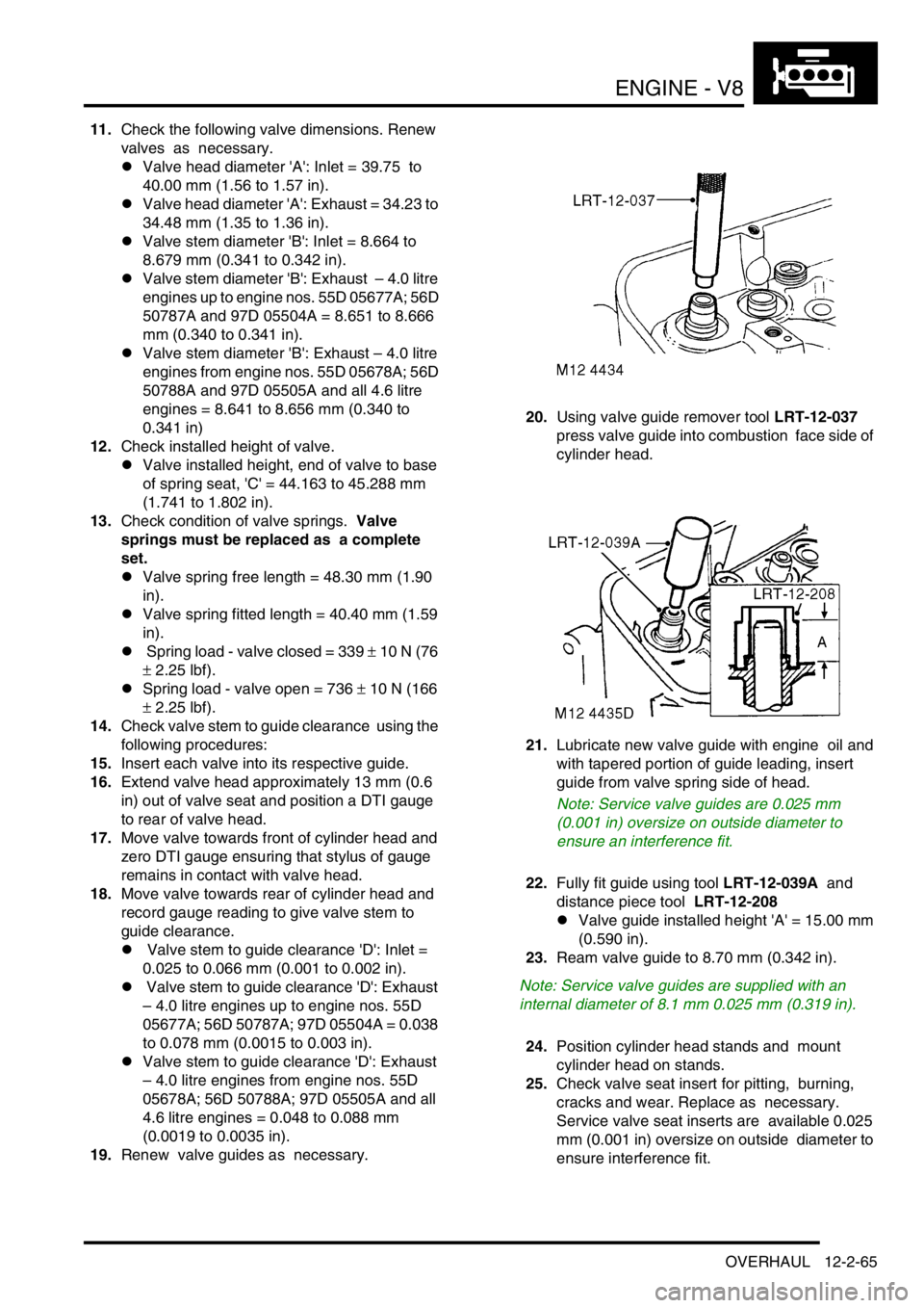
11.Check the following valve dimensions. Renew
valves as necessary.
lValve head diameter 'A': Inlet = 39.75 to
40.00 mm (1.56 to 1.57 in).
lValve head diameter 'A': Exhaust = 34.23 to
34.48 mm (1.35 to 1.36 in).
lValve stem diameter 'B': Inlet = 8.664 to
8.679 mm (0.341 to 0.342 in).
lValve stem diameter 'B': Exhaust – 4.0 litre
engines up to engine nos. 55D 05677A; 56D
50787A and 97D 05504A = 8.651 to 8.666
mm (0.340 to 0.341 in).
lValve stem diameter 'B': Exhaust – 4.0 litre
engines from engine nos. 55D 05678A; 56D
50788A and 97D 05505A and all 4.6 litre
engines = 8.641 to 8.656 mm (0.340 to
0.341 in)
12.Check installed height of valve.
lValve installed height, end of valve to base
of spring seat, 'C' = 44.163 to 45.288 mm
(1.741 to 1.802 in).
13.Check condition of valve springs. Valve
springs must be replaced as a complete
set.
lValve spring free length = 48.30 mm (1.90
in).
lValve spring fitted length = 40.40 mm (1.59
in).
l Spring load - valve closed = 339 ± 10 N (76
± 2.25 lbf).
lSpring load - valve open = 736 ± 10 N (166
± 2.25 lbf).
14.Check valve stem to guide clearance using the
following procedures:
15.Insert each valve into its respective guide.
16.Extend valve head approximately 13 mm (0.6
in) out of valve seat and position a DTI gauge
to rear of valve head.
17.Move valve towards front of cylinder head and
zero DTI gauge ensuring that stylus of gauge
remains in contact with valve head.
18.Move valve towards rear of cylinder head and
record gauge reading to give valve stem to
guide clearance.
l Valve stem to guide clearance 'D': Inlet =
0.025 to 0.066 mm (0.001 to 0.002 in).
l Valve stem to guide clearance 'D': Exhaust
– 4.0 litre engines up to engine nos. 55D
05677A; 56D 50787A; 97D 05504A = 0.038
to 0.078 mm (0.0015 to 0.003 in).
lValve stem to guide clearance 'D': Exhaust
– 4.0 litre engines from engine nos. 55D
05678A; 56D 50788A; 97D 05505A and all
4.6 litre engines = 0.048 to 0.088 mm
(0.0019 to 0.0035 in).
19.Renew valve guides as necessary. 20.Using valve guide remover tool LRT-12-037
press valve guide into combustion face side of
cylinder head.
21.Lubricate new valve guide with engine oil and
with tapered portion of guide leading, insert
guide from valve spring side of head.
Note: Service valve guides are 0.025 mm
(0.001 in) oversize on outside diameter to
ensure an interference fit.
22.Fully fit guide using tool LRT-12-039A and
distance piece tool LRT-12-208
lValve guide installed height 'A' = 15.00 mm
(0.590 in).
23.Ream valve guide to 8.70 mm (0.342 in).
Note: Service valve guides are supplied with an
internal diameter of 8.1 mm 0.025 mm (0.319 in).
24.Position cylinder head stands and mount
cylinder head on stands.
25.Check valve seat insert for pitting, burning,
cracks and wear. Replace as necessary.
Service valve seat inserts are available 0.025
mm (0.001 in) oversize on outside diameter to
ensure interference fit.
Page 224 of 1529

ENGINE - V8
OVERHAUL 12-2-69
9.Check overall dimensions of gudgeon pin.
Gudgeon pins are only supplied as an
assembly with replacement pistons.
lGudgeon pin length = 60.00 to 60.50 mm
(2.362 to 2.382 in).
lGudgeon pin diameter = 23.995 to 24.00
mm (0.9446 to 0.9448 in)
10.Measure cylinder bore wear and ovality in two
axis 40 to 50 mm (1.6 to 2 in) from top of bore.
The temperature of piston and cylinder
block must be the same to ensure accurate
measurement. Do not attempt to de-glaze
cylinder bores.
lGrade 'A' pistons: Cylinder bore = 94.00 to
94.015 mm (3.7007 to 3.7013 in).
lGrade 'B' pistons: Cylinder bore = 94.016 to
94.030 mm (3.7014 to 3.7019 in).
lMaximum ovality = 0.013 mm (0.0005 in).
11.Check alignment of connecting rods. Reassembly
1.Pistons have a 5 mm (0.2 in) offset gudgeon pin
which can be identified by an arrow mark on
the piston crown. This arrow must always point
towards the front of the engine.
2.Assemble pistons to connecting rods with
arrow on piston pointing towards domed
shaped boss on connecting rod for RH bank of
cylinders and arrow pointing away from domed
shaped boss for LH bank of cylinders.
3.Clamp hexagon body of tool LRT-12-013 in
vice.
4.Screw large nut back until flush with end of
centre screw.
5.Locate remover/replacer adapter LRT-12-126/
2 with its long spigot inside bore of hexagon
body.
6.Fit parallel sleeve, part of tool LRT-12-013,
ensuring that grooved end is towards open end
of tool LRT-12-013. Position sleeve up to
shoulder of centre screw.
7.Lubricate gudgeon pin and bores of connecting
rod and piston with graphite oil.
8.Locate connecting rod and piston to centre
screw with connecting rod entered on parallel
sleeve, part of LRT-12-013 up to the machined
groove on the sleeve.
Page 225 of 1529

ENGINE - V8
12-2-70 OVERHAUL
9.Fit gudgeon pin on to centre screw and into
piston bore up to connecting rod.
10.Fit remover/replacer bush LRT-12-126/1 with
flanged end towards gudgeon pin.
11.Screw the stop nut on to centre screw and
position piston against groove of tool LRT-12-
126/2.
CAUTION: Ensure that prongs of tool LRT-
12–126/2 remain in contact with piston and
do not contact gudgeon pin.
12.Lock the stop nut securely with the lockscrew.
13.Lubricate centre screw threads and thrust race
with graphite oil, screw large nut up to tool
LRT-12-013.
14.Set torque wrench to 16 Nm (12 lbf.ft) and using
socket on large nut, pull gudgeon pin in until
flange of remover/replacer bushLRT-12-126/1
is 0.40 mm (0.016 in), dimension 'A' from
face of piston. If torque is exceeded during this
procedure, fit of gudgeon pin to connecting rod
is not acceptable and components must be
replaced.
CAUTION: The centre screw and thrust race
must be kept well lubricated throughout the
operation.
15.Dismantle tool, remove piston and check no
damage has occurred during pressing and that
piston moves freely on gudgeon pin.
16.Remove compression rings, oil control rails
and expander from new piston.
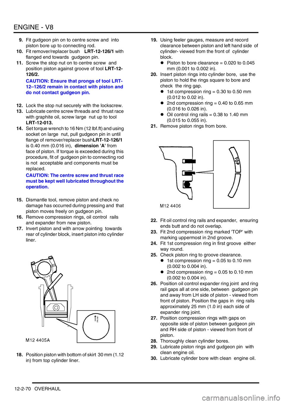
17.Invert piston and with arrow pointing towards
rear of cylinder block, insert piston into cylinder
liner.
18.Position piston with bottom of skirt 30 mm (1.12
in) from top cylinder liner. 19.Using feeler gauges, measure and record
clearance between piston and left hand side of
cylinder- viewed from the front of cylinder
block.
lPiston to bore clearance = 0.020 to 0.045
mm (0.001 to 0.002 in).
20.Insert piston rings into cylinder bore, use the
piston to hold the rings square to bore and
check the ring gap.
l1st compression ring = 0.30 to 0.50 mm
(0.012 to 0.02 in).
l2nd compression ring = 0.40 to 0.65 mm
(0.016 to 0.026 in).
lOil control ring rails = 0.38 to 1.40 mm
(0.015 to 0.055 in).
21.Remove piston rings from bore.
22.Fit oil control ring rails and expander, ensuring
ends butt and do not overlap.
23.Fit 2nd compression ring marked 'TOP' with
marking uppermost in 2nd groove.
24.Fit 1st compression ring in first groove either
way round.
25.Check piston ring to groove clearance.
l1st compression ring = 0.05 to 0.10 mm
(0.002 to 0.004 in).
l2nd compression ring = 0.05 to 0.10 mm
(0.002 to 0.004 in).
26.Position oil control expander ring joint and ring
rail gaps all at one side, between gudgeon pin
and away from LH side of piston - viewed from
front of piston. Position the gaps in ring rails
approximately 25 mm (1.0 in) each side of
expander ring joint.
27.Position compression rings with gaps on
opposite side of piston between gudgeon pin
and RH side of piston - viewed from front of
piston.
28.Thoroughly clean cylinder bores.
29.Lubricate piston rings and gudgeon pin with
clean engine oil.
30.Lubricate cylinder bore with clean engine oil.
Page 226 of 1529

ENGINE - V8
OVERHAUL 12-2-71
31.Using LRT-12-204, compress piston rings.
32.Insert connecting rod and piston into its
respective cylinder bore, ensuring domed
shaped boss on connecting rod faces towards
front of engine on RH bank of cylinders and
towards rear on LH bank of cylinders.
33.Clean connecting rod journal and bearing cap.
34.Lubricate connecting rod journal and
connecting rod bearings. 35.Fit connecting rod bearings and connecting rod
bearing caps ensuring they are in their correct
fitted order.
NOTE: The rib on the edge of the bearing cap
must face towards the front of the engine on the
RH bank of cylinders and towards the rear on
the LH bank.
36.Fit bolts and tighten to 20 Nm (15 lbf.ft) then
turn a further 80°.
37.Fit oil pick-up strainer.
+ ENGINE - V8, OVERHAUL, Strainer
- oil pick-up.
38.Fit cylinder head gasket.
+ ENGINE - V8, OVERHAUL, Gasket -
cylinder head.