engine coolant LAND ROVER DISCOVERY 1999 Owner's Guide
[x] Cancel search | Manufacturer: LAND ROVER, Model Year: 1999, Model line: DISCOVERY, Model: LAND ROVER DISCOVERY 1999Pages: 1529, PDF Size: 34.8 MB
Page 280 of 1529

EMISSION CONTROL - V8
DESCRIPTION AND OPERATION 17-2-47
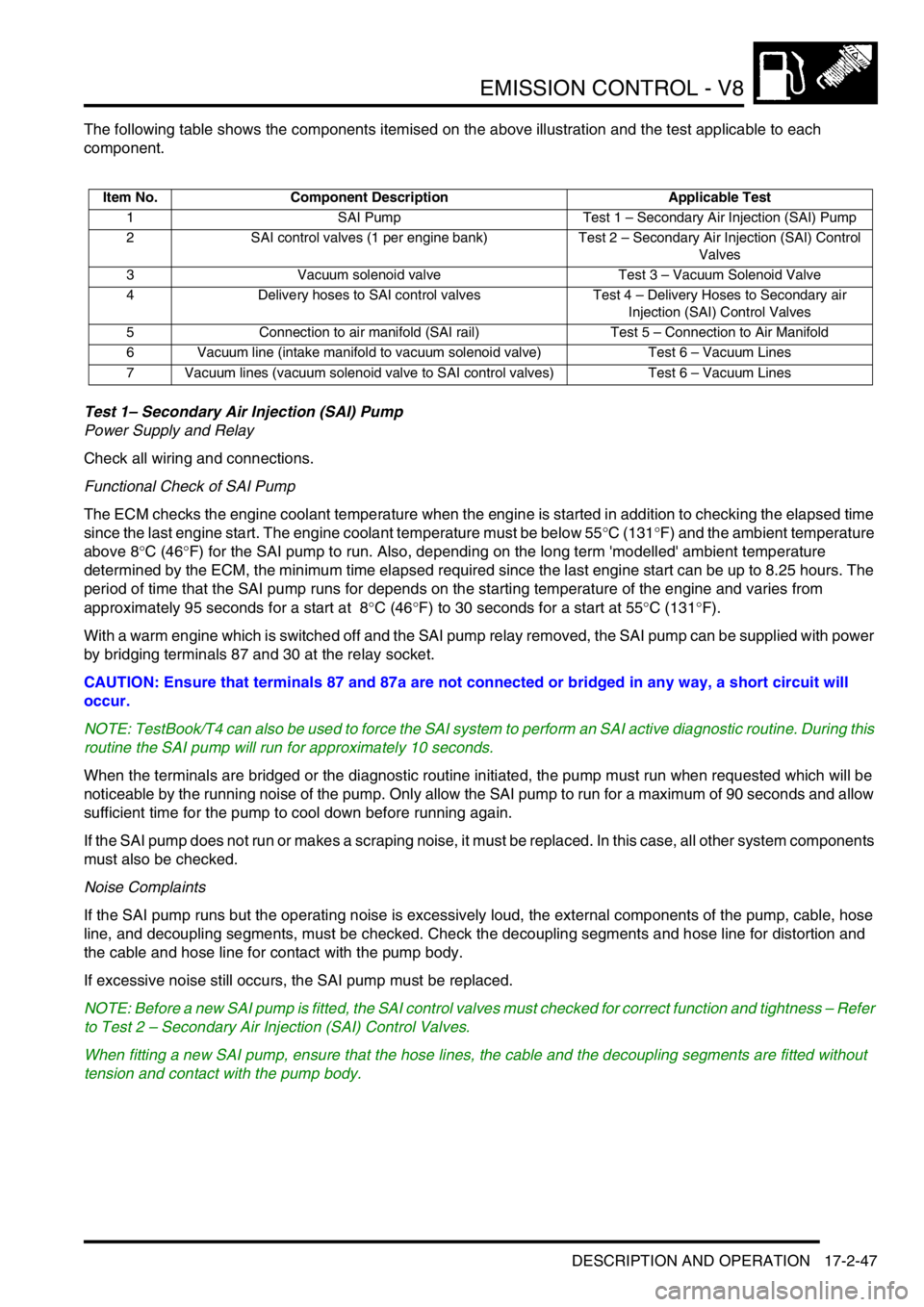
The following table shows the components itemised on the above illustration and the test applicable to each
component.
Test 1– Secondary Air Injection (SAI) Pump
Power Supply and Relay
Check all wiring and connections.
Functional Check of SAI Pump
The ECM checks the engine coolant temperature when the engine is started in addition to checking the elapsed time
since the last engine start. The engine coolant temperature must be below 55°C (131°F) and the ambient temperature
above 8°C (46°F) for the SAI pump to run. Also, depending on the long term 'modelled' ambient temperature
determined by the ECM, the minimum time elapsed required since the last engine start can be up to 8.25 hours. The
period of time that the SAI pump runs for depends on the starting temperature of the engine and varies from
approximately 95 seconds for a start at 8°C (46°F) to 30 seconds for a start at 55°C (131°F).
With a warm engine which is switched off and the SAI pump relay removed, the SAI pump can be supplied with power
by bridging terminals 87 and 30 at the relay socket.
CAUTION: Ensure that terminals 87 and 87a are not connected or bridged in any way, a short circuit will
occur.
NOTE: TestBook/T4 can also be used to force the SAI system to perform an SAI active diagnostic routine. During this
routine the SAI pump will run for approximately 10 seconds.
When the terminals are bridged or the diagnostic routine initiated, the pump must run when requested which will be
noticeable by the running noise of the pump. Only allow the SAI pump to run for a maximum of 90 seconds and allow
sufficient time for the pump to cool down before running again.
If the SAI pump does not run or makes a scraping noise, it must be replaced. In this case, all other system components
must also be checked.
Noise Complaints
If the SAI pump runs but the operating noise is excessively loud, the external components of the pump, cable, hose
line, and decoupling segments, must be checked. Check the decoupling segments and hose line for distortion and
the cable and hose line for contact with the pump body.
If excessive noise still occurs, the SAI pump must be replaced.
NOTE: Before a new SAI pump is fitted, the SAI control valves must checked for correct function and tightness – Refer
to Test 2 – Secondary Air Injection (SAI) Control Valves.
When fitting a new SAI pump, ensure that the hose lines, the cable and the decoupling segments are fitted without
tension and contact with the pump body.
Item No. Component Description Applicable Test
1 SAI Pump Test 1 – Secondary Air Injection (SAI) Pump
2 SAI control valves (1 per engine bank) Test 2 – Secondary Air Injection (SAI) Control
Valves
3 Vacuum solenoid valve Test 3 – Vacuum Solenoid Valve
4 Delivery hoses to SAI control valves Test 4 – Delivery Hoses to Secondary air
Injection (SAI) Control Valves
5 Connection to air manifold (SAI rail) Test 5 – Connection to Air Manifold
6 Vacuum line (intake manifold to vacuum solenoid valve) Test 6 – Vacuum Lines
7 Vacuum lines (vacuum solenoid valve to SAI control valves) Test 6 – Vacuum Lines
Page 296 of 1529

EMISSION CONTROL - V8
REPAIRS 17-2-63
8.Remove 2 nuts securing air injection pipe to air
intake plenum.
9.Release pipe from clip on rear of air intake
plenum.
10.Release 3 clips securing harness to engine bay
bulkhead.
11.Position container to collect any coolant
spillage.
12.Release clips securing heater hoses to heater.
13.Release hoses from heater.
14.With assistance, manoeuvre air injection pipe
from engine bay.Refit
1.With assistance, manoeuvre air injection pipe
into engine bay and secure onto clip at rear of
air intake plenum.
2.Connect heater hoses to heater and secure
with clips.
3.Reposition harness along engine bay bulkhead
and secure with clips.
4.Fit and tighten nuts securing air injection pipe to
air intake plenum.
5.Connect multiplug to SAI vacuum solenoid.
6.Connect air pump hose to air injection pipe and
secure with clip.
7.Connect LH and RH SAI control valve hoses to
air injection pipe and secure with clips.
8.Remove container.
9.Top up engine coolant.
+ MAINTENANCE, PROCEDURES,
Cooling system.
M17 0231
M17 0232
M17 0233
Page 302 of 1529

ENGINE MANAGEMENT SYSTEM - V8
DESCRIPTION AND OPERATION 18-2-3
1Mass air flow/ inlet air temperature sensor
2Fuel injectors
3High tension leads/spark plugs
4Fuel pump relay
5ATC compressor clutch relay/ cooling fan relay
6Throttle position sensor
7Heated oxygen sensor
8Idle air control valve
9Ignition coils
10Engine coolant temperature sensor
11Crankshaft speed and position sensor
12Knock sensor
13Camshaft position sensor
Page 304 of 1529

ENGINE MANAGEMENT SYSTEM - V8
DESCRIPTION AND OPERATION 18-2-5
1Engine control module
2Crankshaft speed and position sensor
3Camshaft position sensor
4Engine coolant temperature sensor
5Mass air flow/ inlet air temperature sensor
6Throttle position sensor
7Heated oxygen sensors
8Fuel injectors
9Idle air control valve
10Fuel pump relay
11EVAP canister
12EVAP canister vent valve
13EVAP canister purge valve
14Fuel tank pressure sensor15Ignition coils
16Knock sensor
17Spark plugs
18High/ Low ratio switch
19Malfunction indication lamp
20Diagnostic connector
21Air temperature control clutch relay
22Air temperature control cooling fan relay
23ATC ECU
24CAN link to EAT
25SLABS ECU
26BCU
27Instrument cluster
28Thermostat monitoring sensor (where fitted)
Page 305 of 1529

ENGINE MANAGEMENT SYSTEM - V8
18-2-6 DESCRIPTION AND OPERATION
Description - engine management
General
The V8 engine is equipped with the Bosch Motronic M5.2.1 engine management system. This system is a sequential
multiport fuel injection system controlled by an Engine Control Module (ECM).
A single ECM is used for the control of the existing 4.0 litre engine and the new 4.6 litre engine introduced with 03
model year vehicles for the NAS market only. The ECM contains the tunes for both engines variants. When the ECM
is replaced, TestBook/T4 must be used to select the correct tune to match the engine fitment.
The ECM has On Board Diagnostic (OBD) strategies as required by various market legislative bodies. To meet these
requirements the system monitors and reports on any faults that cause excessive exhaust emissions.
In markets that mandate OBD, the ECM monitors performance of the engine for misfires, catalyst efficiency, exhaust
leaks and evaporative control loss. If a fault occurs, the ECM stores the relevant fault code and warns the driver of
component failure by illuminating the Malfunction Indicator Light in the instrument pack.
In markets where OBD is not mandatory, the ECM will still monitor performance of the engine and store the fault code,
but will not illuminate the Malfunction Indicator Light.
The ECM uses input and output information from its sensors and actuators to control the following engine conditions:
lFuel quantity.
lClosed loop fuelling.
lOpen loop fuelling.
lIgnition timing.
lKnock control.
lIdle speed control.
lEmission control.
lOn-Board Diagnostic (OBD) where applicable.
lVehicle immobilisation.
lMisfire detection (where applicable).
lVehicle speed signal.
lRough road signal (where applicable).
lLow fuel level signal (where applicable).
lCoolant temperature gauge signal.
The ECM processes sensor information from the following input sources:
lIgnition switch (position II).
lCrankshaft speed and position sensor.
lCamshaft position sensor.
lEngine coolant temperature sensor.
lMass air flow sensor.
lIntake air temperature sensor.
lKnock sensor.
lThrottle position sensor.
lHeated oxygen sensors.
lHigh/ Low ratio switch.
lFuel tank pressure sensor (where fitted)
lThermostat monitoring sensor (where fitted)
Page 309 of 1529

ENGINE MANAGEMENT SYSTEM - V8
18-2-10 DESCRIPTION AND OPERATION
Connector 3 (C0636): This connector contains 52 pins and is used for most sensor and actuator inputs and outputs.
Sensor and actuator control is vital to ensure that the ECM maintains adaptive strategy
Pin out details connector C0636
Pin No. Function Signal type Reading
1 Injector cylinder number 2 Output Switch to earth
2 Injector cylinder number 5 Output Switch to earth
3 Purge valve Output, signal PWM 12-0V
4 SAI vacuum solenoid valve (NAS vehicles from 2000MY
only)Output Switch to earth
5 Not used - -
6 Fuel tank pressure sensor (NAS vehicles with vacuum type,
EVAP system leak detection only)Earth 0V
7 MAF sensor 5V supply Output, reference 5V
8 Not used - -
9 MAF sensor earth Earth 0V
10 TP sensor 5V supply Output, reference 5V
11 Not used - -
12 Not used - -
13 Not used - -
14 Injector cylinder number 7 Output Switch to earth
15 Injector cylinder number 6 Output Switch to earth
16 SAI pump relay (NAS vehicles from 2000MY only) Output Switch to earth
17 CMP sensor Earth 0V
18 Low range switch (manual transmission only) Input, signal Active low
19 Not used - -
20 CMP signal Input, signal Digital switch 0-12V
21 ECT sensor Earth 0V
22 Coolant temperature signal Input, signal Analogue 0-5V
23 MAF sensor signal Input, signal Analogue 0-5V
24 TP sensor signal Input, signal Analogue 0-5V
25 TP sensor earth Earth 0V
26 Not used - -
27 Injector cylinder number 3 Output Switch to earth
28 Injector cylinder number 8 Output Switch to earth
29 Hill decent control output Output, signal PWM 0-12V
30 EVAP canister vent solenoid (CVS) valve (NAS vehicles with
vacuum type, EVAP system leak detection only)Output Switch to earth
30 Leak detection pump solenoid (NAS vehicles with positive
pressure type, EVAP system leak detection only)Output Switch to earth
31 A/C condenser fan Output Switch to earth
32 CKP sensor signal Input, signal Analogue, 0-300V peak
33 Not used - -
34 IAT sensor signal Input, signal Analogue 0-5V
35 KS, RH bank earth Earth 0V
36 KS, RH bank signal Input, signal Analogue
37 Not used - -
38 Not used - -
39 Not used - -
40 Injector cylinder number 4 Output Switch to earth
41 Injector cylinder number 1 Output Switch to earth
42 Idle air control valve open Output, signal PWM 12-0V
43 Idle air control valve close Output, signal PWM 12-0V
44 ECT sensor signal Output, signal PWM 0-12V
Page 317 of 1529

ENGINE MANAGEMENT SYSTEM - V8
18-2-18 DESCRIPTION AND OPERATION
Engine Coolant Temperature (ECT) sensor (C0196)
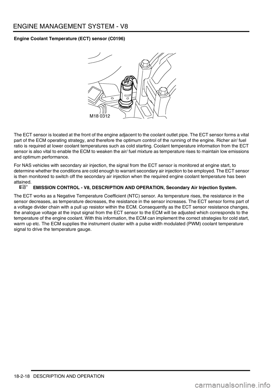
The ECT sensor is located at the front of the engine adjacent to the coolant outlet pipe. The ECT sensor forms a vital
part of the ECM operating strategy, and therefore the optimum control of the running of the engine. Richer air/ fuel
ratio is required at lower coolant temperatures such as cold starting. Coolant temperature information from the ECT
sensor is also vital to enable the ECM to weaken the air/ fuel mixture as temperature rises to maintain low emissions
and optimum performance.
For NAS vehicles with secondary air injection, the signal from the ECT sensor is monitored at engine start, to
determine whether the conditions are cold enough to warrant secondary air injection to be employed. The ECT sensor
is then monitored to switch off the secondary air injection when the required engine coolant temperature has been
attained.
+ EMISSION CONTROL - V8, DESCRIPTION AND OPERATION, Secondary Air Injection System.
The ECT works as a Negative Temperature Coefficient (NTC) sensor. As temperature rises, the resistance in the
sensor decreases, as temperature decreases, the resistance in the sensor increases. The ECT sensor forms part of
a voltage divider chain with a pull up resistor within the ECM. Consequently as the ECT sensor resistance changes,
the analogue voltage at the input signal from the ECT sensor to the ECM will be adjusted which corresponds to the
temperature of the engine coolant. With this information, the ECM can implement the correct strategies for cold start,
warm up etc. The ECM supplies the instrument cluster with a pulse width modulated (PWM) coolant temperature
signal to drive the temperature gauge.
Page 319 of 1529

ENGINE MANAGEMENT SYSTEM - V8
18-2-20 DESCRIPTION AND OPERATION
There are three types of ECT sensor diagnostic checks:
lThe ECT sensor signal is within limits, but is inaccurate – the engine has to be running and the signal indicates
a coolant temperature below 40°C (104°F). The signal differs too much from the coolant temperature model for
longer than 2.53 seconds.
lThe ECT sensor signal is greater than the maximum threshold value – the ECM has to be powered up to perform
the diagnostic, but the engine does not need to be running.
lThe ECT sensor signal is less than the minimum threshold value – the ECM has to be powered up to perform
the diagnostic, but the engine does not need to be running.
Should a malfunction of the component occur the following fault codes may be evident and can be retrieved by
TestBook:
P code J2012 description Land Rover description
P0116 Engine coolant temperature circuit/range
performance problemSignal differs too much from temperature model for
longer than 2.53s
P0117 Engine coolant temperature circuit low input Open circuit or short circuit to battery supply
P0118 Engine coolant temperature circuit high input Short circuit to earth
Page 321 of 1529

ENGINE MANAGEMENT SYSTEM - V8
18-2-22 DESCRIPTION AND OPERATION
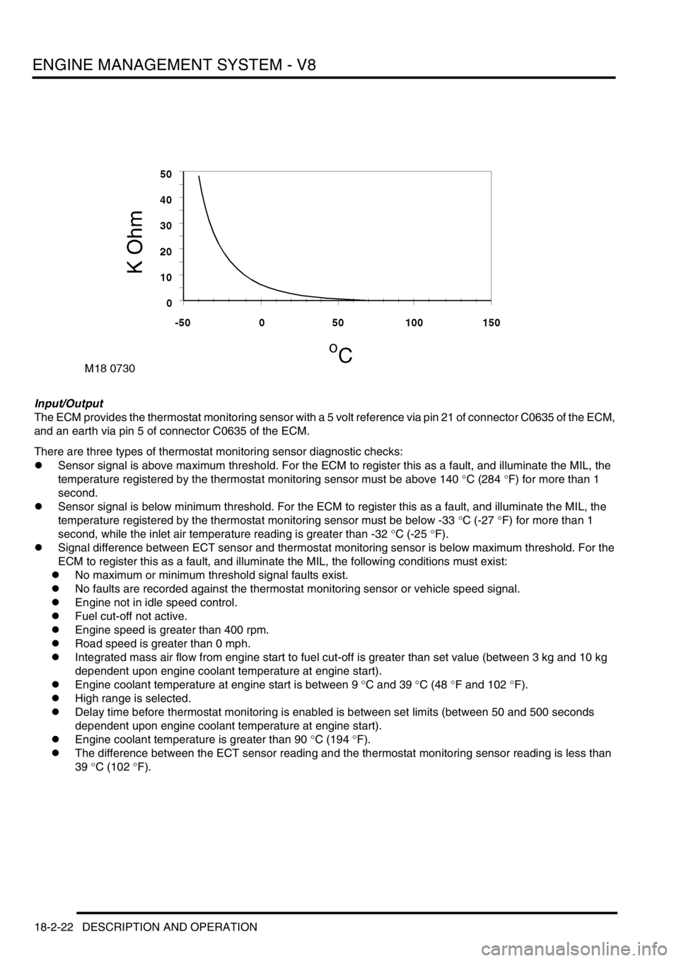
Input/Output
The ECM provides the thermostat monitoring sensor with a 5 volt reference via pin 21 of connector C0635 of the ECM,
and an earth via pin 5 of connector C0635 of the ECM.
There are three types of thermostat monitoring sensor diagnostic checks:
lSensor signal is above maximum threshold. For the ECM to register this as a fault, and illuminate the MIL, the
temperature registered by the thermostat monitoring sensor must be above 140 °C (284 °F) for more than 1
second.
lSensor signal is below minimum threshold. For the ECM to register this as a fault, and illuminate the MIL, the
temperature registered by the thermostat monitoring sensor must be below -33 °C (-27 °F) for more than 1
second, while the inlet air temperature reading is greater than -32 °C (-25 °F).
lSignal difference between ECT sensor and thermostat monitoring sensor is below maximum threshold. For the
ECM to register this as a fault, and illuminate the MIL, the following conditions must exist:
lNo maximum or minimum threshold signal faults exist.
lNo faults are recorded against the thermostat monitoring sensor or vehicle speed signal.
lEngine not in idle speed control.
lFuel cut-off not active.
lEngine speed is greater than 400 rpm.
lRoad speed is greater than 0 mph.
lIntegrated mass air flow from engine start to fuel cut-off is greater than set value (between 3 kg and 10 kg
dependent upon engine coolant temperature at engine start).
lEngine coolant temperature at engine start is between 9 °C and 39 °C (48 °F and 102 °F).
lHigh range is selected.
lDelay time before thermostat monitoring is enabled is between set limits (between 50 and 500 seconds
dependent upon engine coolant temperature at engine start).
lEngine coolant temperature is greater than 90 °C (194 °F).
lThe difference between the ECT sensor reading and the thermostat monitoring sensor reading is less than
39 °C (102 °F).
Page 322 of 1529

ENGINE MANAGEMENT SYSTEM - V8
DESCRIPTION AND OPERATION 18-2-23
Should a malfunction occur, the following fault codes may be evident and can be retrieved by TestBook:
Mass Air Flow (MAF)/ Inlet Air Temperature (IAT) sensor (C0149)
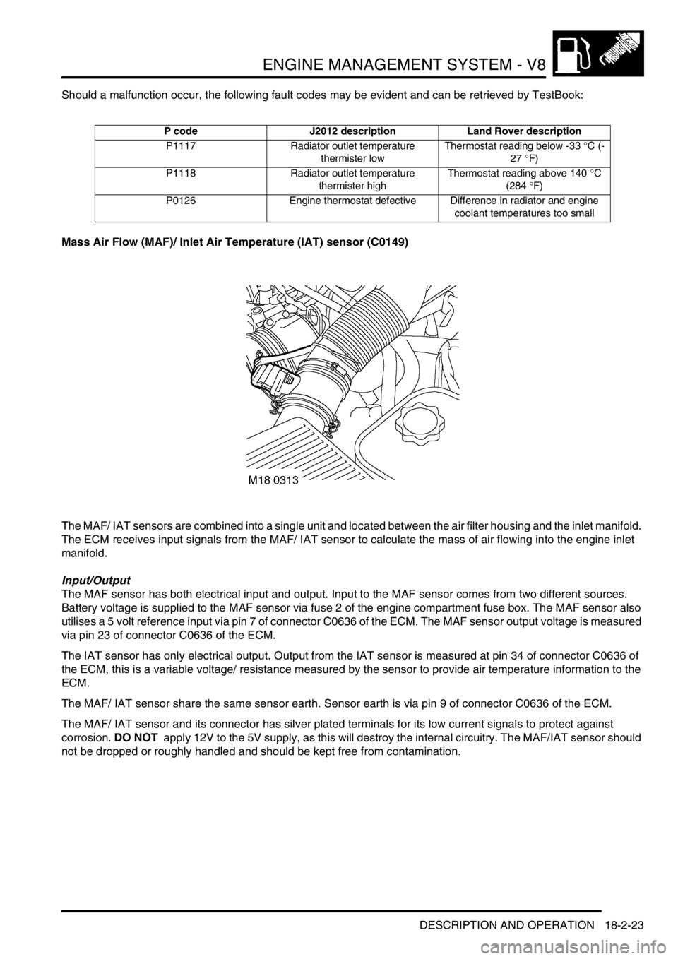
The MAF/ IAT sensors are combined into a single unit and located between the air filter housing and the inlet manifold.
The ECM receives input signals from the MAF/ IAT sensor to calculate the mass of air flowing into the engine inlet
manifold.
Input/Output
The MAF sensor has both electrical input and output. Input to the MAF sensor comes from two different sources.
Battery voltage is supplied to the MAF sensor via fuse 2 of the engine compartment fuse box. The MAF sensor also
utilises a 5 volt reference input via pin 7 of connector C0636 of the ECM. The MAF sensor output voltage is measured
via pin 23 of connector C0636 of the ECM.
The IAT sensor has only electrical output. Output from the IAT sensor is measured at pin 34 of connector C0636 of
the ECM, this is a variable voltage/ resistance measured by the sensor to provide air temperature information to the
ECM.
The MAF/ IAT sensor share the same sensor earth. Sensor earth is via pin 9 of connector C0636 of the ECM.
The MAF/ IAT sensor and its connector has silver plated terminals for its low current signals to protect against
corrosion. DO NOT apply 12V to the 5V supply, as this will destroy the internal circuitry. The MAF/IAT sensor should
not be dropped or roughly handled and should be kept free from contamination.
P code J2012 description Land Rover description
P1117 Radiator outlet temperature
thermister lowThermostat reading below -33 °C (-
27 °F)
P1118 Radiator outlet temperature
thermister highThermostat reading above 140 °C
(284 °F)
P0126 Engine thermostat defective Difference in radiator and engine
coolant temperatures too small