light LAND ROVER DISCOVERY 1999 Manual PDF
[x] Cancel search | Manufacturer: LAND ROVER, Model Year: 1999, Model line: DISCOVERY, Model: LAND ROVER DISCOVERY 1999Pages: 1529, PDF Size: 34.8 MB
Page 846 of 1529

REAR SUSPENSION
REPAIRS 64-37
Filter - intake - SLS
$% 64.50.12
Remove
1.Remove LH tail lamp.
+ LIGHTING, REPAIRS, Lamp - tail.
2.Disconnect filter from retaining peg.
3.Disconnect quick release connection and
remove filter assembly.
Refit
1.Position filter assembly and connect quick
release connection.
2.Secure filter retaining peg.
3.Fit LH tail lamp.
+ LIGHTING, REPAIRS, Lamp - tail.
Switch - ride height
$% 64.50.45
Remove
1.Carefully remove switch.
2.Disconnect multiplug from switch.
3.Remove switch.
Refit
1.Connect multiplug switch.
2.Position switch and push to secure.
Page 873 of 1529
BRAKES
70-20 DESCRIPTION AND OPERATION
Operation
Refer to illustration.
+ BRAKES, DESCRIPTION AND OPERATION, Brake system control diagram.
When the ignition is switched on, the SLABS ECU performs a check of the brake related warning lamps as part of the
power up procedure. The warning lamps are illuminated for approximately 3 seconds and then extinguished. If a fault
warning lamp remains illuminated after the lamp check, a fault has been detected and repair action is required.
ABS
The ABS function prevents the road wheels locking during brake application, thus maintaining vehicle stability even
under emergency conditions.
WARNING: ABS is an aid to retaining steering control and stability while braking:
lABS cannot defy the natural laws of physics acting on the vehicle.
lABS will not prevent accidents resulting from excessive cornering speeds, following another vehicle too
closely, aquaplaning, etc.
lThe additional control provided by ABS must never be exploited in a dangerous or reckless manner
which could jeopardise the safety of driver or other road users.
lThe fitting of ABS does not imply that the vehicle will always stop in a shorter distance.
NOTE: During normal braking the feel of the brake pedal on vehicles equipped with ABS will be the same as that on
non ABS vehicles. During anti-lock braking operation the driver will experience feedback in the form of a pulsating
brake pedal and solenoid/pump motor noise from the ABS modulator.
The anti-lock braking function is automatically enabled whenever the ABS modulator is in the normal braking mode.
While the anti-lock braking function is enabled, if the SLABS ECU detects a wheel decelerating faster than the
average and at the calibrated wheel slip limit for ABS operation, it operates the ABS modulator in the ABS braking
mode for the affected wheel.
EBD
The EBD function optimises the distribution of hydraulic pressure between the front and rear axles, under all vehicle
load configurations and road conditions, to maintain vehicle stability during braking. EBD operates in forward and
reverse and is automatically enabled whenever the ABS modulator is in the normal braking mode at vehicle
deceleration rates of 0.3 g and above (i.e. medium to high brake pedal loads). EBD operation is similar to that of ABS,
but is calibrated to intervene at lower wheel slip limits and operates the brakes in axle pairs instead of individually.
During braking, if the SLABS ECU detects the wheels of one axle going slower than those of the other axle, i.e. a
potential wheel slip situation, it signals the ABS modulator to close the inlet solenoid valve for the brakes of the slower
wheels. This prevents any further increase in hydraulic pressure to those brakes, while allowing the hydraulic pressure
to the brakes on the other axle to increase and so maximise the overall braking effort. If the wheel speeds of the axle
being subjected to EBD control return within the calibrated wheel slip limits, the SLABS ECU signals a stepped
opening of the inlet solenoid valves, which allows a progressive increase of hydraulic pressure to the related brakes.
Operation of EBD is detectable from a stiffening of brake pedal movement as the inlet solenoid valves close and a
slight pulsing of the brake pedal as the inlet solenoid valves open. EBD operation ceases immediately the brake pedal
is released.
The wheel slip limit for EBD operation varies with vehicle speed. During normal operation, the inlet solenoid valves
always operate in axle pairs, with only one axle pair closed at any one time. Since the most lightly loaded wheel during
a braking manoeuvre will usually be the first to reach the slip limit, under most vehicle load configurations and road
conditions EBD control occurs on the trailing axle. However, EBD control can occur on the leading axle or switch
between axles during the braking manoeuvre.
Page 890 of 1529
BRAKES
REPAIRS 70-37
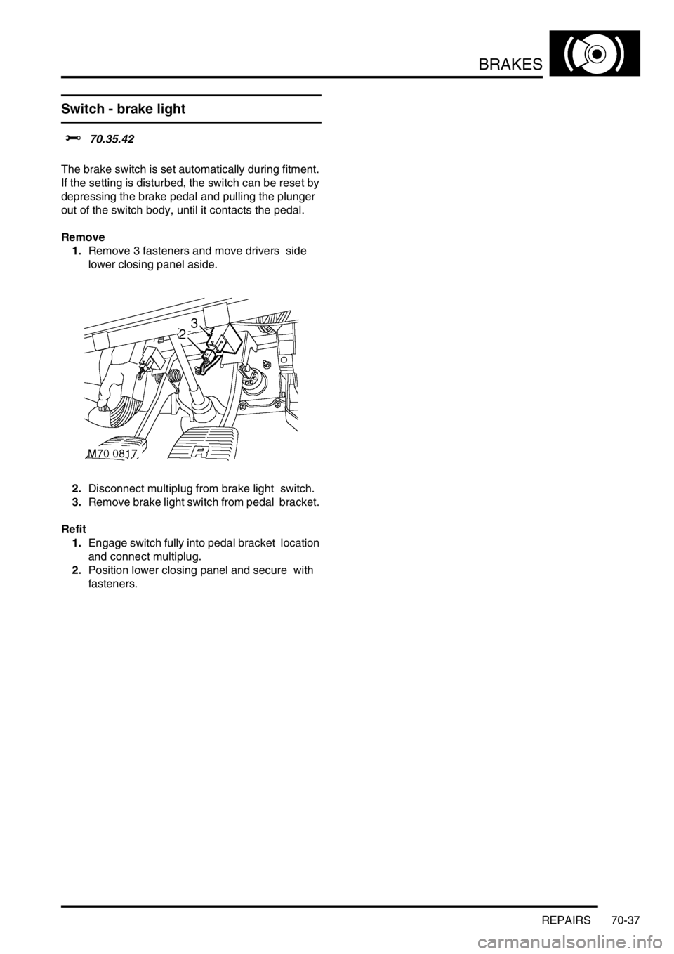
Switch - brake light
$% 70.35.42
The brake switch is set automatically during fitment.
If the setting is disturbed, the switch can be reset by
depressing the brake pedal and pulling the plunger
out of the switch body, until it contacts the pedal.
Remove
1.Remove 3 fasteners and move drivers side
lower closing panel aside.
2.Disconnect multiplug from brake light switch.
3.Remove brake light switch from pedal bracket.
Refit
1.Engage switch fully into pedal bracket location
and connect multiplug.
2.Position lower closing panel and secure with
fasteners.
Page 939 of 1529
DOORS
76-1-6 REPAIRS
Quarter light
$% 76.31.31
Remove
1.Remove rear door glass.
+ DOORS, REPAIRS, Glass - front or
rear door.
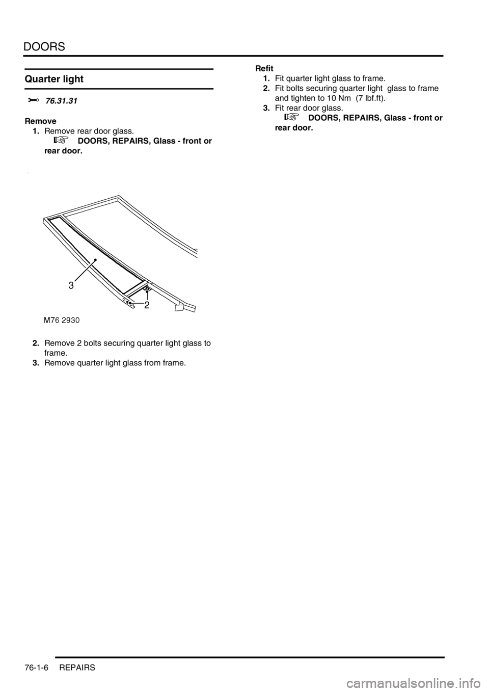
2.Remove 2 bolts securing quarter light glass to
frame.
3.Remove quarter light glass from frame. Refit
1.Fit quarter light glass to frame.
2.Fit bolts securing quarter light glass to frame
and tighten to 10 Nm (7 lbf.ft).
3.Fit rear door glass.
+ DOORS, REPAIRS, Glass - front or
rear door.
Page 948 of 1529
EXTERIOR FITTINGS
REPAIRS 76-2-1
EXTERIOR FITTINGS REPAIRS
Wing - front - up to 03MY
$% 76.10.24
Remove
1.Remove front repeater lamp.
+ LIGHTING, REPAIRS, Lamp - front
repeater - up to 03MY.
2.Remove front wheel arch liner.
+ EXTERIOR FITTINGS, REPAIRS,
Liner - wheel arch - front.
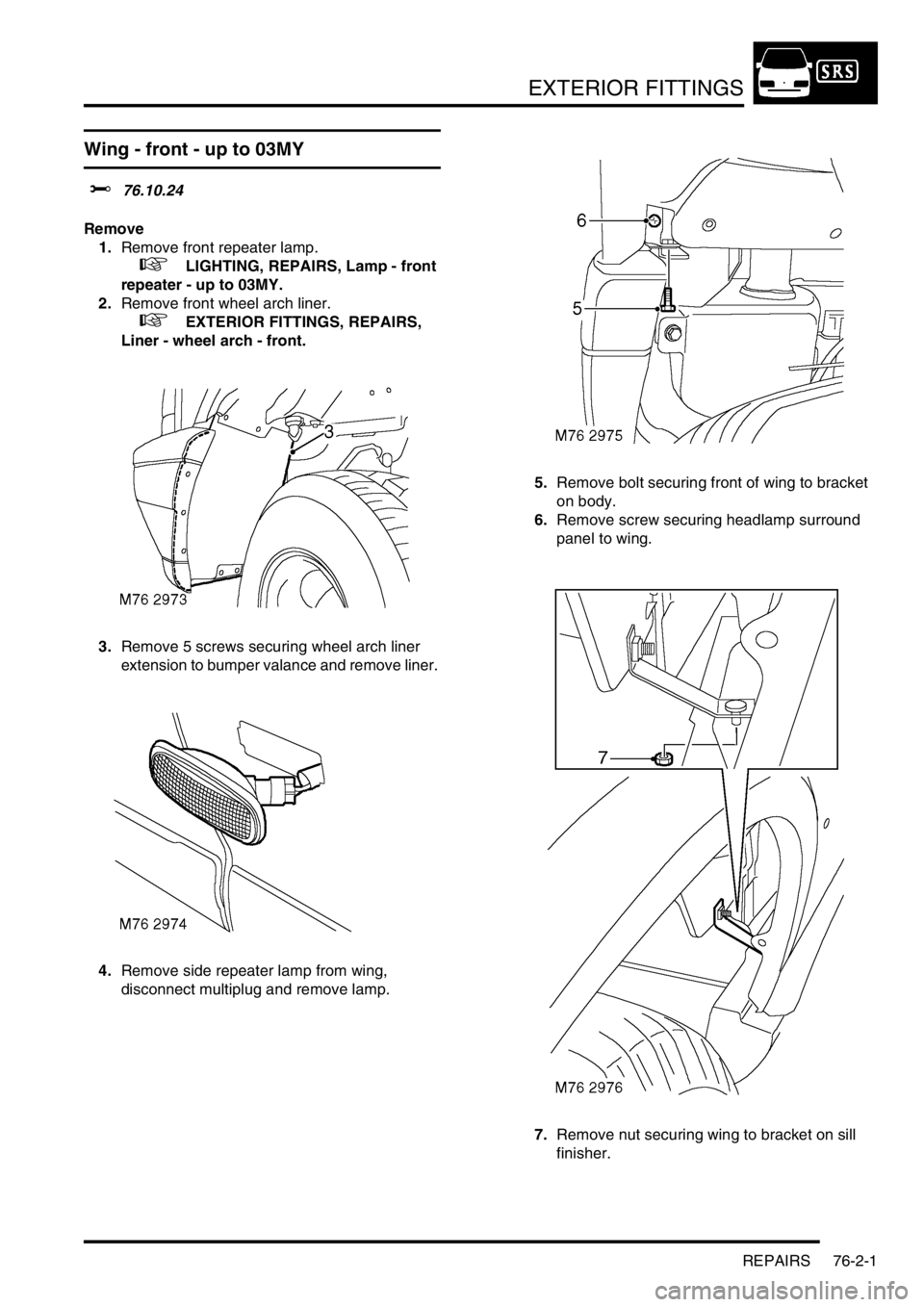
3.Remove 5 screws securing wheel arch liner
extension to bumper valance and remove liner.
4.Remove side repeater lamp from wing,
disconnect multiplug and remove lamp.5.Remove bolt securing front of wing to bracket
on body.
6.Remove screw securing headlamp surround
panel to wing.
7.Remove nut securing wing to bracket on sill
finisher.
Page 949 of 1529
EXTERIOR FITTINGS
76-2-2 REPAIRS
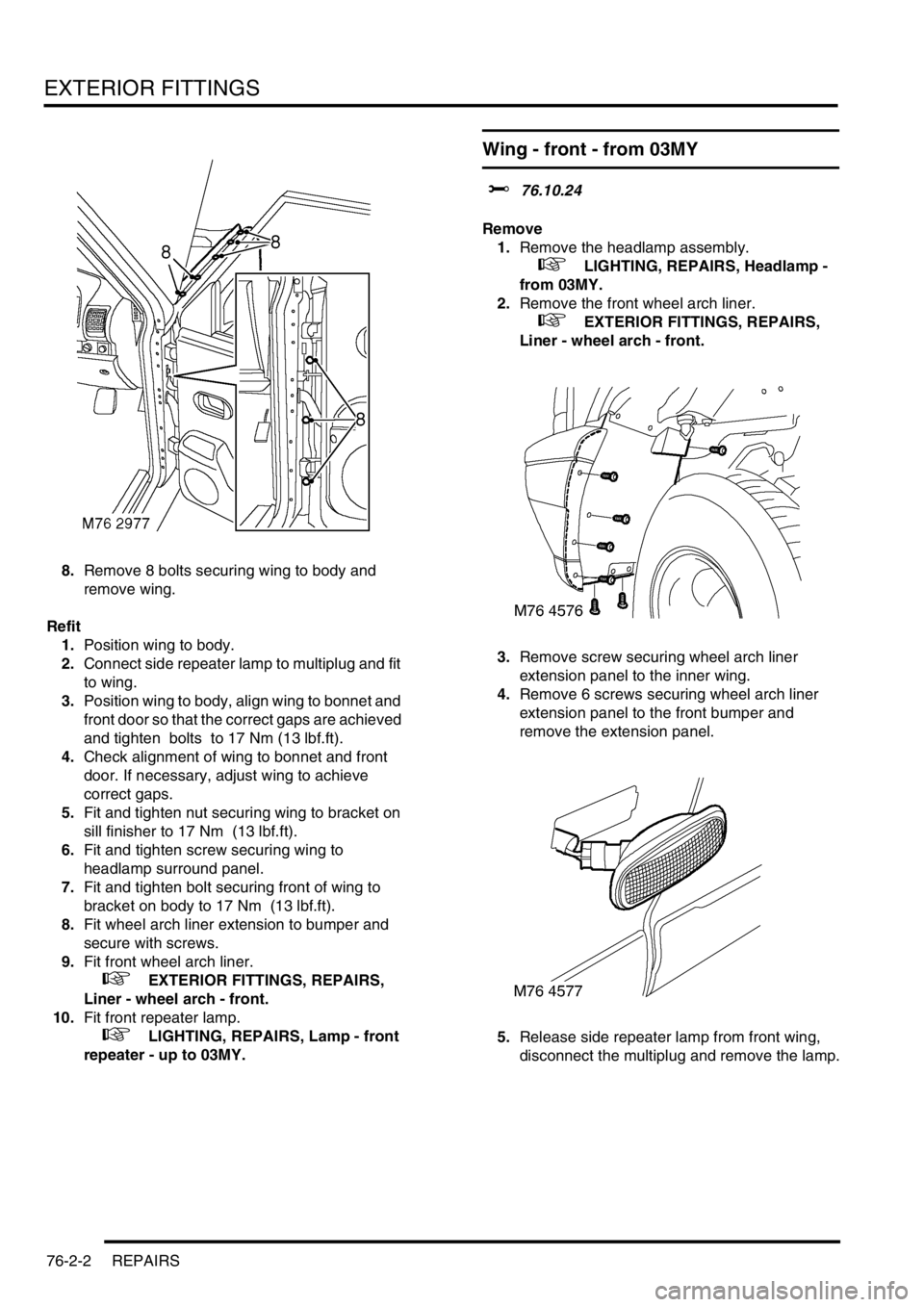
8.Remove 8 bolts securing wing to body and
remove wing.
Refit
1.Position wing to body.
2.Connect side repeater lamp to multiplug and fit
to wing.
3.Position wing to body, align wing to bonnet and
front door so that the correct gaps are achieved
and tighten bolts to 17 Nm (13 lbf.ft).
4.Check alignment of wing to bonnet and front
door. If necessary, adjust wing to achieve
correct gaps.
5.Fit and tighten nut securing wing to bracket on
sill finisher to 17 Nm (13 lbf.ft).
6.Fit and tighten screw securing wing to
headlamp surround panel.
7.Fit and tighten bolt securing front of wing to
bracket on body to 17 Nm (13 lbf.ft).
8.Fit wheel arch liner extension to bumper and
secure with screws.
9.Fit front wheel arch liner.
+ EXTERIOR FITTINGS, REPAIRS,
Liner - wheel arch - front.
10.Fit front repeater lamp.
+ LIGHTING, REPAIRS, Lamp - front
repeater - up to 03MY.
Wing - front - from 03MY
$% 76.10.24
Remove
1.Remove the headlamp assembly.
+ LIGHTING, REPAIRS, Headlamp -
from 03MY.
2.Remove the front wheel arch liner.
+ EXTERIOR FITTINGS, REPAIRS,
Liner - wheel arch - front.
3.Remove screw securing wheel arch liner
extension panel to the inner wing.
4.Remove 6 screws securing wheel arch liner
extension panel to the front bumper and
remove the extension panel.
5.Release side repeater lamp from front wing,
disconnect the multiplug and remove the lamp.
Page 951 of 1529
EXTERIOR FITTINGS
76-2-4 REPAIRS
Refit
1.Clean front wing body mounting brackets.
2.Fit and secure the front wheel arch finisher to
the front wing.
3.Position lower support bracket to the front wing,
fit nut and tighten to 8 Nm (6 lbf.ft).
4.Position front wing to body, fit bracket and bolts
but do not tighten at this stage.
5.Check and adjust alignment of the front wing to
the bonnet and door.
6.Tighten the front wing retaining bolts to 8 Nm (6
lbf.ft).
7.Fit bonnet sealing rubber to the front wing
flange.
8.Fit bolt securing lower support bracket to the
body and tighten to 8 Nm (6 lbf.ft).
9.Fit nut securing sill finisher to the front wing
lower support bracket and tighten to 8 Nm (6
lbf.ft).
10.Fit bolt securing front wing to the front support
bracket and tighten to 8 Nm (6 lbf.ft).
11.Fit side repeater lamp to the front wing and
connect the multiplug.
12.Fit front wheel arch liner extension panel to the
front bumper and secure with screws.
13.Fit and tighten screw securing front wheel arch
liner extension panel to the inner wing.
14.Fit the front wheel arch liner.
+ EXTERIOR FITTINGS, REPAIRS,
Liner - wheel arch - front.
15.Fit the headlamp assembly.
+ LIGHTING, REPAIRS, Headlamp -
from 03MY.
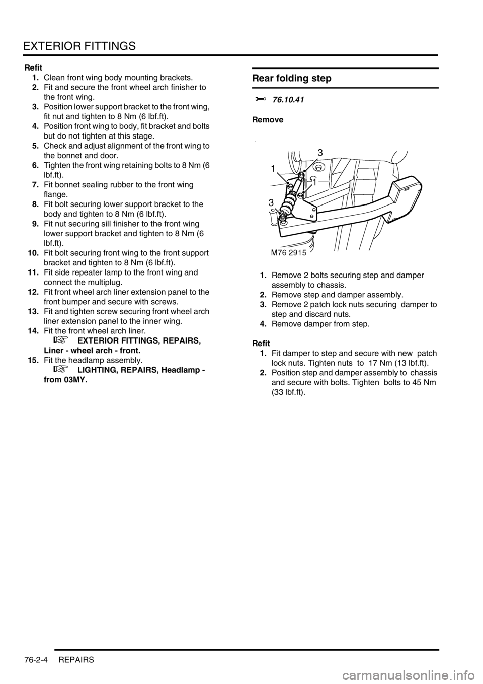
Rear folding step
$% 76.10.41
Remove
1.Remove 2 bolts securing step and damper
assembly to chassis.
2.Remove step and damper assembly.
3.Remove 2 patch lock nuts securing damper to
step and discard nuts.
4.Remove damper from step.
Refit
1.Fit damper to step and secure with new patch
lock nuts. Tighten nuts to 17 Nm (13 lbf.ft).
2.Position step and damper assembly to chassis
and secure with bolts. Tighten bolts to 45 Nm
(33 lbf.ft).
Page 956 of 1529
EXTERIOR FITTINGS
REPAIRS 76-2-9
Bonnet
$% 76.16.01.99
Remove
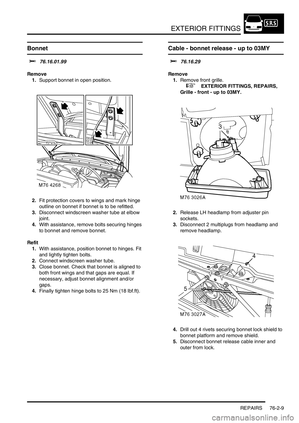
1.Support bonnet in open position.
2.Fit protection covers to wings and mark hinge
outline on bonnet if bonnet is to be refitted.
3.Disconnect windscreen washer tube at elbow
joint.
4.With assistance, remove bolts securing hinges
to bonnet and remove bonnet.
Refit
1.With assistance, position bonnet to hinges. Fit
and lightly tighten bolts.
2.Connect windscreen washer tube.
3.Close bonnet. Check that bonnet is aligned to
both front wings and that gaps are equal. If
necessary, adjust bonnet alignment and/or
gaps.
4.Finally tighten hinge bolts to 25 Nm (18 lbf.ft).
Cable - bonnet release - up to 03MY
$% 76.16.29
Remove
1.Remove front grille.
+ EXTERIOR FITTINGS, REPAIRS,
Grille - front - up to 03MY.
2.Release LH headlamp from adjuster pin
sockets.
3.Disconnect 2 multiplugs from headlamp and
remove headlamp.
4.Drill out 4 rivets securing bonnet lock shield to
bonnet platform and remove shield.
5.Disconnect bonnet release cable inner and
outer from lock.
Page 960 of 1529

EXTERIOR FITTINGS
REPAIRS 76-2-13
Bumper assembly - rear - from 03MY
$% 76.22.15
Remove
1.Remove both rear tail lamps.
+ LIGHTING, REPAIRS, Lamp - tail/
flasher - bumper.
2.Disconnect park distance control harness
multiplug.
3.Release rear lamp harness clips.4.Remove 2 bolts securing bumper.
5.With assistance remove bumper.
NOTE: Do not carry out further dismantling if
component is removed for access only.
6.Remove 7 bolts and 5 screws securing closing
panel and remove panel.
M76 4566
Page 961 of 1529
EXTERIOR FITTINGS
76-2-14 REPAIRS
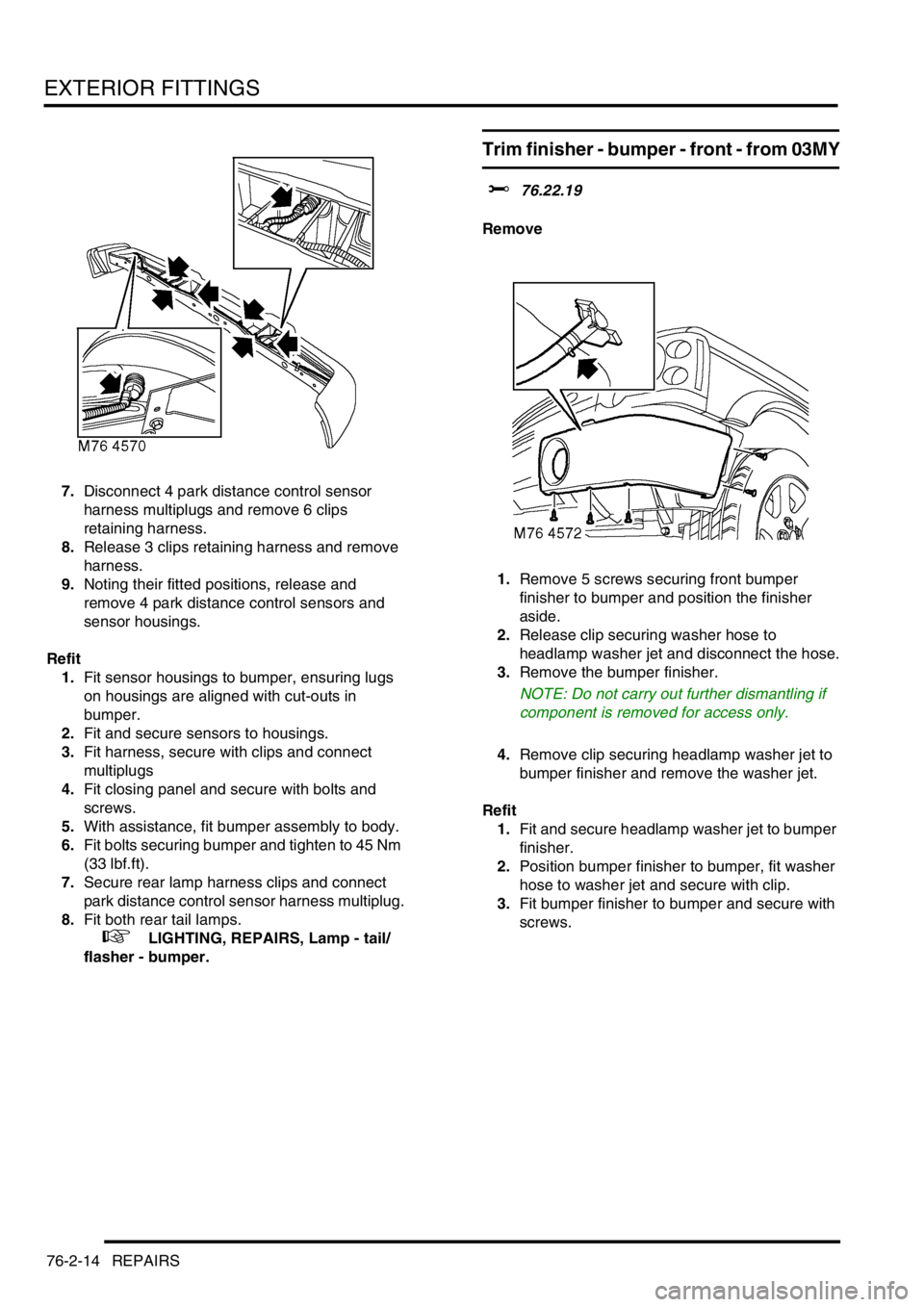
7.Disconnect 4 park distance control sensor
harness multiplugs and remove 6 clips
retaining harness.
8.Release 3 clips retaining harness and remove
harness.
9.Noting their fitted positions, release and
remove 4 park distance control sensors and
sensor housings.
Refit
1.Fit sensor housings to bumper, ensuring lugs
on housings are aligned with cut-outs in
bumper.
2.Fit and secure sensors to housings.
3.Fit harness, secure with clips and connect
multiplugs
4.Fit closing panel and secure with bolts and
screws.
5.With assistance, fit bumper assembly to body.
6.Fit bolts securing bumper and tighten to 45 Nm
(33 lbf.ft).
7.Secure rear lamp harness clips and connect
park distance control sensor harness multiplug.
8.Fit both rear tail lamps.
+ LIGHTING, REPAIRS, Lamp - tail/
flasher - bumper.
Trim finisher - bumper - front - from 03MY
$% 76.22.19
Remove
1.Remove 5 screws securing front bumper
finisher to bumper and position the finisher
aside.
2.Release clip securing washer hose to
headlamp washer jet and disconnect the hose.
3.Remove the bumper finisher.
NOTE: Do not carry out further dismantling if
component is removed for access only.
4.Remove clip securing headlamp washer jet to
bumper finisher and remove the washer jet.
Refit
1.Fit and secure headlamp washer jet to bumper
finisher.
2.Position bumper finisher to bumper, fit washer
hose to washer jet and secure with clip.
3.Fit bumper finisher to bumper and secure with
screws.