light LAND ROVER DISCOVERY 1999 Repair Manual
[x] Cancel search | Manufacturer: LAND ROVER, Model Year: 1999, Model line: DISCOVERY, Model: LAND ROVER DISCOVERY 1999Pages: 1529, PDF Size: 34.8 MB
Page 358 of 1529
ENGINE MANAGEMENT SYSTEM - V8
DESCRIPTION AND OPERATION 18-2-59
⇒ Drive cycle C:
1Switch ignition on for 30 seconds.
2Ensure engine coolant temperature is less than 60°C (140°F).
3Start the engine and allow to idle for 2 minutes.
4Perform 2 light accelerations (0 to 35 mph (0 to 60 km/h) with light pedal pressure).
5Perform 2 medium accelerations (0 to 45 mph (0 to 70 km/h) with moderate pedal pressure).
6Perform 2 hard accelerations (0 to 55 mph (0 to 90 km/h) with heavy pedal pressure).
7Cruise at 60 mph (100 km/h) for 8 minutes.
8Cruise at 50 mph (80 km/h) for 3 minutes.
9Allow engine to idle for 3 minutes.
10Connect TestBook and with the engine still running, check for fault codes.
NOTE: The following areas have an associated readiness test which must be flagged as complete, before a problem
resolution can be verified:
lcatalytic converter fault;
lEvaporative loss system fault;
lHO
2 sensor fault;
lHO
2 sensor heater fault.
When carrying out a drive cycle C to determine a fault in any of the above areas, select the readiness test icon to
verify that the test has been flagged as complete.
⇒ Drive cycle D:
1Switch ignition on for 30 seconds.
2Ensure engine coolant temperature is less than 35°C (95°F).
3Start the engine and allow to idle for 2 minutes.
4Perform 2 light accelerations (0 to 35 mph (0 to 60 km/h) with light pedal pressure).
5Perform 2 medium accelerations (0 to 45 mph (0 to 70 km/h) with moderate pedal pressure).
6Perform 2 hard accelerations (0 to 55 mph (0 to 90 km/h) with heavy pedal pressure).
7Cruise at 60 mph (100 km/h) for 5 minutes.
8Cruise at 50 mph (80 km/h) for 5 minutes.
9Cruise at 35 mph (60 km/h) for 5 minutes.
10Allow engine to idle for 2 minutes.
11Connect TestBook and check for fault codes.
⇒ Drive cycle E:
1Ensure fuel tank is at least a quarter full.
2Carry out Drive Cycle A.
3Switch off ignition.
4Leave vehicle undisturbed for 20 minutes.
5Switch on ignition.
6Connect TestBook and check for fault codes.
Page 405 of 1529

FUEL DELIVERY SYSTEM - V8
19-2-8 DESCRIPTION AND OPERATION
Fuel gauge sender
The fuel gauge sender unit comprises a rotary potentiometer operated by a float. The float rises and falls with the fuel
level in the tank and moves the potentiometer accordingly.
Battery voltage is supplied to the potentiometer. The output voltage from the potentiometer varies according to the
resistance through the potentiometer in relation to the fuel level. The output voltage is connected to the fuel gauge in
the instrument pack. The fuel gauge receives a battery voltage input and this is compared with the output voltage from
the potentiometer. The difference between the two voltages determines the deflection of the fuel gauge pointer.
Fuel gauge reading Tank volume litres (US Gallons) * Sender unit resistance
ohms Ω
FULL 95 (25) 15
3/4 71 (18.8) 36
1/2 48 (12.7) 64
1/4 24 (6.4) 110
RESERVE (fuel light ON) 11 (2.9) 158
EMPTY 0 (0) 245
*Tank volumes are approximate.
Page 421 of 1529

COOLING SYSTEM - V8
26-2-6 DESCRIPTION AND OPERATION
Description
General
The cooling system used on the V8 engine is a pressure relief by-pass type system which allows coolant to circulate
around the cylinder block and the heater circuit when the thermostat is closed. With coolant not passing through the
radiator, this promotes faster heater warm-up which in turn improves passenger comfort.
A coolant pump is located in a housing at the front of the engine and is driven by a drive belt. The pump is connected
into the coolant passages cast in the cylinder block and pumps coolant from the radiator through the cylinder block.
A viscous fan is attached by means of a nut to the coolant pump pulley drive spindle. The fan draws air through the
radiator to assist in cooling when the vehicle is stationary. The fan rotational speed is controlled relative to the running
temperature of the engine by a thermostatic valve regulated by a bi-metallic coil.
The cooling system uses a 50/50 mix of anti-freeze and water.
Thermostat housing
A plastic thermostat housing is located behind the radiator. The housing has three connections which locate the
radiator bottom hose, top hose and coolant pump feed hose. The housing contains a wax element and a spring loaded
by-pass flow valve.
Thermostat - Main valve
The thermostat is used to maintain the coolant at the optimum temperature for efficient combustion and to aid engine
warm-up. The thermostat is closed at temperatures below approximately 82°C (179°F). When the coolant
temperature reaches approximately 82°C the thermostat starts to open and is fully open at approximately 96°C
(204°F). In this condition the full flow of coolant is directed through the radiator.
The thermostat is exposed to 90% hot coolant from the engine on one side and 10% cold coolant returning from the
radiator bottom hose on the other side.
Hot coolant from the engine passes from the by-pass pipe through four sensing holes in the flow valve into a tube
surrounding 90% of the thermostat sensitive area. Cold coolant returning from the engine, cooled by the radiator,
conducts through 10% of the sensitive area.
In cold ambient temperatures, the engine temperature is raised by approximately 10°C (50°F) to compensate for the
heat loss of 10% exposure to the cold coolant returning from the bottom hose.
By-pass flow valve
The by-pass flow valve is held closed by a light spring. It operates to further aid heater warm-up. When the main valve
is closed and the engine speed is at idle, the coolant pump does not produce sufficient flow and pressure to open the
valve. In this condition the valve prevents coolant circulating through the by-pass circuit and forces the coolant through
the heater matrix only. This provides a higher flow of coolant through the heater matrix to improve passenger comfort
in cold conditions.
When the engine speed increases above idle the coolant pump produces a greater flow and pressure than the heater
circuit can take. The pressure acts on the flow valve and overcomes the valve spring pressure, opening the valve and
limiting the pressure in the heater circuit. The valve modulates to provide maximum coolant flow through the heater
matrix and yet allowing excess coolant to flow into the by-pass circuit to provide the engine's cooling needs at higher
engine rev/min.
Page 425 of 1529

COOLING SYSTEM - V8
26-2-10 DESCRIPTION AND OPERATION
Operation
Coolant flow - Engine warm up
Refer to illustration.
+ COOLING SYSTEM - V8, DESCRIPTION AND OPERATION, Cooling system coolant flow.
During warm-up the coolant pump moves fluid through the cylinder block and it emerges from the inlet manifold outlet
pipe. From the outlet pipe, the warm coolant flow is prevented from flowing through the radiator because the
thermostat is closed. The coolant is directed into the heater circuit.
Some coolant from the by-pass pipe can pass through small sensing holes in the flow valve. The warm coolant enters
a tube in the thermostat housing and surrounds 90% of the thermostat sensitive area. Cold coolant returning from the
radiator bottom hose conducts through 10% of the thermostat sensitive area. In cold ambient temperatures the engine
temperature can be raised by up to 10°C (50°F) to compensate for the heat loss of the 10% exposure to the cold
coolant returning from the radiator bottom hose.
At engine idle speed, the by-pass valve is closed only allowing the small flow through the sensing holes. As the engine
speed increases above idle, the greater flow and pressure from the pump overcomes the light spring and opens the
by-pass flow valve. The flow valve opens to meet the engines cooling needs at higher engine speeds and prevents
excess pressure in the system. With the thermostat closed, maximum flow is directed through the heater circuit.
The heater matrix acts as a heat exchanger reducing coolant temperature as it passes through the matrix. Coolant
emerges from the matrix and flows into the coolant pump feed pipe and recirculated around the heater circuit. In this
condition the cooling system is operating at maximum heater performance.
Coolant flow - Engine hot
As the coolant temperature increases the thermostat opens. This allows some coolant from the outlet housing to flow
through the top hose and into the radiator to be cooled. The hot coolant flows from the left tank in the radiator, along
the tubes to the right tank. The air flowing through the fins between the tubes cools the coolant as it passes through
the radiator.
A controlled flow of the lower temperature coolant is drawn by the pump and blended with hot coolant from the by-
pass and the heater return pipes in the pump feed pipe. The pump then passes this coolant into the cylinder block to
cool the cylinders.
Page 496 of 1529
MANUAL GEARBOX - R380
REPAIRS 37-25
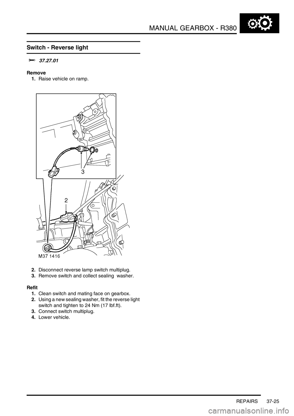
Switch - Reverse light
$% 37.27.01
Remove
1.Raise vehicle on ramp.
2.Disconnect reverse lamp switch multiplug.
3.Remove switch and collect sealing washer.
Refit
1.Clean switch and mating face on gearbox.
2.Using a new sealing washer, fit the reverse light
switch and tighten to 24 Nm (17 lbf.ft).
3.Connect switch multiplug.
4.Lower vehicle.
Page 510 of 1529
MANUAL GEARBOX - R380
OVERHAUL 37-39
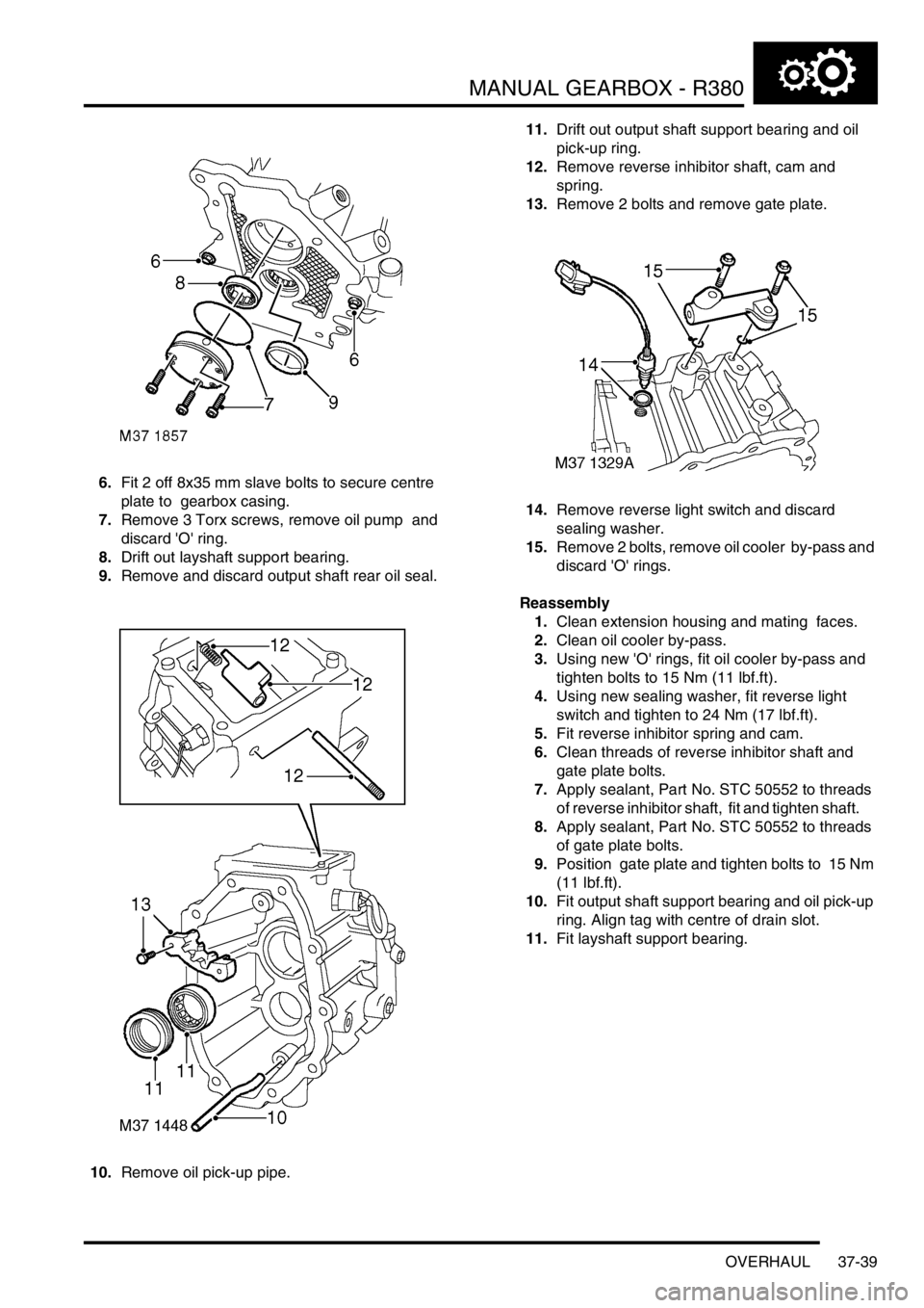
6.Fit 2 off 8x35 mm slave bolts to secure centre
plate to gearbox casing.
7.Remove 3 Torx screws, remove oil pump and
discard 'O' ring.
8.Drift out layshaft support bearing.
9.Remove and discard output shaft rear oil seal.
10.Remove oil pick-up pipe. 11.Drift out output shaft support bearing and oil
pick-up ring.
12.Remove reverse inhibitor shaft, cam and
spring.
13.Remove 2 bolts and remove gate plate.
14.Remove reverse light switch and discard
sealing washer.
15.Remove 2 bolts, remove oil cooler by-pass and
discard 'O' rings.
Reassembly
1.Clean extension housing and mating faces.
2.Clean oil cooler by-pass.
3.Using new 'O' rings, fit oil cooler by-pass and
tighten bolts to 15 Nm (11 lbf.ft).
4.Using new sealing washer, fit reverse light
switch and tighten to 24 Nm (17 lbf.ft).
5.Fit reverse inhibitor spring and cam.
6.Clean threads of reverse inhibitor shaft and
gate plate bolts.
7.Apply sealant, Part No. STC 50552 to threads
of reverse inhibitor shaft, fit and tighten shaft.
8.Apply sealant, Part No. STC 50552 to threads
of gate plate bolts.
9.Position gate plate and tighten bolts to 15 Nm
(11 lbf.ft).
10.Fit output shaft support bearing and oil pick-up
ring. Align tag with centre of drain slot.
11.Fit layshaft support bearing.
Page 511 of 1529
MANUAL GEARBOX - R380
37-40 OVERHAUL
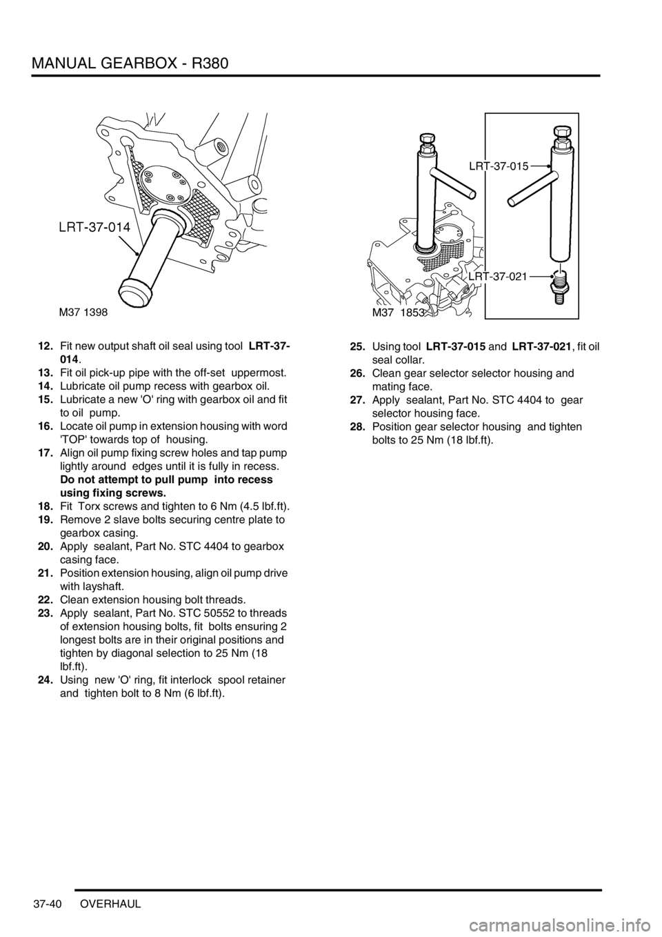
12.Fit new output shaft oil seal using tool LRT-37-
014.
13.Fit oil pick-up pipe with the off-set uppermost.
14.Lubricate oil pump recess with gearbox oil.
15.Lubricate a new 'O' ring with gearbox oil and fit
to oil pump.
16.Locate oil pump in extension housing with word
'TOP' towards top of housing.
17.Align oil pump fixing screw holes and tap pump
lightly around edges until it is fully in recess.
Do not attempt to pull pump into recess
using fixing screws.
18.Fit Torx screws and tighten to 6 Nm (4.5 lbf.ft).
19.Remove 2 slave bolts securing centre plate to
gearbox casing.
20.Apply sealant, Part No. STC 4404 to gearbox
casing face.
21.Position extension housing, align oil pump drive
with layshaft.
22.Clean extension housing bolt threads.
23.Apply sealant, Part No. STC 50552 to threads
of extension housing bolts, fit bolts ensuring 2
longest bolts are in their original positions and
tighten by diagonal selection to 25 Nm (18
lbf.ft).
24.Using new 'O' ring, fit interlock spool retainer
and tighten bolt to 8 Nm (6 lbf.ft). 25.Using tool LRT-37-015 and LRT-37-021, fit oil
seal collar.
26.Clean gear selector selector housing and
mating face.
27.Apply sealant, Part No. STC 4404 to gear
selector housing face.
28.Position gear selector housing and tighten
bolts to 25 Nm (18 lbf.ft).
Page 512 of 1529
MANUAL GEARBOX - R380
OVERHAUL 37-41
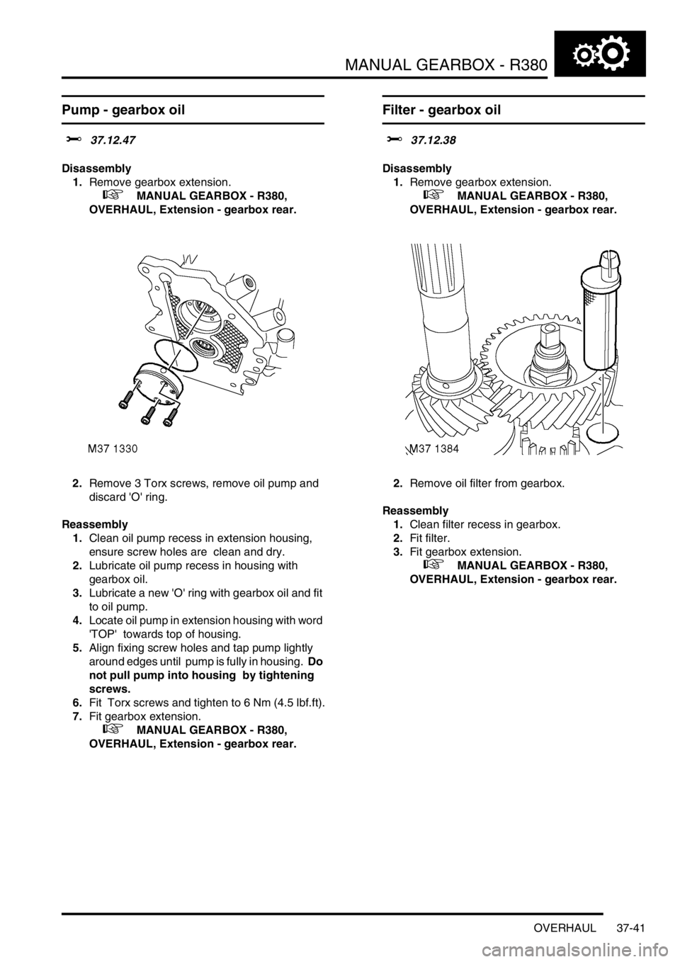
Pump - gearbox oil
$% 37.12.47
Disassembly
1.Remove gearbox extension.
+ MANUAL GEARBOX - R380,
OVERHAUL, Extension - gearbox rear.
2.Remove 3 Torx screws, remove oil pump and
discard 'O' ring.
Reassembly
1.Clean oil pump recess in extension housing,
ensure screw holes are clean and dry.
2.Lubricate oil pump recess in housing with
gearbox oil.
3.Lubricate a new 'O' ring with gearbox oil and fit
to oil pump.
4.Locate oil pump in extension housing with word
'TOP' towards top of housing.
5.Align fixing screw holes and tap pump lightly
around edges until pump is fully in housing. Do
not pull pump into housing by tightening
screws.
6.Fit Torx screws and tighten to 6 Nm (4.5 lbf.ft).
7.Fit gearbox extension.
+ MANUAL GEARBOX - R380,
OVERHAUL, Extension - gearbox rear.
Filter - gearbox oil
$% 37.12.38
Disassembly
1.Remove gearbox extension.
+ MANUAL GEARBOX - R380,
OVERHAUL, Extension - gearbox rear.
2.Remove oil filter from gearbox.
Reassembly
1.Clean filter recess in gearbox.
2.Fit filter.
3.Fit gearbox extension.
+ MANUAL GEARBOX - R380,
OVERHAUL, Extension - gearbox rear.
Page 517 of 1529
MANUAL GEARBOX - R380
37-46 OVERHAUL
Bearing - layshaft rear support
$% 37.20.58
Disassembly
1.Remove extension housing.
+ MANUAL GEARBOX - R380,
OVERHAUL, Extension - gearbox rear.
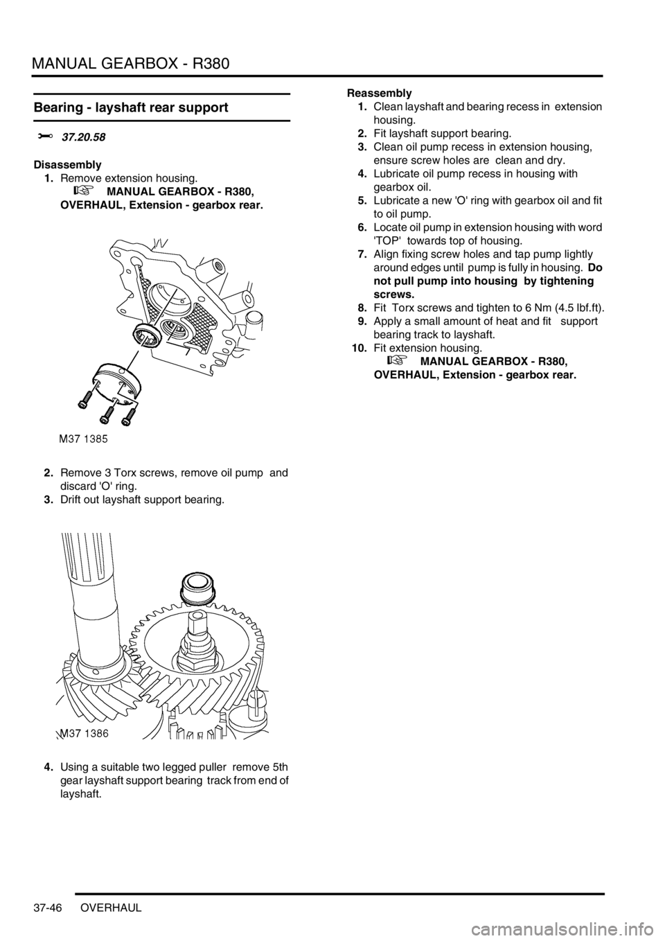
2.Remove 3 Torx screws, remove oil pump and
discard 'O' ring.
3.Drift out layshaft support bearing.
4.Using a suitable two legged puller remove 5th
gear layshaft support bearing track from end of
layshaft. Reassembly
1.Clean layshaft and bearing recess in extension
housing.
2.Fit layshaft support bearing.
3.Clean oil pump recess in extension housing,
ensure screw holes are clean and dry.
4.Lubricate oil pump recess in housing with
gearbox oil.
5.Lubricate a new 'O' ring with gearbox oil and fit
to oil pump.
6.Locate oil pump in extension housing with word
'TOP' towards top of housing.
7.Align fixing screw holes and tap pump lightly
around edges until pump is fully in housing. Do
not pull pump into housing by tightening
screws.
8.Fit Torx screws and tighten to 6 Nm (4.5 lbf.ft).
9.Apply a small amount of heat and fit support
bearing track to layshaft.
10.Fit extension housing.
+ MANUAL GEARBOX - R380,
OVERHAUL, Extension - gearbox rear.
Page 551 of 1529
TRANSFER BOX - LT230SE
41-26 REPAIRS
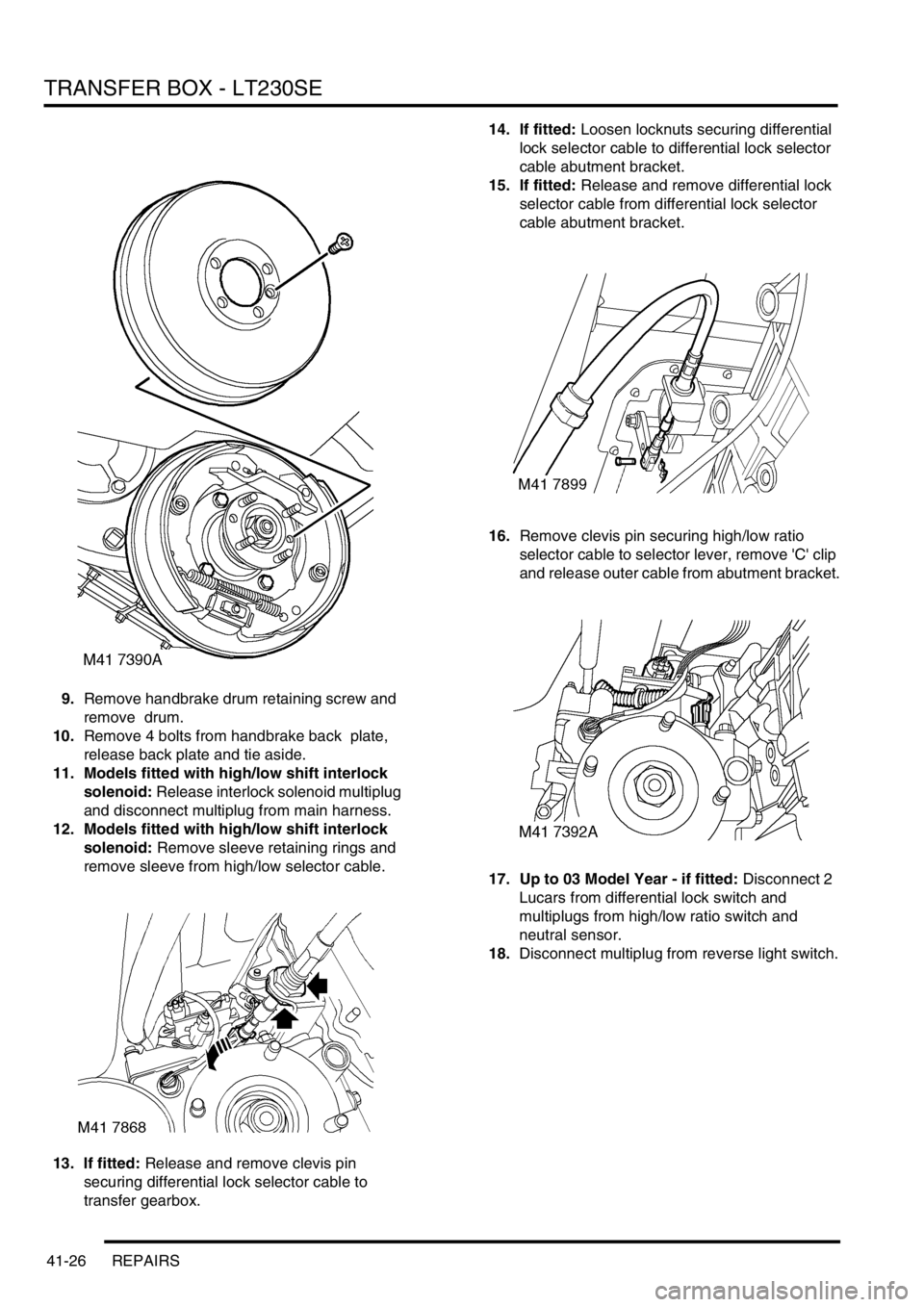
9.Remove handbrake drum retaining screw and
remove drum.
10.Remove 4 bolts from handbrake back plate,
release back plate and tie aside.
11. Models fitted with high/low shift interlock
solenoid: Release interlock solenoid multiplug
and disconnect multiplug from main harness.
12. Models fitted with high/low shift interlock
solenoid: Remove sleeve retaining rings and
remove sleeve from high/low selector cable.
13. If fitted: Release and remove clevis pin
securing differential lock selector cable to
transfer gearbox.14. If fitted: Loosen locknuts securing differential
lock selector cable to differential lock selector
cable abutment bracket.
15. If fitted: Release and remove differential lock
selector cable from differential lock selector
cable abutment bracket.
16.Remove clevis pin securing high/low ratio
selector cable to selector lever, remove 'C' clip
and release outer cable from abutment bracket.
17. Up to 03 Model Year - if fitted: Disconnect 2
Lucars from differential lock switch and
multiplugs from high/low ratio switch and
neutral sensor.
18.Disconnect multiplug from reverse light switch.