key LAND ROVER DISCOVERY 1999 Manual Online
[x] Cancel search | Manufacturer: LAND ROVER, Model Year: 1999, Model line: DISCOVERY, Model: LAND ROVER DISCOVERY 1999Pages: 1529, PDF Size: 34.8 MB
Page 1471 of 1529

NAVIGATION SYSTEM
87-18 DESCRIPTION AND OPERATION
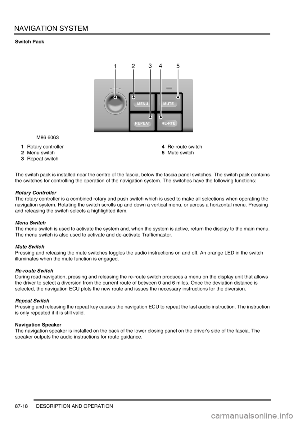
Switch Pack
1Rotary controller
2Menu switch
3Repeat switch4Re-route switch
5Mute switch
The switch pack is installed near the centre of the fascia, below the fascia panel switches. The switch pack contains
the switches for controlling the operation of the navigation system. The switches have the following functions:
Rotary Controller
The rotary controller is a combined rotary and push switch which is used to make all selections when operating the
navigation system. Rotating the switch scrolls up and down a vertical menu, or across a horizontal menu. Pressing
and releasing the switch selects a highlighted item.
Menu Switch
The menu switch is used to activate the system and, when the system is active, return the display to the main menu.
The menu switch is also used to activate and de-activate Trafficmaster.
Mute Switch
Pressing and releasing the mute switches toggles the audio instructions on and off. An orange LED in the switch
illuminates when the mute function is engaged.
Re-route Switch
During road navigation, pressing and releasing the re-route switch produces a menu on the display unit that allows
the driver to select a diversion from the current route of between 0 and 6 miles. Once the deviation distance is
selected, the navigation ECU plots the new route and issues the necessary instructions for the diversion.
Repeat Switch
Pressing and releasing the repeat key causes the navigation ECU to repeat the last audio instruction. The instruction
is only repeated if it is still valid.
Navigation Speaker
The navigation speaker is installed on the back of the lower closing panel on the driver's side of the fascia. The
speaker outputs the audio instructions for route guidance.
M86 6063
1
MUTE
RE-RTE
REPEAT
MENU
2345
Page 1475 of 1529

NAVIGATION SYSTEM
87-22 DESCRIPTION AND OPERATION
On-Board Monitor (Display Unit)
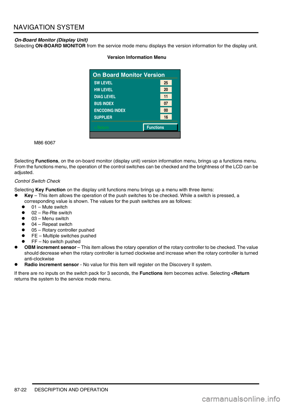
Selecting ON-BOARD MONITOR from the service mode menu displays the version information for the display unit.
Version Information Menu
Selecting Functions, on the on-board monitor (display unit) version information menu, brings up a functions menu.
From the functions menu, the operation of the control switches can be checked and the brightness of the LCD can be
adjusted.
Control Switch Check
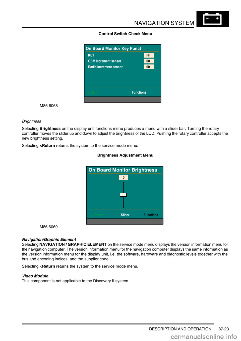
Selecting Key Function on the display unit functions menu brings up a menu with three items:
lKey – This item allows the operation of the push switches to be checked. While a switch is pressed, a
corresponding value is shown. The values for the push switches are as follows:
l01 – Mute switch
l02 – Re-Rte switch
l03 – Menu switch
l04 – Repeat switch
l05 – Rotary controller pushed
lFE – Multiple switches pushed
lFF – No switch pushed
lOBM increment sensor – This item allows the rotary operation of the rotary controller to be checked. The value
should decrease when the rotary controller is turned clockwise and increase when the rotary controller is turned
anti-clockwise
lRadio increment sensor - No value for this item will register on the Discovery II system.
If there are no inputs on the switch pack for 3 seconds, the Functions item becomes active. Selecting
M86 6067
On Board Monitor Version
SW LEVEL
HW LEVEL
DIAG LEVEL
BUS INDEX
ENCODING INDEX
SUPPLIER
< Return25
20
11
07
00
16
Functions
Page 1476 of 1529

NAVIGATION SYSTEM
DESCRIPTION AND OPERATION 87-23
Control Switch Check Menu
Brightness
Selecting Brightness on the display unit functions menu produces a menu with a slider bar. Turning the rotary
controller moves the slider up and down to adjust the brightness of the LCD. Pushing the rotary controller accepts the
new brightness setting.
Selecting
Navigation/Graphic Element
Selecting NAVIGATION / GRAPHIC ELEMENT on the service mode menu displays the version information menu for
the navigation computer. The version information menu for the navigation computer displays the same information as
the version information menu for the display unit, i.e. the software, hardware and diagnostic levels together with the
bus and encoding indices, and the supplier code.
Selecting
This component is not applicable to the Discovery II system.
M86 6068
On Board Monitor Key Funct
KEY
OBM increment sensor
Radio Increment sensor
< ReturnFF
00
00
Functions
M86 6069
On Board Monitor Brightness
< Return SliderFunctions
0
Page 1483 of 1529

NAVIGATION SYSTEM
87-30 REPAIRS
Display unit
$% 86.53.20
Remove
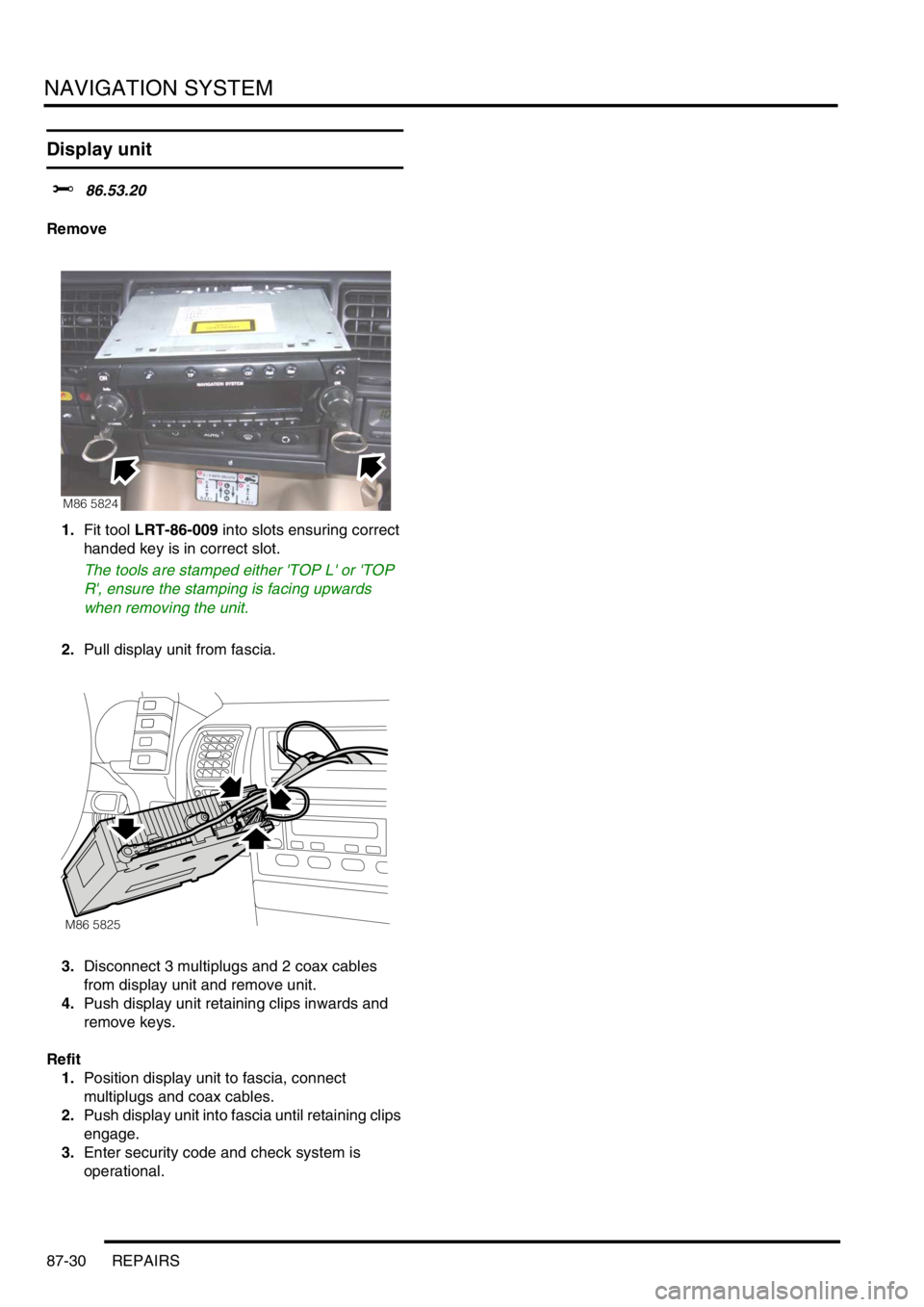
1.Fit tool LRT-86-009 into slots ensuring correct
handed key is in correct slot.
The tools are stamped either 'TOP L' or 'TOP
R', ensure the stamping is facing upwards
when removing the unit.
2.Pull display unit from fascia.
3.Disconnect 3 multiplugs and 2 coax cables
from display unit and remove unit.
4.Push display unit retaining clips inwards and
remove keys.
Refit
1.Position display unit to fascia, connect
multiplugs and coax cables.
2.Push display unit into fascia until retaining clips
engage.
3.Enter security code and check system is
operational.
M86 5824
M86 5825
Page 1523 of 1529

INSTRUMENTS
88-40 DESCRIPTION AND OPERATION
Audible warning speaker
The audible warning speaker is integral with the instrument pack and provides an audible warning to alert the driver
of the following situations:
lSeat belt warning lamp.
lKey in/lights on warning.
lSLABS command received warning.
lTransfer box in neutral warning.
lLights on warning.
It has a maximum pressure level of 87 dB at 1 metre (3.3 ft). The audible warning speaker is located on the rear of
the instrument pack.
The power input for the audible warning speaker is supplied by the instrument pack via fuse 27.
The BCU provides the earth paths for the following:
lThe seatbelt warning.
lKey in/lights on warning.
lLights on warning.
The SLABS ECU provides the earth paths for the SLABS commands. The EAT ECU provides the earth path for the
transfer box in neutral warning.
The BCU activates the audible warning speaker to produce audible warnings.
The audible warning speaker can operate with the ignition off.
The seatbelt warning will commence at key on, and in the event of a serial link failure, will terminate after 6 seconds.
The SLABS warnings are sounded only once for each received command.
The lights on warning and transfer box in neutral are sounded continuously until a sound off command is received.
Sound request number Sound functions Priority (1 = lowest, 6 = highest)
0Off 1
1 Seat belt warning 6
2Key-in warning 3
3 SLABS/ HDC warning 4
4 Transfer box in neutral warning 5
5 Lights on warning 2